Home page / Documents / Map of settings for triggering safety automatics Map of settings for triggering safety automatics is a document that is drawn up after commissioning. The work can be carried out by maintenance personnel or with the involvement of a third-party service contractor. Describes the action of automation when specific controlled values and indicators are achieved.
The map of settings for triggering safety automatics is a working internal document and addresses issues of gas supply, gas contamination of the premises, power supply, and the occurrence of emergency situations (fire). The card is not mandatory for domestic boilers.
Sample map of safety automatic activation settings
A completed sample and a visual example of a map of safety automatic activation settings. Contains completed data and quantitative indicators for a specific boiler.
Map of safety automatic activation settings (sample)
ORDER drawing up a map of safety automatic activation settings
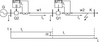
Selectivity map example
The selectivity map displays:
- currents of electrical protective devices;
- maximum and minimum values of short circuit currents at various points of the electrical circuit.
- protection response time
Based on these currents, some protection settings are selected and agreed upon.
The selectivity map of relay protection settings at substations powered by the power system is developed by the power system relay protection service. In accordance with the established procedure, it is agreed upon with the dispatch service, and is transferred to the substation to the duty personnel, the power supply dispatcher, and one copy is stored in the relay protection service of the enterprise. If it is necessary to change some settings or characteristics of circuit breakers or relays, a re-calculation is carried out, a selectivity map is drawn and its approval is carried out in the prescribed manner.
What does the security automation card contain?
The map indicates the specific type of boiler and the exact address of its location. The dimension and limit values of specific indicators and the actions of automation when they are achieved are indicated. Taken into account:
- gas supply;
- gas alarm;
- electricity supply;
- fire alarm.
The quantities considered are:
- maximum pressure in front of the burner;
- minimum pressure in front of the burner;
- minimum air pressure in front of the burner;
- extinguishing the torch in the boiler;
- CH4 content;
- CO content;
- increase in supply voltage U max;
- occurrence of a fire.
Time-current characteristics of the machine
The time-current characteristic can be of several types:
- dependent on current value;
- -independent time characteristic.
The time-current characteristics have an operation zone, characterized by the error of the protections, the accuracy of setting their settings and various external factors. The selectivity map usually shows 2 lines indicating this zone.
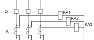
To construct selectivity maps in time-current axes, protection characteristics are constructed that have any type of current protection (current relays, relays, fuses, circuit breakers, etc.). Protective electrical devices are located sequentially in one plane; time-current characteristics for 2-3 devices are usually displayed on one map.
To correctly construct a selectivity map, all settings must be reduced to the same voltage , as a rule, this is 6 (10) kV.
The horizontal axis (abscissa) shows the current value, and the vertical axis (ordinate) shows time (s).
Selectivity maps are usually drawn for those protections that should be adjusted from each other in current and voltage, and which are located at the most remote point of the power network. Protection settings are considered selective if their time-current characteristics do not overlap or intersect.
5.9. RULES FOR TECHNICAL OPERATION OF POWER PLANTS AND NETWORKS OF THE RUSSIAN FEDERATION
5.9. Relay protection and electrical automation
5.9.1. Power electrical equipment of power plants, substations and electrical networks must be protected from short circuits and violations of normal conditions by relay protection devices, circuit breakers or fuses and equipped with electrical automation devices, including emergency automatic devices and automatic control devices.
Relay protection and electrical automatics (RPA) devices, including emergency automatics, must comply with the operating principles, settings, settings and output effects of power systems and be constantly in operation, except for devices that must be taken out of operation in accordance with their intended purpose. and the principle of operation, operating mode of the power system and selectivity conditions.
5.9.2. During operation, the conditions for normal operation of relay protection equipment and secondary circuits must be ensured (permissible temperature, humidity, vibration, deviations of operating parameters from nominal, electromagnetic compatibility conditions, etc.).
5.9.3. All cases of activation and failure of operation of relay protection and automation devices, as well as defects detected during their operation, must be carefully analyzed and taken into account in the prescribed manner by relay protection and automation services. Identified defects must be eliminated.
The higher organization in whose control or jurisdiction the device is located must be informed about each case of incorrect operation or failure to operate relay protection and automation devices, as well as about detected defects in circuits and equipment.
5.9.4. On relay protection and automation panels and double-sided service cabinets, as well as on panels and control panels on the front and back sides there must be inscriptions indicating their purpose in accordance with the dispatch names.
Equipment installed on panels, consoles and in cabinets with rotating panels must have inscriptions or markings on both sides according to the diagrams. The location of the inscriptions or markings must clearly identify the relevant device.
On panels with equipment belonging to different connections or different relay protection and automation devices of the same connection, which can be checked separately, clear demarcation lines must be marked and it must be possible to install a fence when checking individual relay protection devices.
Labels on devices operated by operating personnel must clearly indicate the purpose of these devices.
5.9.5. Power electrical equipment and power lines can only be energized with switched on relay protection against all types of damage. When certain types of protection are taken out of service or malfunction, the relay protection devices remaining in operation must provide complete protection of electrical equipment and power lines from all types of damage. If this condition is not met, temporary fast protection must be implemented or backup protection acceleration must be introduced, or the connection must be disconnected.
5.9.6. If there are high-speed relay protections and backup devices in the event of circuit breaker failure (CBF), all operations for switching on lines, buses and equipment after repair or being without voltage, as well as switching operations with disconnectors and air circuit breakers must be carried out with these protections put into operation; if during operations any of these protections cannot be put into operation or must be taken out of operation according to the principle of operation, acceleration should be introduced on backup protections or temporary protection should be performed, at least non-selective, but with the same duration of action as and constant protection.
5.9.7. The insulation resistance of electrically connected secondary circuits with voltages above 60 V relative to ground, as well as between circuits for various purposes that are not electrically connected (measuring circuits, operational current circuits, alarms), must be maintained within each connection at least 1 MOhm.
The insulation resistance of secondary circuits designed for an operating voltage of 60 V and below, powered from a separate source or through an isolation transformer, must be maintained at least 0.5 MOhm.
Insulation resistance is measured with a megohmmeter in the first case for a voltage of 1000 - 2500 V; and in the second case - 500 V.
Measurement of insulation resistance of circuits of 24 V and below of relay protection and automation devices on a microelectronic and microprocessor basis is carried out in accordance with the manufacturer’s instructions.
When checking the insulation of secondary circuits, the measures provided for in the relevant instructions must be taken to prevent damage to these devices.
5.9.8. When turned on after installation and the first preventive control, insulation relative to ground of electrically connected circuits of relay protection and automation and all other secondary circuits of each connection, as well as between electrically unconnected circuits located within the same panel, with the exception of circuits of elements designed for an operating voltage of 60 V and below , shall be tested at 1000 VAC for 1 min.
In addition, a voltage of 1000 V for 1 min. The insulation between the conductors of the control cable of those circuits where there is an increased probability of a short circuit between the conductors with serious consequences (gas protection circuits, capacitor circuits used as a source of operational current, secondary circuits of current transformers with a rated current value of 1 A, etc.) must be tested. ).
In subsequent operation, the insulation of relay protection and automation circuits (except for circuits with a voltage of 60 V and below) must be tested during preventive restorations with a voltage of 1000 V AC for 1 minute. or rectified voltage 2500 V using a megohmmeter or a special installation.
Testing the insulation of relay protection and automation circuits with voltages of 60 V and below is carried out during its measurement according to clause 5.9.7 of these Rules.
5.9.9. Newly installed relay protection devices and secondary circuits must be subjected to adjustment and acceptance tests before being put into operation.
Permission to introduce new devices and put them into operation is issued in the prescribed manner with an entry in the relay protection and electrical automation log.
5.9.10. The relay protection and automation service of the electrical engineering laboratory (ETL) of the power enterprise must have the following technical documentation for relay protection and automation devices in operation:
passport protocols;
instructions or guidelines for adjustment and testing;
technical data about devices in the form of settings and characteristics maps;
executive working diagrams: basic, installation or basic installation;
work programs for testing (putting into operation) complex relay protection and automation devices, indicating the sequence, method and location of disconnecting their circuits from the remaining operating relay protection and automation devices, equipment control circuits and current and voltage circuits; the list of groups of devices for which work programs must be drawn up is approved by the technical manager of the power system or power facility.
The results of maintenance must be recorded in the passport protocol (detailed records on complex relay protection and automation devices, if necessary, must be made in the work log).
Relay protection and automation services of all levels of management must have technical data about the devices managed and maintained by these services in the form of maps (tables) or logs (characteristics), schematic or block diagrams (technological operating algorithms).
5.9.11. Decommissioning, changing settings or changing the operation of relay protection devices must be formalized in accordance with paragraphs. 6.4.2; 6.4.5; 6.4.6 and 6.4.10 of these Rules.
If there is a threat of incorrect operation, the relay protection device must be taken out of operation taking into account the requirements of clause 5.9.5 of these Rules without the permission of superior operational dispatch personnel, but with subsequent notification to him (in accordance with local instructions) and subsequent filing of an application in accordance with clause. 6.4.6 of these Rules.
5.9.12. Relays, devices and auxiliary devices of relay protection and automation, with the exception of those whose settings are changed by operating personnel, are allowed to be opened only by employees of relay protection and automation services, ETL of electrical shops of power plants operating these devices, or in exceptional cases on their instructions to the operating personnel.
Work on relay protection devices must be performed by personnel trained and authorized to independently check the relevant devices.
5.9.13. On assemblies (rows) of terminals of control panels, cabinets and panels there should not be in close proximity terminals, the accidental connection of which can cause the connection to be turned on or off, a short circuit in the operating current circuits or in the excitation circuits of the generator (synchronous compensator).
5.9.14. When working on panels, consoles, in cabinets and in control and relay protection circuits, measures must be taken to prevent erroneous shutdown of equipment. Work must be performed only with insulated tools.
Carrying out these works without executive circuits, a test protocol and a standard or special work program for the output (input) of the relay protection device is not allowed.
Operations in the secondary circuits of current and voltage transformers (including test units) must be carried out with the removal of relay protection devices (or their individual stages), which, due to the principle of operation and settings (settings), can operate falsely during the execution of these operations.
At the end of the work, the serviceability and correct connection of the current, voltage and operational circuits must be checked. The operational circuits of relay protection and control circuits must be checked, as a rule, by testing in action.
5.9.15. Work on relay protection and automation devices that may cause incorrect disconnection of the protected or other connections, as well as other unintended effects on equipment, operating relay protection and protection devices, must be carried out according to an authorized application that takes into account these possibilities.
5.9.16. Monitoring the correct position of switching devices on relay protection and automation panels and cabinets, test block covers; monitoring the serviceability of fuses or circuit breakers in control and protection circuits; monitoring the operation of relay protection and automation devices according to the readings of external alarm devices and instruments available on the devices and panels (cabinets); testing of switches and other devices; exchange of high-frequency protection signals; measurements of controlled parameters of high-frequency tele-shutdown devices, low-frequency equipment of automation channels, high-frequency equipment of emergency automatics; measurement of unbalance current in busbar protection and bushing insulation monitoring devices; measurement of unbalance voltage in an open delta voltage transformer; testing of automatic restart devices, automatic reserve switching and fixing devices; clock factory for automatic oscilloscopes, etc. must be carried out by operating personnel.
The frequency of monitoring and testing, the list of devices and devices to be tested, the procedure for testing, as well as the procedure for personnel to act when detecting deviations from the standards must be established by local instructions.
5.9.17. Personnel of the relay protection and automation services of organizations operating electrical networks and ETL of power plants must periodically inspect all panels and control panels, relay protection panels, electrical automation, alarms, paying special attention to the correct position of switching devices (switches, control keys, linings, etc.) and covers test blocks and compliance of their positions with circuits and operating modes of electrical equipment.
The frequency of inspections must be established by the management of the power facility. Regardless of periodic inspections by the personnel of the relay protection and automation service, operational dispatch personnel must be responsible for the correct position of those relay protection and automation elements with which they are allowed to perform operations.
5.9.18. Relay protection devices and secondary circuits must be checked and tested to the extent and within the time limits specified in the current rules and instructions.
After incorrect operation or failure of operation of these devices, additional (post-accident) checks must be carried out.
5.9.19. Wires and cores of control cables connected to assemblies (rows) of clamps must be marked according to the diagrams. Control cables must be marked at the ends, in places of branching and intersection of cable flows, when passing through walls, ceilings, etc. The ends of the free conductors of control cables must be insulated.
5.9.20. When repairing damage to control cables with a metal sheath or extending them, the connection of cores must be carried out with the installation of sealed couplings or using boxes designed for this purpose. The specified couplings and boxes must be registered.
Cables with PVC and rubber sheaths must be connected, as a rule, using epoxy couplings or on adapter rows of clamps.
For every 50 m of one cable, on average there should be no more than one of the above connections.
5.9.21. When using control cables with core insulation that is susceptible to destruction under the influence of air, light and oil, the sections of cores from the clamps to the end cuts must have an additional coating to prevent this destruction.
5.9.22. The secondary windings of current transformers must always be shorted or shorted to relays and devices. The secondary circuits of current and voltage transformers and the secondary windings of filters connecting RF channels must be grounded.
5.9.23. Recording instruments installed at power plants and substations with automatic acceleration of recording in emergency modes, automatic oscilloscopes, including their triggering devices, recording instruments (ammeters, voltmeters and ohmmeters) and other devices used to analyze the operation of the relay protection device and determine the location of damage on the lines power transmission must always be ready for action. Commissioning and decommissioning of the specified devices must be carried out upon request.
5.9.24. In operational current circuits, selectivity of the action of protection devices (fuses and circuit breakers) must be ensured.
Circuit breakers and fuse blocks must be marked indicating their purpose and current.
5.9.25. In order for operating personnel to perform switching on panels and in cabinets of relay protection and automation devices using keys, pads, test blocks and other devices, tables of the position of the specified switching devices for the modes used or other visual control methods, as well as programs for complex switchings, must be used.
These switching operations must be recorded in the operational log.
5.9.26. On control panels of power plants and substations, as well as on panels and cabinets, switching devices in relay protection and automation circuits must be clearly located, and similar operations with them must be performed in the same way.
We bring the settings to one voltage.
We calculated the protection of a 10/0.4 kV transformer, so we bring all settings to 10 kV. The RTV-II and BMRZ-152-KL settings are obviously already adjusted to 10 kV.
Let us bring the settings of the 0.4 kV machine given to us to the design voltage. To do this you need to use the formula:
Is.r.10kv = Is.r.0.4kv × Unom.nn/Unom.in = Is.r.0.4kv / 25
, where Iс.р.10 is the protection setting, normalized to the 10 kV side (desired)
Is.r. 0.4 — protection setting on the 0.4 kV side (initial data)
Please note that the settings for the 0.4 kV circuit breaker are given in relative values, exactly as they are set on the Micrologic 5.0 front panel (see catalog). Here are the settings:
In10kv = 2500/25 = 100A
Ir10kv = 0.8×100 = 80 A
Isd10kv = 2.5x80 = 200 A
Here we give an example of converting settings from a voltage of 0.4 to a voltage of 10 kV, however, when using the Greedis-KS program this is not necessary!
Gridis-KS can bring the settings to the design voltage “independently”. Read more about this.