- home
- Relay protection
- Calculation of relay protection of a 10 kV line
A power transmission line transports electricity from point A to point B. At a voltage of 6-35 kV, power lines are made with a compensated or isolated neutral.
This circumstance imposes certain features of the implementation of relay protection devices. For example, in these networks, long-term (up to several hours) operation with a single-phase ground fault (SGF) is acceptable. In this case, the load is transferred to another line, after which a shutdown occurs. There are also options when protection from ground faults only affects the signal, or is absent altogether.
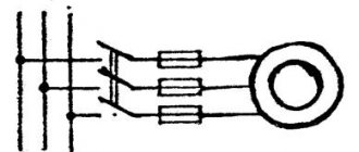
Protection against two-phase and three-phase short circuits is ensured by installing relay protection and automation kits in two phases out of three: phase A and phase C. Since a single-phase short circuit is not critical, in case of a two-phase or three-phase short circuit the entire line will always be disconnected.
- f.A+B
=> switches off via f.A line - f.A+C
=> switches off in two phases - f.B+C
=> f.C line will be disconnected
It's another matter if a double ground fault occurs. This is when two parallel lines are closed in one opposite phase. As a result, we have a total of 6 short circuit options:
- in 2 cases one line is disconnected
- in 2 cases another line
- and in 2 more cases 2 lines are disconnected at once
It turns out that in 4 out of 6 options one of the lines remains in operation. This is an advantage of this connection method. It’s another matter if, when the phases are separated, they suddenly put A and B, or B and C in the wrong place. Then the options will become worse and the likelihood of accidents will increase.
A modest example, we measured the current on a section, or on some kind of engine, through the terminal block in the relay compartment. And after starting up and increasing the load, we discovered that what we were displaying was real nonsense. As a result, it turned out that phase B and zero from the CT were swapped. As they say, a defect has been identified that needs to be fixed. This is why there is adjustment, so that after installation, you can check the readiness and put it into operation for trouble-free operation.
Tricky question? Why is a double short circuit to the same phase not considered a double ground fault?
Now let's move on to the consideration and quick calculation of the following protections: MTZ, TO, OZZ. Runaway, since there are so many nuances that people have written dozens of books on this topic. Protection can be performed either separately on a relay or in a complex, as part of a microprocessor terminal. To protect the line, three-stage current protection can be used, where:
- 1st stage (instantaneous current cut-off) 3I>>>
- 2nd stage (with time delay) 3I>>
- 3rd stage (MTZ) 3I>
The TO has the highest current setting - this is rough protection, while the MTZ is more flexible and allows you to perform long-range backup functions.
MTZ lines 6-35 kV
I have already considered MTZ, but repetition is the mother of learning. Time-delay overcurrent protection acts as the first stage of three-stage line protection. To make the calculation, it is necessary to calculate the protection operation current, setting current, time delay and differentiate from neighboring protections.
1) At the first stage, we determine the protection operation current, taking into account self-starting currents and other overcurrents that flow during the elimination of a short circuit on the previous element:
in this formula we have the following components:
Is.z.
— current of protection 2РЗ, the value that we determine
kn
— reliability factor, which in fact can be considered rather as a detuning factor for increasing the set value; for microprocessor ones it is 1.05-1.1, for electromechanical ones it is 1.1-1.4.
kszp
— self-starting coefficient, its meaning is that during a short circuit the voltage drops and the motors self-start. If there are no 6(10) kV motors, then the coefficient is assumed to be 1.1-1.3. If there is a load, then the calculation is made under the condition of self-start of the electric motor from a completely inhibited state. The self-starting coefficient is defined as the ratio of the calculated self-starting current to the maximum operating current. That is, knowing the self-starting current, you may not know the maximum operating current, although without this knowledge it will not be possible to calculate the self-starting current - in general, it will not be possible to shorten the formula much.
kv
— return coefficient of maximum current relays; for digital - 0.96, for mechanics - 0.65-0.9 (depending on the type of relay)
Iwork.max.
— the maximum operating current, taking into account possible overloads, can be obtained from dispatchers, if you have a telephone number and authority. For transformers up to 630 kVA = 1.6-1.8*Inom, for transformers of two-transformer substations 110kV = 1.4-1.6*Inom.
2) At the second stage, we determine the protection operation current, coordinating the protections L1 and L2:
Is.s.s.s.
— tripping current of protection 2РЗ
kn.s.
— coordination reliability coefficient, the value of this coefficient is from 1.1 to 1.4. For relay RT-40 - 1.1, for RTV - 1.3...1.4.
kр
— current distribution coefficient, with one power source, is equal to unity. If there are several sources, then it is calculated through equivalent circuits and element resistances.
First sum in brackets
- this is the largest of the geometric sums of the overcurrent protection currents of parallel operating previous elements.
The second sum
is the geometric sum of the maximum values of the operating currents of the previous elements, except for those with which coordination occurs.
3) At the third stage, we select the largest of the currents determined by conditions 1) and 2) and calculate the current setting:
kсх
- circuit coefficient, this coefficient shows how many times the current in the relay is greater than the current I2 of the current transformer in symmetrical normal operation; when switched on to phase currents (star or open star) it is equal to 1, when switched on to the phase current difference (triangle) it is 1.73.
nt
— transformation ratio of the current transformer.
4) Next, the sensitivity coefficient is determined, which must be greater than or equal to the value specified in the PUE.
The ratio of the minimum current flowing in the relay, under the least favorable operating conditions, to the relay operating current (set). For MTZ, the value of kch must be at least 1.5 for a short-circuit in the main protection zone and at least 1.2 for a short-circuit in distant redundancy zones.
5) Determine the time setting
The meaning of the time settings is as follows: if we have a short circuit as in the figure above, then switch L1 (located closer to the short circuit) must first turn off; this is necessary in order to leave undamaged sections of the system in operation.
That is, tс.2рз=tс.1рз+dt
, where delta t is the selectivity level. This value depends on the speed of the protection (in particular, the accuracy of the time relay) and the on-off time of the switches.
If the previous RP is a current cut-off or the RP is made using electronic (semiconductor) relays, dt can be taken as 0.3 s. If electromechanical relays are used in the relay protection, then dt can be 0.5...1.0. For different relays this value can reach several seconds.
As was written above, a feature of MTZ is the accumulation of time delays from element to element. And the larger the dt value, the larger the remote setpoint will be. To solve this problem, digital relays (dt=0.15...0.2s) and identical switches should be installed. After all, if the switches are of the same type, then the response time is the same for all. And if it is small, then the total value will be small.
In general, the choice of MTZ consists of three stages:
- failure of 2RZ during overcurrents in post-emergency modes
- coordination of 2РЗ with 1РЗ
- ensuring sensitivity during short circuit at the end of L1 (working zone) and at the end of L2 (long-range backup zone)
MTZ with independent time delay
Overcurrent protection is the main protection for overhead lines with one-way power supply. MTZ is equipped not only with power lines, but also with power transformers, cable lines, and powerful motors with voltages of 6 and 10 kV.
Rice. 4.2.1
Location of protection at the beginning of each line on the power supply side. In Fig. 4.2.1 shows the action of the protections at point K. The time delays of the protections are selected according to a stepwise principle and do not depend on the amount of current flowing through the relay.
Calculation of line current cutoff
Maintenance can be performed both with a time delay (current cut-off with slowdown) and without it. When calculating the TO, it is adjusted from the maximum short circuit current at the end of the protected line. The transformer's maintenance is also adjusted against the inrush of the magnetizing current. Formulas and more details about current cutoff are written here.
To prevent the effects of overcurrents and short circuits that cannot be switched off with a time delay, non-selective maintenance without a time delay
. This is applicable to protect synchronous machines from short circuits on the buses, which can lead to disruption of the stability of parallel operation of the TG with the power system and disruption of the power supply. Formula for determining the response current of non-selective maintenance:
In the above formula:
Uс.min
— phase-to-phase voltage of the system in minimum operating mode (0.9...0.95), V
kn
— already familiar reliability factor = 1.1…1.2
zs.min
— system resistance to the location where the cutoff is installed, Ohm
ko
— coefficient of dependence of the residual voltage at the location of the cutoff installation on the distance of the 3ph short circuit, determined by the dependence of the graphic
Residual voltage is the voltage at which the dynamic stability of synchronous generators (Ures>0.6) and electric motors (Ures>0.5) is ensured.
This non-selective maintenance is used in conjunction with automation (AVR, Automatic Automatic Recloser), which ensures fast response when disconnecting dangerous short circuits. However, for collaboration it is necessary to perform a number of activities:
- rebuild the maintenance from the magnetizing currents of transformers,
- repair fault repair on the LV busbars of transformers located in its coverage area
- coordinate maintenance with fuses, switches and other devices located within its coverage area
Single-phase earth fault protection
When calculating protection against short circuit protection, you should know the method of grounding the neutral and, depending on this, carry out further actions. In 6-35 kV networks, zero-sequence current protection is used. The conditions for its selection are to determine the protection operation current and determine the sensitivity coefficient
In this formula
Ic.feed.max
— feeder’s own capacitive current
kn
— reliability coefficient equal to 1.2
kbr
— coefficient of capacitive current inrush when a short-circuit fault occurs
Iс.sum
- the total capacitive current of the network, which can be determined using the formulas below:
for isolated neutral:
Operation in a network with an isolated neutral is allowed if the capacitive current does not exceed:
- 30A for 6kV network
- 20A for 10kV network
If the value of the capacitive current exceeds the obtained value, then it is necessary to compensate it using a reactor, that is, switch to another type of neutral grounding.
Current data can also be obtained from specialized organizations. Or determine experimentally what gives the most accurate and realistic value.
Relay protection: sensitivity and its coefficient
In domestic practice, the term “sensitivity” is usually used to denote a property of relay protection that makes it possible to identify calculated types of damage and abnormal modes of the power system in the coverage area of the relay protection.
In the PUE [1], the concept denoted by the term “sensitivity” [2] is used to characterize any protection, regardless of the voltage of the electrical installation, but there is no definition of the concept denoted by this term in this document.
If the sensitivity of some products can be determined directly [1], then in relay protection this characteristic is assessed indirectly, and the assessment method depends on the voltage of the electrical installation [1].
It should be noted here that in many other countries sensitivity assessment is not carried out [3].
According to the PUE, to assess the sensitivity of protection in electrical installations with voltages over 1000 V, a sensitivity coefficient is used [4, 5, 6].
The value of the sensitivity coefficient for protections that respond to an increase in the controlled value is found as the ratio of their calculated values within the protected zone to the response setting.
For line current protection, the sensitivity coefficient is generally found using the formula:
(1)
where is the minimum short circuit current for the protected line (usually at the end of the protected section); — protection operation current.
It is generally accepted that in the general case such protection will work correctly if the following relation is satisfied:
The value of the sensitivity coefficient found using this formula (1) must be no less than the normalized value established in [1], and which, depending on the type of protection, can vary from 1.5 to 2.0.
In [3] it is shown that when the value of the sensitivity coefficient changes from 1.2 to 1.4, the probability of protection operation changes slightly, from 0.998 to 1.000.
Let us now consider how it is recommended to determine the sensitivity coefficient of the current cutoff in one of the methods for calculating settings (see [4], example 2.1).
To save space, the initial data for the calculation are given in the explanations to the formulas.
The calculation begins with determining the starting current of the electric motor I start ed according to the formula:
I start ed = k start I nom = 5.7 113.2 = 645 A (2)
where k start is the catalog value of the starting current equal to 5.7 for an asynchronous electric motor of the A4 series;
I nom – rated current of the electric motor, determined from known values of rated power, rated voltage, efficiency and power, or taken from catalog data.
The starting current can also be determined from the rated current of the electric motor given in the catalog data.
The smallest value of the two-phase short circuit current at the motor terminals is found using the formula:
(3)
where – = 3500 is the value of the three-phase short circuit current at the power inputs of the asynchronous electric motor in the minimum operating mode of the system (given in the initial data for calculation).
The current cut-off current is calculated using the formula:
(4)
We find the protection sensitivity coefficient for a two-phase short circuit using formula (1), substituting the found values into it:
(5)
Based on the calculations carried out in the method [4], the conclusion was made: “the sensitivity coefficient of the TO turned out to be less than two.”
Can we say that a decrease in the sensitivity coefficient by only 7% (2.00-1.86=0.14; 0.14/2.00=0.07) compared to the value specified in the PUE makes this protection unsuitable? ?
Note that if in formula (5) the calculated value = 3031 A is used, instead of the rounded value (3000), the calculated value of the sensitivity coefficient will be only 6% (3031/1612 = 1.88) less than the value recommended by the PUE.
The approximate nature of this approach is also visible in the fact that in formula (4) the condition for the failure of the maintenance device when starting the electric motor is the choice of a multiplier equal to 2.5, which leads to an increase in the calculated current and, ultimately, a decrease in the sensitivity coefficient.
If we assume and then experimentally prove that the current cut-off will not operate when choosing a setting equal to 2.35 of the starting current of the electric motor, then the value of the sensitivity coefficient even at a starting current of 645 A will satisfy the requirements of the PUE.
In the method under consideration, instead of reducing the factor in formula (4), an action that is similar in essence is proposed - reducing the second factor by “refining” the starting current of the electric motor [2].
Note that in any case, the real starting current of the electric motor will remain unknown, and all conclusions will be based on calculations made using the catalog data of the electric motor.
The method proposes to use the well-known formula (6) to find the starting current of the electric motor using the resistance of the supply system found by calculation = 0.92 Ohm and the starting resistance of the electric motor = 5.37 Ohm:
(6)
The operating current of the current cut-off at this value of the starting current will be:
(7)
In this case, the value of the sensitivity coefficient increases to:
(8)
If we put the calculated value of current A into the original formula (5), then the value of the sensitivity coefficient will increase even more and become equal to 2.18.
After obtaining the desired result, the method [4] concluded: “The sensitivity coefficient of the TO turned out to be more than two, so there is no need to use differential protection.”
The reader can draw his own conclusion about this conclusion.
In electrical installations with voltages up to 1000 V, to assess the sensitivity of current protections, instead of the “sensitivity coefficient”, the PUE provides another characteristic - the short circuit current multiplicity, specified as a percentage in relation to:
— rated current of the fuse link;
— current setting of the circuit breaker with the maximum instantaneous release;
— rated current of the release with an unregulated inverse current characteristic;
— tripping current of the release with an adjustable characteristic inversely dependent on the current.
The current multiplicity values according to [1], depending on the type of protection device, can be in the range:
By dividing the right and left sides of the inequality by 100%, you can see that, in essence, this is a slightly modified way of specifying the sensitivity coefficient.
The above allows us to draw the following conclusions:
1.
The use of the term “relay protection sensitivity” is primarily a tribute to tradition, and the concept denoted by this term does not have a standardized definition.
2.
Assessing the sensitivity of relay protection differently, depending on the voltage of the electrical installation, creates a false impression of the difference in concepts denoted by different terms:
— “short circuit current ratio” (used in electrical installations with voltages up to 1000 V);
— “sensitivity coefficient” (used in electrical installations with voltages over 1000 V).
The standardization of the “sensitivity coefficient,” and even more so the verification of this coefficient when calculating protection settings, is largely due to the properties of previously used protection relays and was transferred to digital devices without sufficient technical justification.
Literature:
1.
Rules for electrical installations. M.: Glavgosenergonadzor of Russia, 1998, 608 p.
2.
Sensitivity // [Electronic resource “All about relay protection”], Access mode (The material was originally posted here).
3.
Shalin A.I. Reliability and diagnostics of relay protection of power systems. Novosibirsk, NSTU publishing house, 2002, 384 p.
4.
Gondurov S. A., S. V. Mikhalev, M. G. Pirogov, A. L. Solovyov. Relay protection of electric motors with voltage of 6-10 kV using BMRZ terminals. Calculation method. St. Petersburg, PEIPK, 2013, 60 p.
5.
Chernobrovov N.V., Semenov V.A. Relay protection of energy systems. M.: Energoatomizdat, 1998, 800 m.
6.
Sensitivity coefficient // [Electronic resource “All about relay protection”], Access mode.
7.
What is the protection sensitivity coefficient?//[Electronic resource], Access mode.
[1]
For example, in sensitivity metrology, measuring instruments are found as the ratio of the change in the output signal to the change in the measured quantity.
[2]
To obtain the required sensitivity coefficient, the starting current should not exceed 600 A
.