The response parameters of any relay protection device must meet the requirements set out by the PUE [1] (see chapters 3.2, 5.3).
To correctly select the response settings, the operating manuals for digital relay protection devices produced by the Mekhanotronika Research and Development Center traditionally provided methods for calculating them only for the most complex protection algorithms.
Due to a significant increase in the number of produced digital devices and the putting forward of new requirements by organizations that certify digital devices for use at the facilities of JSC FGC UES, methods for calculating settings for all protection algorithms provided for in digital devices produced by the Scientific and Technical Center were introduced into the operational documentation. Mechanotronics".
For this purpose, the company has developed guidelines for calculating settings that fully take into account:
- requirements and recommendations set out in the PUE;
- features of the protection algorithms used in digital blocks of the BMRZ and BMRZ-100 series.
The development of methodological guidelines was carried out by specialists from the Scientific and Technical Center "Mekhanotronics" with the participation of Ph.D. Solovyov A.L., head of the department of relay protection and automation of power plants, networks and systems of the St. Petersburg Energy Institute for Advanced Studies.
This publication opens a series of articles that provide methods for calculating settings, illustrated with practical examples.
Guaranteed disconnection
A circuit breaker is suitable for guaranteed disconnection of a circuit if it satisfies all the requirements for a disconnector (at its rated voltage) in the relevant standard (see Functions of low voltage equipment: isolating (breaking)). In this case, it is called a circuit breaker-disconnector and is marked on its front surface in the form of a symbol
This category includes all low-voltage switching devices from Schneider Electric: Multi 9, Compact NS and Masterpact.
Rated current of the circuit breaker when using releases with different setting ranges
A circuit breaker, which may be equipped with releases having different current setting ranges, is assigned a rated value corresponding to the rated value of the release with the highest tripping current setting level.
Example:
The NS630N circuit breaker can be equipped with four electronic trip units with rated currents from 150 to 630 A. In this case, the rated current of this circuit breaker will be 630 A.
Rated current (In)
This is the maximum value of current that a circuit breaker equipped with a special overcurrent trip relay can carry indefinitely at the ambient temperature specified by the manufacturer, without exceeding the specified maximum temperature of live parts.
Example
Circuit-breaker with a rated current In = 125 A at an ambient temperature of 40 °C, equipped with an overcurrent tripping relay suitably calibrated (set to 125 A). The same circuit breaker can be used at higher ambient temperatures, but at the expense of underrating. For example, at an ambient temperature of 50 °C, this switch will be able to carry 117 A indefinitely, but at 60 °C, only 109 A, provided that the specified temperature requirements are met.
The rated current of the circuit breaker is reduced by reducing the setting of its thermal relay. The use of an electronic release that can operate at high temperatures makes it possible to operate circuit breakers (with reduced current settings) at an ambient temperature of 60 °C or even 70 °C.
Note:
In circuit breakers conforming to IEC 60947-2, the current In is usually equal to Iu for the entire switchgear, where Iu is the rated continuous current.
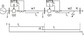
A short article about the functions of maximum current protection, the choice of the minimum and maximum value of the operating current of the MTZ device. The magnitude of the electric current is perhaps the most important parameter of the operation of an electrical installation or electric drive. Exceeding the maximum permissible current value can lead to destruction of conductors and equipment failure. The reason for the increase in current can be not only a short circuit, but also an overload in the circuit. In any case, any electrical circuit needs protection from the occurrence of unacceptable currents in it, which in electrical engineering is commonly called overcurrent protection (MCP). Overcurrent protection of circuits and equipment is implemented using such elements as circuit breakers , fuses, fuse links and, of course, overcurrent relays. Choosing the rating of a device or MTZ apparatus is an extremely responsible matter. An error in this choice will lead to the fact that the protection will be characterized by frequent false positives, or will simply be ineffective, which is of course unacceptable. Therefore, leaving aside the Russian “maybe”, you should extremely accurately calculate the required rated current of the MTZ apparatus. The minimum value of the “set point” - the protection operation current - can be determined based on the power of consumers connected to the circuit for long periods of time. For single-phase consumers (for example, for a line of household electrical outlets), it will be enough to divide the total power in watts by the network voltage - 220 volts. The power factor in the apartment can be neglected, assuming the load is purely active. For three-phase consumers, you can calculate the current in each phase using the phase voltage and power of the electrical receivers connected to this phase. If the MTZ is installed for an electric motor, then the amount of electric current received will need to be divided by the power factor, approximately equal to 0.7. Thus, it is enough to select a device with a rating slightly higher than the calculated current value, and we will obtain short circuit protection. At the same time, of course, we must not forget that the vast majority of MTZ devices have the ability to adjust the setting within certain limits around the nominal value. And, despite the fact that when carrying out electrical installation work they are most often limited only to the choice of the overcurrent setting for the maximum load, protection against overload currents cannot be neglected. It is very important to match the characteristics of the circuit breaker to the type of consumer. So, for a “socket” wiring network, as a rule, a 25-amp “C” type “automatic” is selected. For lighting networks, a 16 or 10 amp circuit breaker is usually installed. This option has been tested in practice and is certainly suitable for protecting the electrical wiring of most residential or office premises. However, for incoming circuit breakers and switches with fuse-links, it is better to determine the upper limit of the overcurrent setting. The short circuit current in the circuit is determined indirectly: when the power supply is turned off, the phase conductor at the end of the cable line is connected to the working neutral conductor. Then the total resistance of the resulting phase-zero loop is measured. The phase voltage is divided by the measured resistance. The result obtained will be the value of the short circuit current. At the same time, for accurate measurements, it is of course better to use not a multimeter, but a special certified device that determines active resistance with high accuracy.
Characteristic Z
Also has a spread when operating on direct and alternating voltage and is designed to provide maximum protection for electronic control devices. The work curve is shown below:
When operating on alternating voltage, shutdown occurs when 2–3 ratings are reached, when operating at constant voltage, 2–5.
As you can see, choosing a circuit breaker to protect electrical circuits is not such a simple task as it seems at first glance. Therefore, when choosing a circuit breaker, it is necessary to compare not only the nominal data (voltage, current, phase), but also to know the operating characteristics of the system for which the circuit breaker is selected, so that the circuit breaker you choose fully provides protection for your equipment.
Disturbing influences on the process
External and internal causes that cause a deviation of the controlled process parameter from the specified setpoint value are called “disturbing influences” or simply “disturbance”.
Even in a simple system there are a number of points at which disturbance can occur. For example, a leak in a pipeline could cause a disturbance along the supply line. This would reduce the amount of water supplied to the reservoir, causing changes in process conditions. Other input disturbances could arise due to an increase in pressure in the pipeline or an unexpected drop in temperature (frost).
Disturbances can also occur from the target output side. One type of such disturbance could be an increase or decrease in the task for the target product. Stopping for repairs or maintenance of one part of the process requires changing the target output of another part of the system.
A third source of process disturbances could be the process equipment itself. For example, a disturbance may be caused by a pump failure in the supply line or in the recovery line.
Overcurrent relay trip setting (Irth or Ir)
With the exception of small circuit breakers, which are easily replaced, industrial circuit breakers are equipped with replaceable ones, i.e. replaceable overcurrent trip relays. In order to adapt the circuit breaker to the requirements of the circuit it controls and avoid the need to install larger cables, trip relays are usually adjustable. The breaking current setting Ir or Irth (both commonly used) is the current above which a given circuit breaker will trip the circuit. It is also the maximum current that can pass through the circuit breaker without tripping the circuit. This value must necessarily be greater than the maximum load current Ib, but less than the maximum permissible current in a given circuit Iz (see Practical values for a protection circuit).
Thermal relays are usually regulated in the range of 0.7-1.0 In, but in the case of electronic devices this range is larger and is usually 0.4-1.0 In.
Example
(
Fig. H30
): An NS630N circuit breaker fitted with a 400 A STR23SE trip unit which is adjusted to 0.9 In will have a tripping current setting of: Ir = 400 x 0.9 = 360 A.
Note:
for circuits equipped with unregulated releases, Ir = In. Example: for a 20 A C60N circuit breaker, Ir = In = 20 A.
Rice.
H30: Example of NS630N circuit breaker with STR23SE trip unit adjusted to 0.9In (Ir = 360 A)
Time-current characteristics of machines
The operation of automatic circuit breakers occurs due to the action of its main elements - thermal and electromagnetic releases. The design of the thermal release consists of a bimetallic plate that heats up under the influence of flowing current. As a result, it bends and activates the release mechanism. For operation, a long-term load is required, inversely proportional to the time delay. The level of overload directly affects the heating of the plate and the response time of the thermal release.
The main components of an electromagnetic release are a coil and a core. When the current reaches a certain level, the magnetic field of the coil draws in the core, under the influence of which the release mechanism is activated. The device responds instantly in case of short circuits, without waiting for the thermal release to heat up. The operation time of the machine depends on the strength of the current passing through the circuit breaker. This dependence is precisely the time-current characteristic of the protective device.
The Latin symbols B, C and D are marked on the body of each device. Each of them corresponds to the multiple of the setting of the electromagnetic release to the rated value of the machine. That is, with the help of these letters the instantaneous tripping current of the release or the sensitivity of the circuit breaker is displayed. This parameter indicates the minimum current at which the protective device is switched off instantly. Thus, the time-current characteristic of each specific machine is denoted in Latin letters. The symbol “B” corresponds to the characteristics 3-5 x ln, “C” – 5-10 x ln and “D” – 10-20 x ln.
The meaning of these figures must be considered using the example of two machines of equal power, that is, with the same rated current, for example, models B16 and C16. For switch B16, the operating range of the electromagnetic release will be 16 x (3-5) = 48-80 A. Accordingly, for the C16 circuit breaker this range will be within 16 x (5-10) = 80-160 amperes. Thus, in the presence of a current of 100 A, the B16 model will instantly turn off, and the C16 device will turn off only a few seconds after heating the bimetallic plate.
For residential and administrative buildings, the most suitable options are considered to be automatic machines marked B and C. This is due to the absence of large starting currents and the extremely rare switching on of high-power electric motors. Category D machines are used mainly in those facilities where there are powerful electric motors and other devices with high starting currents.
The time-current characteristic curve necessarily takes into account the temperature of the protective device itself. In the case of the first trip, it takes longer to turn off because the bimetallic strip is cold. When triggered again, when the plate has already been previously heated, the shutdown occurs faster.
Short circuit tripping current setting (Im)
Instantaneous releases or those triggered with a short time delay are designed to quickly turn off the circuit breaker in the event of large short-circuit currents. Their response threshold Im:
- for household circuit breakers it is regulated by standards, for example IEC 60898;
- for industrial circuit breakers, it is specified by the manufacturer in accordance with current standards, in particular IEC 60947-2.
A wide range of trip units are available for industrial circuit breakers, allowing the user to tailor the circuit breaker's protective functions to the specific load requirements (see Figure H31
,
H32
and
H33
).
— low setting: 2 — 5 In — standard setting: 5 — 10 In
1.5 Ir ≤ Im ≤ 10 Ir Instantaneous operation (I), time not adjustable: I = 12 - 15 In
[2] 50 In in the IEC 60898 standard, which according to most European manufacturers is an unrealistically high value (MG = 10-14 In). [3] For industrial use, values are not regulated by IEC standards. The values shown above are those that are commonly used.
Rice.
H31: Trip current ranges for overload and short circuit protection devices for low voltage circuit breakers
Fig.
H32: Trip curve of thermomagnetic combination circuit breaker
Ir: overload tripping current setting (thermal or long-time relay) Im: short-circuit tripping current setting (magnetic or short-time relay) Ii: release setting instantaneous short-circuit breaking current Icu: breaking capacity
Rice.
H33: Circuit breaker electronic trip curve