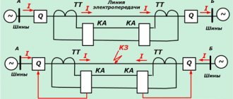
When there is a short circuit, the current in the line increases. This feature is used to perform current protection. Overcurrent protection (MCP) comes into action when the current in the line phases increases above a certain value.
Current protections are divided into overcurrent protection, in which a time delay is used to ensure selectivity, and current cutoffs, where selectivity is achieved by selecting the operating current. Thus, the main difference between different types of current protection is in the method of ensuring selectivity.
Rice. 4.1.1
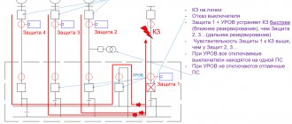
Differences from current cut-off
Logical bus protection
The MTZ uses time relays that make it possible to ignore voltage surges, which is impossible with cutoff (which is triggered not only during a short circuit episode, but also when the current increases of any other nature and duration). In addition, the use of the shut-off mechanism requires operator intervention to restore normal system operation. The relays themselves return to their original state when the cause of the opening is eliminated.
Overcurrent protection with voltage triggering
In some cases, it is not possible to provide sufficiently sensitive current-only protection, especially at substations supplying motor loads. To increase sensitivity, voltage blocking protection can be used.
A functional diagram of an MTZ with an additional voltage element is shown in Fig. 5.11. The voltage measuring element is carried out using a KV
and acts together with the relay
KA
of the current measuring element according to the logical “AND” circuit to start the time relay
CT.
Rice. 5.11. Functional diagram of MTZ with voltage starting.
During a short circuit, when the current increases and the voltage decreases, both measuring elements (both current and voltage) are triggered and, with a given time delay, the overcurrent protection acts on the shutdown electromagnet YAT
through the indicator relay
KN
and the block contact of the switch
SQ
.
If, as a result of an overload of the protected element, the current relay KA
is activated, the voltage actuator blocks the action of the overcurrent protection, since the voltage relay
KV
does not operate. The inactivity of the voltage relay during overload is ensured by selecting a setting such that it does not operate at the minimum operating voltage.
The voltage measuring element can be made with three relays connected to phase-to-phase voltages (Fig. 5.12.a). This scheme ensures reliable operation of the voltage element in case of any type of phase-to-phase short circuit, since at least one of the phase-to-phase voltages is reduced.
| A) | b) |
Rice. 5.12. Trigger voltage circuit diagrams.
In the second option (Fig. 5.12.b), the measuring element is made of a combination of two voltage relays KV 1, KV 2.
The maximum voltage relay
KV 2
, connected through a negative sequence voltage filter
ZV 2
, is used to start overcurrent protection during asymmetrical short circuits.
The minimum voltage relay KV 1,
connected via a break contact
KV 2
, is designed to operate during three-phase short circuits. This circuit of the voltage measuring element, compared to the first option (Fig. 5.12.a), provides higher sensitivity for both asymmetrical and symmetrical short circuits.
The primary tripping current of the overcurrent protection with voltage starting is determined by the condition of detuning from the rated current I nom
transformer:
.
The minimum voltage relay activation setting is selected based on the following conditions:
return after disconnecting the external short circuit
detuning from residual self-starting voltage after action of automatic reclosure or automatic transfer system
, where: – phase-to-phase voltage at the installation site of the overcurrent protection device under self-starting conditions after disconnecting the external short circuit, can be taken equal to ; – the phase-to-phase voltage at the installation site of the overcurrent protection system under self-starting conditions after the action of automatic reclosure or automatic reclosure of braked electric motors can be taken equal to ; – detuning coefficient equal to 1.2; – return coefficient equal to 1.1.
Negative sequence voltage of relay KV 2
the combined voltage actuator (Fig. 5.12.b) is adjusted from the unbalance voltage
of the filter ZV 2
:.
The sensitivity for a current relay is determined by the above formula; for minimum voltage relay according to the formula:
, where: is the primary value of the phase-to-phase voltage at the installation site of the overcurrent protection device with a metallic three-phase short circuit between phases at the design point in the mode that determines the maximum value of this voltage.
To protect a two-winding transformer, it is sufficient to install two-element current protection on both sides. At the same time, to protect the transformer with the connection diagram Y/∆
, the relays on the HV side must be connected to three CTs assembled in a delta circuit. LV side cut-off can be used as logic bus protection. Maximum protection is used as maximum input protection, and an additional current element blocks the logical differential protection of the HV side transformer.
Date added: 2019-07-15; ; We will help you write your work!
Source
Operating principle
MTZ is a type of power network protection mechanism using a relay, used when there is a threat of a short circuit on a certain section of the electrical circuit.
The operating principle of overcurrent protection is quite similar to that of the cut-off mechanism. If, when using the latter, the current is cut off immediately, then when using MTZ, the shutdown occurs after a certain period of time. It's called time delay. The value it takes is determined by the proximity of the incident to the food provider. The further away the segment is, the lower the number. The value by which the indicator of the nearby section differs from that of the remote section (selectivity level) describes the period after which the protection is activated in the near section (disabling the far section as well), if it was not activated in the distant section where the short circuit incident occurred.
Important! The step indicator must be kept small so that the system has time to turn on before the incident causes serious damage to the electrical network.
Types of overcurrent protection
In electrical networks, 4 types of overcurrent protection are used. Their use is dictated by the conditions that need to be created for reliable operation of electrical equipment.
MTZ with current-independent time delay
In such devices, the time delay does not change. To set the settings for a period sufficient to activate relays with independent characteristics, selectivity stages are taken into account. Each subsequent shutter speed (towards the current source) increases from the previous one by a period of time corresponding to the selectivity stage. That is, during calculations it is necessary to comply with selectivity conditions.
Overcurrent protection with current-dependent time delay
In this protection, the process of setting the overcurrent protection settings requires more complex calculations. Dependent characteristics, in cases with induction relays, are selected according to the IEC standard: tсз = A / (kn - 1), where A, n are sensitivity coefficients , k = Iwork / Iaver - current multiplicity.
It follows from the formula that the time delay is no longer a constant. It depends on several parameters, including the strength of the current entering the relay windings, and this dependence is inverse. However, the shutter speed is not linear; its characteristic approaches hyperbole (Fig. 3). Such MTZ are used to protect against dangerous overloads.
MTZ with limited current-dependent time delay
Devices of this type of relay protection combine two stages of protection: a dependent part with a hyperbolic characteristic and an independent one. It is noteworthy that the time-current characteristic of the independent part is direct, smoothly conjugate with the hyperbola. At small multiples of critical currents, the dependent period characteristic is steeper, and at large multiples, the curve is flat (used to protect high-power electric motors).
MTZ with start (blocking) from a minimum voltage relay
In this type of differential protection, a combination of overcurrent protection is used using the influence of minimum voltage. In an electromechanical relay, the contacts will open only when the increase in current in the network leads to a drop in the potential difference. If the drop exceeds the lower limit of the set voltage, this will trigger the protection. Since the setting is set for a voltage drop, the relay will not respond to sudden surges in current in the network.
Overcurrent protection circuits
Three-phase overcurrent protection circuit on direct operating current
The protection circuit is shown in Fig. 4.2.2: Main relays :
- The starting element is spacecraft current relays.
- Time organ - time relay CT.
Auxiliary relays:
- KL – intermediate relay;
- KH – indicator relay.
Rice.
4.2.2 An intermediate relay is installed in cases where the time relay cannot close the circuit of the YAT trip coil due to insufficient power of its contacts. The block contact of the SQ switch serves to interrupt the current flowing through the trip coil, since the contacts of the intermediate relays are not designed to open.
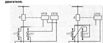
Two-phase overcurrent protection circuits on direct operating current
In cases where the MTZ must respond only to phase-to-phase short circuits, two-phase circuits with two or one relay are used, as they are cheaper.
Dual relay circuit
Rice. 4.2.3
Advantages
1. The circuit reacts to all phase-to-phase faults on the lines.
2. More economical than a three-phase circuit.
Flaws
Less sensitivity with 2-phase behind the transformer with winding connection Y/–11 deg. (Twice less than a three-phase circuit).
Rice. 4.2.4
If necessary, sensitivity can be increased by installing a third current relay in the common wire of the current circuits. The sensitivity doubles - the circuit becomes equivalent in sensitivity to a three-phase one.
The circuits are widely used in networks with an isolated neutral , where only phase-to-phase short circuits are possible.
two-phase circuits are used as protection from phase-to-phase and in networks with a solidly grounded neutral, while for protection from single-phase, additional protection is installed that responds to zero-sequence current.
Single-relay MTZ circuit
Rice. 4.2.5
The circuit responds to all cases of phase-to-phase short circuits.
Advantages
Only one current relay.
Flaws
- Less sensitivity compared to a 2-relay circuit between phases AB and BC.
- Protection failure in one of three possible cases of 2-phase behind the transformer with winding connection Y/–11 deg.
- Lower reliability - if a single current relay malfunctions, the protection fails. The circuit is used in 6...10 kV distribution networks and for protecting electric motors.
Rice. 4.2.6
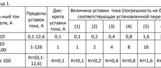
Calculation of current overcurrent protection
The stability of operation and reliability of operation of overcurrent protection depends on the settings of the operating current parameters. Calculations should ensure guaranteed operation of the relay in case of emergency, but its operation should not be affected by the parameters of the load current, as well as short-term surges that occur during engine starting mode.
It should be remembered that overly sensitive relays can cause false alarms. On the other hand, underestimated response parameters cannot guarantee the safe, stable operation of electrical appliances. Therefore, when calculating settings, it is necessary to choose a golden mean.
There is a formula for calculating the average current value to which an electromagnetic relay reacts [1]:
where I s.z. – the minimum primary current to which the protection must respond, and I n. max . – limit value of load current.
The relay return current is selected in such a way that it is sufficient to re-close the contacts in the used device. To determine it we use the formula:
Here I in – return current, k n . – reliability coefficient, k з – self-starting coefficient, I slave. max . – the value of the maximum operating current.
In order to bring the return and operation currents as close as possible, a return coefficient is introduced, calculated by the formula:
kв = I in / I s.z. taking into account which Iс.з. = kn.×kz.×Iwork. Max. /kv
Ideally, kв = 1, but in practice this coefficient is always less than one. The higher the value of kv, the higher the sensitivity of protection. Hence the conclusion: to increase sensitivity, it is necessary to select kv in a range tending to 1.
Setting the settings
Differential protection
Overcurrent protection is determined by how correctly the setting is selected - the current value, upon reaching which the function is activated. When determining its value, the purpose of the network is taken into account (for example, when an electric motor starts independently after a temporary power outage, the indicator may exceed the nominal value, then the MTZ should not turn it off) and the minimum fault current in it. With a dependent (fully or limited) time-current characteristic, they focus on the value when the overload relay is about to operate, and the time is set based on the independent part.
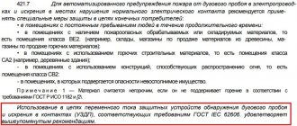
Important! Sometimes a blocking in a protective system is set with a voltage orientation, then the response parameter set as a setting becomes it.