METHODS OF VOLTAGE AND CURRENT MEASUREMENT
General information
Current and voltage measurements are carried out in direct and alternating current circuits of a wide range of frequencies and pulsed ones.
The highest measurement accuracy is obtained in DC circuits When measuring in AC circuits, the accuracy of measurements decreases with increasing frequency; here, in addition to estimating the root-mean-square, average-rectified, average and maximum values, sometimes it is necessary to observe the shape of the signal under study and know the instantaneous values of current and voltage.
Current and voltage meters, regardless of their purpose, when turned on, must not disrupt the operating of the circuit of the object being measured ; ensure a small measurement error, while eliminating the influence of external factors on the operation of the device, high measurement sensitivity at the optimal limit, quick readiness for operation and high reliability.
The choice of instruments that perform current and voltage measurements is determined by a combination of many factors, the most important of which are: the type of current being measured; approximate frequency range of the measured quantity and amplitude range; shape of the measured voltage (current) curve; power of the circuit in which the measurement is carried out; power consumption of the device; possible measurement error (requirements for specific devices will be indicated below).
If the required measurement accuracy, permissible power consumption and other requirements can be provided by ammeters and voltmeters of the electromechanical group, then this simple direct reading method should be preferred . In low-power DC and AC circuits, digital and analog electronic voltmeters If it is necessary to measure voltages with higher accuracy, you should use instruments whose operation is based on comparison methods, in particular the contrast method.
Current measurement is possible by direct assessment using analog and digital ammeters, as well as indirectly . In this case, the voltage is measured across a standard resistor with a known resistance. to study the shape and determine the instantaneous values of voltage and current .
Voltage measurement in DC circuits
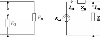
Direct assessment method. When using the direct assessment method, the voltmeter is connected in parallel to the section of the circuit where the voltage needs to be measured; When measuring the voltage across a load in a circuit with an energy source whose EMF and internal resistance ,
the voltmeter is connected in parallel to the load (Fig. 7.1).
If the internal resistance of the voltmeter is ,
then the following relative voltage measurement error will occur:
(7.1)
where is the actual voltage value across the load before turning on the voltmeter; —
measured value of voltage across the load
.
The ratio of resistances is inversely proportional to the ratio of the power consumption of the voltmeter to the power of the circuit ,
That's why
(7.2)
(both at and at).
To reduce the methodological error in voltage measurement, the power consumption of the voltmeter should be small and its internal resistance high.
|
Voltage measurement in direct current circuits can be performed with any voltage meter operating on direct current (magnetoelectric, electrodynamic, electromagnetic, electrostatic, analog and digital electronic voltmeters). The choice of a voltage meter is determined by the power of the measurement object and the required accuracy. The range of measured voltages ranges from microvolts to tens of kilovolts If the measurement object is powerful, electromechanical voltmeters electronic voltmeters
Comparison methods . Compensation method (opposition method)
measurement consists of balancing, carried out by switching on the balance indicator either two electrically unrelated but oppositely directed voltages or emf, or two separately controlled currents. The compensation method is used to directly compare voltages or emf, current and indirectly to measure other electrical as well as non-electrical quantities converted into electrical ones.
Figure 7.2 – Voltage compensation circuit
The following compensation schemes are used: a) voltage or EMF (Fig. 7.2); b) electric currents (Fig. 7.3).
The diagram shown in Fig. 7.2, the most common. In it, the measured voltage is compensated by an equal, but opposite in sign, known voltage .
The voltage drop is created by the current across a variable compensating reference resistance
.
The change occurs until it is equal to
.
The moment of compensation is determined by the absence of current in the circuit of the magnetoelectric galvanometer; in this case, no power is consumed from the measurement object.
Figure 7.3 – Current compensation circuit
The compensation method ensures high measurement accuracy.
Devices used to perform measurements using the compensation method are called potentiometers
or
compensators.
In practical compensator circuits, to ensure the required measurement accuracy, the current in the operating circuit is determined not by a direct assessment ammeter, but by a compensation method using a standard EMF of a normal element. Normal elements provide a time-constant EMF equal to 1.01865 V at a temperature of 20 °C, an internal resistance of 500-1000 Ohms, and an overload current of 1 μA. As the ambient temperature changes, the EMF value decreases for each degree of temperature increase:
(7.3)
Where —
EMF at temperature; — EMF at 20 sw:space=»720″/>»> ;.
The compensator circuit is shown in Fig. 75. It contains a source of auxiliary emf; to power the working circuit, which includes the adjusting ,
compensating and exemplary resistance.
A normal element whose EMF is connected
the NE terminals ,
desired EMF
is connected to the
X .
G
is used as an indicator of balance. When working with the compensator, two operations are performed:
1) set the current in the working circuit of the compensator using a source of auxiliary EMF (position 1
switch
B);
2) measure the desired EMF (position 2
switch
B).
Figure 7.4 – Compensator circuit
To set the operating current, the ambient temperature is first determined, then the exact value of the EMF of a normal element for a given temperature is calculated using (7.3). Next, set the exemplary resistance ,
the value of which is selected depending on the values of the current in the operating circuit and the EMF at temperature (the resistance consists of a coil with a constant resistance value and a temperature decade connected in series with it).
Then switch B
is placed in position
1
and the EMF of the normal element is opposed to the voltage drop on, which is regulated by changing the value of the current in the operating circuit with a resistor
.
the
zero deviation of the galvanometer
,
i.e. After establishing the operating current for measurement, switch B
put in position
2
and by adjusting the exemplary compensating resistance the current in the galvanometer circuit is again brought to zero
.
Then
(7.4)
where I
— current value set at position
1
of switch B
;
- the value of the exemplary compensating resistance at which the equilibrium state occurs.
Resistance is performed according to special circuits that provide constant resistance between points 3, 4
and variable resistance between points
3, D,
as well as the required number of signs and counting accuracy.
The specified conditions are met by circuits with replacement (Fig. 7.5) and shunt decades (Fig. 7.6). In a scheme with replacement decades, all sections of the upper decades are completely duplicated by the corresponding sections of the lower decades. The switches of two identical decades are mechanically connected. When moving the switches, the total resistance remains unchanged: if the resistance values of the upper decades decrease, then the resistance values of the lower decades increase, and vice versa. Compensating voltage can be removed from the upper or lower decades. Each subsequent decade has a section resistance ten times less than the previous one. In a circuit with shunting decades, at each position of the double switches, one section of the upper decade is shunted by nine sections of the lower decade, with a total resistance between the points 3
and
4
(see Fig. 7.4) remains unchanged. The current through the resistance sections of the lower decade is ten times less than the current through the resistance sections of the upper decade, i.e.
Figure 7.5 – Scheme with replacement decades
(7.5)
The compensation voltage can be defined as follows:
(7.6)
Where ,
— the number of included sections of the upper and lower decades, respectively;
,
- voltage drops in individual sections of the corresponding decades.
The considered resistance options ensure that its full value remains unchanged, and therefore the current remains unchanged at the time of compensation, if the EMF of the auxiliary source is .
Figure 7.6 – Scheme with shunt decades
Depending on the resistance value of the operating circuit, there are DC compensators of high resistance (high resistance 10-40 kOhm, operating circuit current , order of measured voltage 1-2.5 V, measurement error 0.02% of the measured value) and low resistance (low resistance 10 -1000 Ohm; operating circuit current, measured voltage order up to 100 mV, measurement error 0.6% of the measured value).
Circuit designs and designs of DC compensators may be different.
High-resistance compensators are used for testing magnetoelectric, electrodynamic voltmeters; to expand the limits of voltage measurement by compensators, high-resistance resistor voltage dividers with taps from certain parts are used, which makes it possible to reduce the measured voltage by a factor of (10, 100, 1000) to a value close to the upper measurement limit of the compensator . When using a voltage divider, some power is consumed from the measurement object, i.e. one of the main advantages of the compensation method is lost.
When measuring EMF sources with high internal resistance or voltages acting in high-resistance circuits, the input resistance of magnetoelectric and electronic voltmeters may not be large enough, so it is advisable to use a differential or compensation method.
Figure 7.7 – Circuit for measuring DC voltage using the differential method
Differential method
is based on measuring the difference between the measured and reference voltages with their incomplete compensation.
The measurement scheme is shown in Fig. 7.7. A high-resistance electronic voltmeter with a sensitive limit is used to measure the difference voltage between the measured and reference voltages. A magnetoelectric analog or digital voltmeter is used to measure reference voltage .
It is recommended to measure the approximate value with a voltmeter
,
and only then set the voltage convenient for reading using the voltmeter
.
The measured voltage at the specified polarity of turning on the voltmeter is defined as.
The differential method provides high accuracy of voltage measurement. The measurement error is determined mainly by the error of the voltmeter measuring .
Circuit input impedance
(7.7)
and is much higher than the input resistance of the voltmeter
Galvanometric compensators
are used to measure small DC voltages (of the order of V).
The main elements of a galvanometric compensator (Fig. 7.8) are: measuring mechanism magnetoelectric mirror galvanometer,
model
photoresistors
constant voltage sources
magnetoelectric
A beam of light from the projector Pr is directed onto the galvanometer mirror.
In the absence of voltage, a beam of light reflected from the mirror equally illuminates the photoresistors, resulting in a current.
When a voltage is applied to the input of the voltage meter, a current appears in the galvanometer circuit ,
the moving part of the galvanometer rotates through a certain angle and the illumination of the photoresistors is redistributed and their resistance changes.
According to the connection diagram of photoresistors and polarity, the resistance of the photoresistor will decrease and a will increase. Current will flow through the resistor ,
creating a compensating voltage
almost equal to the measured
voltage .
The value of the current automatically changes depending on the change in the measured voltage
,
but always in such a way that the condition is satisfied
,
ensured by small changes in the current in the galvanometer circuit:
(7.8)
The more sensitive the galvanometer, the smaller the changes will be the corresponding change in current needed to fulfill the condition .
Increased sensitivity is achieved through the use of a special design of the galvanometer, which provides a maximum angle of rotation of the moving part at currents of the order of magnitude.
The value of the compensating current depends on the values ,
relative change in photoresistance and can reach several tens of microamperes.
Figure 7.8 – Diagram of a galvanometric compensator
The galvanic compensator has high sensitivity with high input resistance.
Electrometric compensators
- voltage meters that use an electromechanical electrometer and have a very high input resistance ( ).
They are simple and easy to use. An electromechanical electrometer is a sensitive electrostatic measuring mechanism, the lightweight moving part of which is suspended by a thin elastic thread. The mechanism uses a light indicator of the position of the moving part. The diagram of the electrometric compensator is shown in Fig. 7.9, where the electric electrometer consists of two fixed plates 1, 2
and a movable plate
3,
located symmetrically relative to the fixed ones.
A miniature mirror is attached to the movable cover. An excitation voltage is supplied to the stationary plates ,
which makes it possible to increase sensitivity and the ability to set the readings to zero electrically (with the terminals closed using a variable resistor)
.
The operating principle of an electrometric compensator is similar to the operation of a galvanometric compensator.
When connecting the measured voltage, the moving part of the electrometer E
will rotate through a certain angle, which will lead to a redistribution of light fluxes illuminating the photoresistors and, to the appearance of a compensation current and, accordingly, a voltage
balancing
the measured voltage
.
The moving part of the electrometer will deflect until the voltages are equal
.
Since the resistance of the feedback resistor
RK
can be insignificant, the current can be relatively large and can be measured with a microammeter. The input current of the compensator is determined by the leakage currents, so it is small, and therefore the input resistance is high (Ohm). In addition to voltage meters, highly sensitive electrometric current meters are also being built.
Figure 7.9 – Diagram of an electrometric compensator
DC current measurement
Direct assessment method . The ammeter is connected in series to the open circuit of the circuit under study.
Series connection of an ammeter with internal resistance in a circuit with an EMF source and resistance (load and source resistance) leads to an increase in the total resistance and a decrease in the current flowing in the circuit.
Relative current measurement error
(7.9)
where is the actual value of the current in the circuit before the ammeter is turned on; — measured value of current in the circuit .
The resistance ratio can be replaced by the ratio of the power and consumption of the ammeter and the circuit itself, respectively:
(7.10)
smaller the ammeter power consumption compared to the circuit power consumption , the smaller the measurement error
in which the measurement is carried out.
Therefore, an ammeter connected in series to the measurement circuit must have low resistance, i.e.
The range of values of direct currents, the measurement of which is encountered in various fields of technology, is extremely large (from currents A to tens and hundreds of thousands of amperes). Therefore, naturally, the methods and means of measuring them are different .
Direct current measurements can be made with any direct current meter: magnetoelectric, electrodynamic, analog and digital electronic ammeters. If it is necessary to measure very small currents, significantly less than the total deviation current, with a magnetoelectric meter Current amplification can be achieved by switching on bipolar transistors using a common emitter (CE) , which provides a low input impedance to the amplifier.
Currents A can be measured directly using highly sensitive magnetoelectric mirror galvanometers and galvanometric compensators.
Indirect current measurement. In addition to direct measurement of currents with ammeters, it is possible to indirectly measure currents using standard resistors included in the open circuit and highly sensitive voltage meters. The measured current is determined by
where is the voltage drop across the reference resistor
,
measured by a voltmeter, DC compensator.
To obtain minimal measurement errors, the resistance of the resistor must be much less than the resistance of the circuit in which the current is measured.
Measurement of small currents. The maximum sensitivity of any current meter depends on the thermal noise current, which is smaller the higher the internal resistance of the meter. To reduce this current to level A in the frequency band from 0 to 0.01-0.1 Hz, it is necessary to use devices with an internal resistance of at least Ohm, therefore magnetoelectric galvanometers, galvanometric compensators, amplifiers based on bipolar transistors are classified as relatively low-resistance measuring devices and, therefore, they cannot be used when measuring currents less than A. To measure small direct and slowly varying currents, passive current-to-voltage converters are used in combination with a sensitive voltage meter that has a very high input impedance (up to ohms) and a low noise level. Parasitic currents should also be reduced as much as possible. Passive converters include resistive, capacitive, and logarithmic converters.
In resistive current-to-voltage converters
high-resistance resistors are used, the resistance value of which depends on the current flowing through the resistor and changes over time under the influence of temperature, humidity, etc. The nominal resistance values of manufactured high-resistance resistors up to Ohm significantly depend on the applied voltage, the temperature coefficient up to and time drift up to several percent in year.
In a narrow frequency band, a high-resistance resistor can be represented as a parallel connection of resistance and capacitance (on the order of tenths of a picofarad).
In capacitive current-to-voltage converters
rate of change of voltage) use capacitors with high-quality insulation or special air capacitors. The conversion error is determined by the measurement error of the capacitor capacitance and the change in capacitance during the accumulation of charge under the influence of slow polarization of the dielectric, therefore the capacitance of the capacitor depends on the frequency of the measured current. A capacitor is subject to the same current and voltage noise sources as a resistor. The shunt resistance of the capacitor reaches Ohms.
In logarithmic current-to-voltage converters
Electrovacuum and semiconductor devices with a current-voltage characteristic described by a logarithmic dependence are used. The resistance of the logarithmic element changes under the influence of the measured current in such a way that the absolute voltage increments at the same relative current increments remain unchanged. Depending on the type of logarithmic element and its operating mode, the voltage increment per decade of current ranges from 50 mV to several volts. The behavior of a logarithmic element as a small current-to-voltage converter can be most fully described by its current-voltage characteristic. The logarithmic element is shunted by insulation resistance and capacitance between the electrodes. The influence of the shunt resistance is manifested in the distortion of the current-voltage characteristic. The operating frequency band of the converter is determined by the capacitance of the logarithmic element.
Low current meters with resistive and capacitive current-to-voltage converters use electrometric amplifiers (EMA) to amplify the output voltage of the converter necessary for the operation of indicating or recording devices. An EMU input circuit can be characterized by an input impedance, an input capacitance, an equivalent interference voltage source, and an equivalent interference current source .
A significant increase in the input resistance of the EMU is obtained through the use of electrostatic measuring mechanisms, electrometric lamps (with grid current up to A), and dynamic capacitors (capacitive vibration converters of direct voltage to high frequency voltage) in the input stage; varicaps (semiconductor controlled capacitances); MOS transistors (insulated gate field effect transistors); ferrodielectrics .
Ferroelectrics —
a class of dielectrics that exhibit electrification in the absence of an external electric field.
If you indicate the polarization vectors with arrows, then you can schematically represent
No external margin
Voltmeter
A voltmeter is a device for measuring voltage at the poles of a current source or at some other part of the circuit.
Voltmeters are very similar in appearance to ammeters. How to distinguish them then? If the ammeter scale shows the letter $A$, then the voltmeter scale will definitely have the letter $V$.
Voltmeters come in different types. It depends on their purpose. You will most often see either demonstration voltmeter (Figure 1, a) or a laboratory one (Figure 1, b).
As you can guess from the names of the devices, a demonstration voltmeter is used to demonstrate experiments, and you will use a laboratory voltmeter when performing laboratory work.
Figure 1. Types of voltmeters
On the scale of each voltmeter there is a higher (maximum) voltage value that it is capable of measuring. Exceeding this limit may result in device failure.
Voltmeter in an electrical circuit
A voltmeter is connected to a certain section of the electrical circuit where the voltage needs to be measured.
Please note that if an ammeter connected in series to an electrical circuit will show the same current value in all sections of the circuit, then with a voltmeter we have a completely different story. It is designed to measure voltage on a specific section of the circuit.
To indicate electrical circuit diagrams, the voltmeter has its own symbol (Figure 2). It looks like a circle with the letter $V$ in the middle.
Figure 2. Symbol for indicating a voltmeter on an electrical circuit diagram