Transformer no-load concept
When a transformer has a dedicated power supply to one winding, while the others are in an open state. This process leads to energy leakage, which is called no-load losses. Its development occurs under the influence of a number of external and internal factors.
The power of the transformer is not fully used, and part of the energy is lost due to some magnetic processes, features of the primary winding and insulating layer. The latter option affects when using devices operating at a higher frequency.
Measuring efficiency
When calculating losses, the efficiency indicator is also determined. It shows the ratio of the active type power at the input and output. This indicator is calculated for a closed system using the following formula:
Efficiency = M1/M2, where M1 and M2 are the active power of the transformer, determined by measurements on the input and output circuits.
The output is calculated by multiplying the rated power of the installation by the power factor (cosine of the angle j squared). It is taken into account in the above formula.
In transformers 630 kVA, 1000 kVA and other powerful devices, the efficiency indicator can be 0.98 or even 0.99. It shows how efficiently the unit operates. The higher the efficiency, the more economically energy is consumed. In this case, energy costs during equipment operation will be minimal.
Having considered the methodology for calculating transformer power losses, short circuits and no-load, it is possible to determine the cost-effectiveness of the equipment, as well as its efficiency. The calculation method involves using a special calculator or performing calculations in a special computer program.
What factors influence losses
Modern transformers reach 99% efficiency under full load conditions. But devices continue to be improved, trying to reduce energy loss, which is almost equal to the sum of idle losses arising under the influence of various factors.
Insulation
If the tie rods have poor or insufficient insulation, a short-circuit will occur. This is one of the main factors for this transformer problem. Therefore, more attention should be paid to the insulation process, using high-quality specialized materials for these purposes.
Eddy currents
The development of eddy currents is associated with the flow of magnetic flux along the magnetic circuit. Their feature is perpendicular to the flow. To reduce them, the magnetic circuit is made of separate elements, pre-insulated. The probability of the occurrence of eddy currents depends on the thickness of the sheet; the smaller it is, the lower the risk of their development, leading to lower power losses.
To reduce eddy currents and increase the electrical resistance of steel, various types of additives are added to the material.
They improve the properties of the material and reduce the risk of developing unfavorable processes that adversely affect the operation of the device.
Hysteresis
Like alternating current, magnetic flux also changes its direction. This indicates alternate magnetization and remagnetization of steel. When the current changes from maximum to zero, the steel demagnetizes and the magnetic induction decreases, but with a certain delay.
When the direction of the current changes, the magnetization curve forms a hysteresis loop. It differs in different grades of steel and depends on what maximum magnetic induction values the material can withstand. The loop covers power, which is gradually overspent on the magnetization process. In this case, the steel is heated, the energy conducted through the transformer is converted into heat and dissipated into the environment, that is, it is wasted, without bringing any benefit to all users.
Characteristics of electrical steel
For transformers, cold-rolled steel is mainly used. But the loss rate in it depends on how well the device was assembled and whether all rules were followed during the production process.
To reduce losses, you can also slightly increase the cross-section of the wires on the winding. But this is not profitable from a financial point of view, because you will have to use more magnetic circuit and other important materials. Therefore, the size of the winding wires is rarely changed. They are trying to find another, more economical way to solve this problem.
Overheat
During operation of the transformer, its elements may heat up. Under these conditions, the device is not able to perform its functions normally. It all depends on the speed of this process. The higher the heating, the faster the device will stop performing its direct functions and will require major repairs and replacement of certain parts.
In the primary winding
If the electric current through the conductor is short-circuited, then there is a high probability of electrical energy leakage. The size of the losses depends on the magnitude of the current in the conductor and its resistance, as well as on the loads placed on the device.
Steel quality
To correctly determine the percentage losses due to various magnetic causes during normal operation of transformer equipment, specialists will definitely need to take into account the characteristics of the electrical steel used in the device. To carry out measurements, it is also necessary to take into account the technological features of the magnetic system, mass, production method of steel plates and its other characteristics.
All factors influencing transformer losses can be divided into two groups: structural and technical. The design group of factors usually includes the shape, dimensions and method used for fastening metal plates, the method of pressing them, features of processing of rods, etc. Technological factors refer to the method of cutting steel plates, the technologies used to remove burrs on them, the annealing technique, varnishing material, etc.
Quite common causes of losses on transformers are errors in the production of elements of such equipment, as well as errors during the assembly of the transformer device.
According to GOST standards, a correctly assembled transformer must have a real loss level with a deviation of no more than 5% from the calculated loss level specified in the technical documentation.
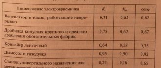
Table of losses of power transformers according to reference data depending on the rating
Most often, the problem of electricity leakage is associated with the movement of eddy currents and magnetization reversal. Under the influence of these factors, the magnetic circuit heats up, which causes the bulk of no-load losses, regardless of the load current. The development of this process occurs regardless of the mode in which the device operates.
Gradually, under the influence of certain factors, these indicators may change towards a significant increase.
Loss table XX
| Power kVA | HV/LV voltage, kV | No-load losses W |
| 250 | 10/0,4 | 730 |
| 315 | 10/0,4 | 360 |
| 400 | 10/0,4 | 1000 |
| 500 | 10/0,4 | 1150 |
| 630 | 10/0,4 | 1400 |
| 800 | 10/0,4 | 1800 |
| 1000 | 10/0,4 | 1950 |
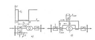
Checking the device in XX mode
To do this, perform the following actions:
- Using a voltmeter, check the voltage supplied to the coil.
- Use another voltmeter to examine the voltage at the remaining terminals. It is important to use a device with sufficient resistance so that the readings are of the required value.
- Connect the ammeter to the primary winding circuit. With its help, you can determine the strength of the no-load current. They also resort to using a wattmeter, with which they try to measure the power level.
After receiving readings from all instruments, calculations are performed that will help in the calculation. To obtain the necessary data, it is necessary to divide the indicators of the first winding by the second. Using the data from the XX experiment with the results of the short-circuit mode, it is determined how fully the device performs its actions.
Buy reliable equipment
If you need to buy high-quality and reliable equipment or any electrical equipment, we advise you to familiarize yourself with the product catalog presented in our online store. We present to our consumers a fairly large range of electrical equipment that fully comply with all existing quality standards and GOST. During the production of the equipment, only high quality components were used. Thanks to the use of components that absolutely comply with the standards, the operation of the equipment is ensured over a long period of time. The products sold by our company have been tested for full compliance with the characteristics declared by the manufacturer, which was carried out in the factory. Therefore, we can say that from us you can buy not only original, but also high-quality equipment. The electrical equipment is supplied with a warranty card, which allows consumers to rely on technical service in specialized centers.
If you are interested in any specific questions regarding the products offered, you have the opportunity to ask our consultants using the hotline number that you see on the screen. The managers of our online store will contact you as soon as possible, after which they will provide you with comprehensive information. In addition, each item that is presented on our website has a detailed description. Therefore, you definitely don’t have to buy a pig in a poke. Since our company’s employees are highly qualified and professional, we are completely confident that the advice they provide will help you make the most correct choice of equipment that will be perfect for specific purposes and cope with your functional responsibilities at a high quality level. The pricing policy of our online store of electrical equipment is democratic. Therefore, you can purchase the necessary equipment at current prices, without any unreasonable extra charges. Delivery of equipment is carried out in the shortest possible time, due to which you can accurately verify the high quality of the offered goods quickly enough. Also, importantly, the order will arrive at the specified address not only on time, but also safe and sound. We cooperate only with reliable transport companies, so we are absolutely confident that during transportation all rules and standards that apply to equipment of this type will be fully observed.
Features of the XX mode in a three-phase transformer
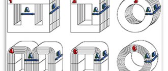
The operation of a three-phase transformer in this mode is affected by differences in the connection of the windings: the primary coil is in the shape of a triangle and the secondary coil is in the shape of a star. The current helps create its own flow.
Three-phase current in the form of a group of single-phase ones has the following features: the closure of the TGS magnetic flux occurs in each phase due to the core. If the voltage gradually increases, a breakdown will occur in the insulation and the electrical installation will sooner or later fail.
If a transformer uses an armored rod magnetic system, then the development of similar processes can be observed in it.
Calculation formula
The load factor in the presented methodology will be determined by the following formula:
K = Ea/NM*OC*cos φ, where Ea is the amount of active electricity.
What losses occur in the transformer during the loading period can be calculated using the established methodology. For this, the formula is used:
P = XX * OCH * PKZ * K² * LF.
Calculation for three-winding transformers
The methodology presented above is used to evaluate the performance of two-winding transformers. For equipment with three circuits, it is necessary to take into account a number of other data. They are indicated by the manufacturer in the passport.
The calculation includes the rated power of each circuit, as well as their short circuit losses. In this case, the calculation will be made according to the following formula:
E = ESN + ENN, where E is the actual amount of electricity that passed through all circuits; ESN – medium voltage circuit electricity; ENN – low voltage electricity.
Conclusion
Energy losses during no-load conditions of the transformer are associated with magnetic losses, losses in the primary winding and insulating layer. Work is still underway to reduce this indicator, despite the fact that the efficiency of modern transformers under high load conditions is 99%.
To reduce the rate of energy leakage, it is necessary to reduce the influence of provoking factors. To achieve this, they are constantly improving the technology for creating devices, using only durable materials, testing them experimentally.
Calculation method
Losses in transformers can be calculated using a certain method. To do this, you will need to obtain a number of initial characteristics of the transformer. The technique presented below is used for two-winding varieties. For measurements you will need to obtain the following data:
- Nominal system power (NM).
- Losses determined at no-load (idle) and rated load.
- Short circuit losses (SCL).
- The amount of energy consumed over a certain amount of time (PE).
- The total number of hours worked per month (quarter) (OH).
- Number of hours worked at rated load level (LF).
Having received this data, the power factor (cos φ angle) is measured. If the system does not have a reactive power meter, its compensation tg φ is taken into account. To do this, the dielectric loss tangent is measured. This value is converted to power factor.