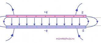
Series oscillating circuit
As is known, the simplest resonant (or oscillatory) circuits are series and parallel oscillatory circuits.
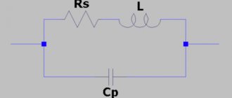
Let's consider a circuit consisting of an inductor and a capacitor connected in series (Fig. 1). When such a circuit is exposed to an alternating (in the simplest case harmonic) voltage, an alternating current will flow through the coil and capacitor, the magnitude (amplitude) of which can be calculated according to Ohm’s law: I = U/|XΣ| , where |ХΣ| -modulus of the sum of the reactances of a series-connected coil and capacitor. In Fig. Figure 2 shows the dependence of the reactance of the coil XL and capacitor XC on the circular frequency ω, as well as a graph of the dependence of their algebraic sum XΣ on the frequency ω. The last graph, in fact, shows the dependence of the total reactance of the circuit shown in Fig. on the frequency. 1. From this graph it is clear that at a certain frequency ω=ωр, at which the reactances of the coil and capacitor are equal in magnitude, the total resistance of the circuit becomes zero. At this frequency, a maximum current is observed in the circuit, which is limited only by ohmic losses in the inductor (i.e., the resistance of the coil winding wire) and the internal resistance of the current source (generator). The frequency at which the phenomenon under consideration, called resonance in physics, is observed is called the resonant frequency or the natural frequency of oscillations of the circuit, and the circuit itself, shown in Fig. 1 is usually called a series oscillatory circuit. Also from Fig. 2 it can be seen that at frequencies below the resonance frequency the reactance of the series oscillatory circuit is capacitive in nature, and at higher frequencies it is inductive. As for the resonant frequency itself, it can be calculated using the well-known Thomson formula: ωр = 1/√(LC). Rice. 1 Series oscillating circuit
Rice. 2 Dependences of the reactance of the coil XL and capacitor XC on the angular frequency ω
Figure 3 shows an equivalent circuit of a series resonant circuit taking into account ohmic losses r, connected to an ideal harmonic voltage generator with amplitude U. The total resistance (impedance) module of such a circuit is determined as follows: |z| = √(r2+|XΣ|2), where |XΣ| = ωL-1/ωC. It is obvious that at the resonant frequency, when the values of the reactances of the coil XL = jωL and the capacitor XC = -j/ωС are equal in magnitude, the value |XΣ| goes to zero (hence, the circuit resistance is purely active), and the current in the circuit is determined by the ratio of the generator voltage amplitude to the resistance of ohmic losses: I= U/r. In this case, the same voltage UL=UC=I|XL|=I|XC| drops on the coil and on the capacitor, in which reactive electrical energy is stored. At any other frequency other than the resonant one, the voltages on the coil and capacitor are not the same - they are determined by the amplitude of the current in the circuit and the values of the reactance modules |XL| and |XC| Therefore, resonance in a series oscillatory circuit is usually called voltage resonance. Taking into account the above notation for the circuit impedance, we can give a frequently used definition of the resonant frequency: the resonant frequency of the circuit is the frequency at which the resistance of the circuit is purely active (resistive) in nature.
Rice. 3 Equivalent circuit of a series resonant circuit
One of the most important parameters of an oscillatory circuit (except, of course, the resonant frequency) is its characteristic resistance ρ and quality factor Q. The characteristic resistance of the circuit ρ is the value of the modulus of the reactance of the capacitance and inductance of the circuit at the resonant frequency: ρ = |ХL| =|ХC| at ω =ωр. In general, the characteristic impedance can be calculated as follows: ρ = √(LC). Characteristic resistance ρ is a quantitative measure of the energy stored by the reactive elements of the circuit - the coil (magnetic field energy) WL= (LI2)/2 and the capacitor (electric field energy) WC=(CU2)/2. The ratio of the energy stored by the reactive elements of the circuit to the energy of ohmic (resistive) losses over a period is usually called the quality factor Q of the circuit, which literally means “quality” in English. The reciprocal of the quality factor d=1/Q is called the circuit attenuation. To determine the quality factor, they usually use the formula Q = ρ/r, where r is the resistance of the ohmic losses of the circuit, which characterizes the power of the resistive (active losses) of the circuit P = I2r. The quality factor of real oscillatory circuits made on discrete inductors and capacitors ranges from several units to hundreds or more. The quality factor of various oscillatory systems built on the principle of piezoelectric and other effects (for example, quartz resonators) can reach several thousand or more.
Fig.4 a
Fig.4 b
| Rice. 5 a | Rice. 5 B |
It is customary to evaluate the frequency properties of various circuits in technology using amplitude-frequency characteristics (AFC). In Fig. 4a and fig. Figure 4b shows two simple two-port networks containing a series oscillatory circuit. The frequency response of these circuits is shown (shown by solid lines) in Fig. 5a and fig. 5b respectively. The vertical axis shows the value of the circuit's voltage transfer coefficient K, showing the ratio of the circuit's output voltage to the input. For passive circuits (i.e. those containing amplification elements and energy sources), the value of K never exceeds one. It is obvious that the circuit resistance in Fig. 4a, the alternating current will be minimal at an impact frequency equal to the resonant frequency of the circuit. In this case, the circuit transmission coefficient is close to unity (determined by ohmic losses in the circuit). At frequencies very different from the resonant one, the resistance of the circuit to alternating current is quite high, and therefore the transmission coefficient of the circuit will drop to almost zero. At resonance in the circuit shown in Fig. 4b, the source of the input signal turns out to be virtually short-circuited by a small circuit resistance, due to which the transmission coefficient of such a circuit at the resonant frequency drops to almost zero (again due to the presence of finite loss resistance). On the contrary, at input frequencies significantly distant from the resonant one, the circuit transmission coefficient turns out to be close to unity. The property of an oscillatory circuit to significantly change the transmission coefficient at frequencies close to the resonant one is widely used in practice when it is necessary to isolate a signal with a specific frequency from many unnecessary signals located at other frequencies. Thus, in any radio receiver, tuning to the frequency of the desired radio station is ensured using oscillatory circuits. The property of an oscillatory circuit to select one from many frequencies is usually called selectivity or selectivity. In this case, the intensity of the change in the transmission coefficient of the circuit when the frequency of influence is detuned from resonance is usually assessed using a parameter called the passband. Most often, the passband is taken to be the frequency range within which the decrease (or increase, depending on the type of circuit) of the transmission coefficient relative to its value at the resonant frequency does not exceed 0.707 (3 dB).
Dotted lines in Fig. 5a and fig. Figure 5b shows the frequency response of exactly the same circuits as in Fig. 4a and fig. 4b, respectively, the oscillatory circuits of which have the same resonant frequencies as for the case discussed above, but have a lower quality factor (for example, the inductor is wound with a wire that has a high resistance to direct current). As can be seen from Fig. 5a and fig. 5b, in this case the circuit bandwidth expands and its selective properties deteriorate. Based on this, when calculating and designing oscillatory circuits, one must strive to increase their quality factor. However, in some cases, the quality factor of the circuit, on the contrary, has to be underestimated (for example, by including a small resistor in series with the inductor), which avoids distortion of broadband signals. Although, if in practice it is necessary to isolate a sufficiently broadband signal, selective circuits, as a rule, are built not on single oscillatory circuits, but on more complex coupled (multi-circuit) oscillatory systems, incl. multi-section filters.
Definition
Physics gives the following definition of quality factor. The quality factor is a parameter of an oscillatory system that determines the width of the resonance and characterizes how much the energy reserves in the system are greater than the losses that occur during a phase change by one radian. The fact is that this indicator determines the difference in forced oscillations during resonance with a certain amplitude of oscillations at some distance from the place of resonance. In this case, the amplitude of forced oscillations has no dependence on their frequency. The parameter is used not only in calculations of electrical circuits. It is also used in mechanics, acoustics and chemistry.
The quality factor of the oscillatory system in English-language resources is called Quality factor and is designated by the letter “Q”. This quantity is the main characteristic of all oscillatory systems, but it is impossible to measure this quantity, because it can only be calculated using various formulas. The degree of ideality has a direct impact on the energy loss coefficient during one oscillatory period. The smaller the value, the higher the loss of energy itself. This value is inversely proportional to the rate of decay of the system’s natural oscillations.
It turns out that the oscillatory circuit is the difference between the incoming reactance and the outgoing active one. If the oscillatory circuit has capacitance C, inductance L and load R, then the formula is used to calculate Q:
In this formula, the index 1/R corresponds to the resonant frequency of the electrical circuit ω0.
The quality factor is measured by tuning the electrical signal generator to the frequency of resonant oscillations. The resonance frequency itself is equal to the maximum output voltage of such a circuit.
Resonance frequency
When an alternating voltage with a varying frequency is applied to two CCs (parallel and series) their reactances C and L will change. Changes occur as follows:
- with increasing f, the capacitive reactance decreases and the inductive reactance increases;
- as f decreases, capacitive reactance increases and inductive reactance decreases.
Resonance - what is it?
The frequency at which the reactances of both elements of the circuit are equal is called resonant.
Important! At fres, the resistance of the parallel CC will be maximum, and the resistance of the serial CC will be minimal.
The resonant frequency formula is:
fres = 1/2π*√L*C,
Where:
- L – inductance, H;
- C – capacity, F.
By substituting the known values of capacitance and inductance into the formula for the resonant frequency of an oscillatory circuit of any configuration, this parameter can be calculated.
To determine the oscillation period of the CC and the resonance frequency, you can use the online calculator on the corresponding portal on the network. The professional program has a simple interface.
An example of the interface of an online LC circuit calculator
Resonance amplitude
In a CC, when an alternating voltage is applied from an external source, two types of resonance and a sharp increase in two types of amplitude are observed: current amplitude and voltage amplitude.
Current amplitude
The current amplitude increases sharply with voltage resonance in the series circuit (series resonance). The source of alternating EMF is connected to a circuit where the series-connected elements L and C serve as the load.
In this case, the circuit includes resistances: active r and reactive x, equal to:
x = xL – xC.
Since for internal oscillations xL and xC are equal, then for the current supplied from the generator, at resonance (when the frequencies coincide) these values are also the same. Therefore x = 0. As a result, the total resistance of the circuit will consist of only a small active resistance. This results in maximum current.
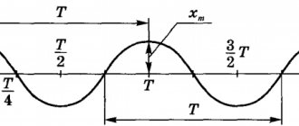
Scheme (a) and resonance curves (b) for voltage resonance
Voltage amplitude
Current resonance (parallel resonance) is a condition for a sharp increase in voltage amplitude. The EMF source is connected outside the circuit and loaded by elements L and C connected in parallel. In this case, the resonance effect is affected by the internal resistance of the generator. The voltage amplitude on the circuit is maximum when the difference between the circuit voltage and the generator voltage is small. This is possible with small Ri.
Attention! Changing the generator frequency changes the current, and the voltage amplitude on the circuit does not lag behind the voltage on the generator. If U = E – I*Ri, where E is the emf, I is the current, then at small Ri U = E.
Scheme (a) and resonance curves (b) for current resonance
The formula for determining the calculated resonant frequency for different oscillatory systems differs in the parameters included in it. Despite all the differences, the essence remains the same: the resonance effect occurs when the frequency of internal oscillations of the system and external influences become equal to each other.
Resonance effect
A striking example of the mechanical class of resonators is the spring pendulum. Professor from the Massachusetts Institute of Technology (in America), V. Levin, focuses the attention of his students on the fact that resonance is an effect associated with an increase in amplitude. An installation is used to demonstrate the phenomenon. It consists of the following components:
- electric motor;
- a mechanism that turns rotation into reciprocating motion;
- LATR – laboratory autotransformer;
- copper wire spring with a set of weights;
- spring guide.
The direction of spring oscillation is vertical. The rotation of the motor shaft causes the spring to oscillate. Using an autotransformer, it is possible to regulate the voltage. The adjustment allows you to vary the frequency of rotation of the shaft and oscillations of the pendulum. When the shaft rotation speed changes, the amplitude of the reciprocating motion remains unchanged.
Before the experiment, the elongation of the copper spring under the action of weights is measured (to estimate the resonant frequency of the spring). Changing the speed of rotation of the shaft causes the amplitude of oscillation of the end of the spring with the load to change. The amplitude increases and at the 1st hertz of frequency it becomes maximum (~30 cm).
Important! With a further increase in the shaft rotation speed, the amplitude of the end of the spring begins to decrease. This means that resonance has passed. If you reduce the voltage, and with it the engine speed, you can again observe the effect of resonance oscillations of the spring.
Spring pendulum
The quality factor of the spring Q is defined as the ratio of the oscillation amplitude of the spring Apr to the oscillation amplitude of the driving force Aavs. In this case, Q = Apr/Avs = 30/5 = 6, where Avs = 5.