What is phase rotation?
Phase alternation should be understood as the sequence in which the voltage increases in each of them. In all three-phase circuits, the voltage is a sinusoidal curve. In each line the voltage differs by 120º from the others.
Rice. 1. Voltage in three-phase network
As you can see, in Figure 1, where a) shows the voltage curves in all phase wires, shifted by 120º. The adjacent figure b) shows a vector diagram of these voltages. Both figures show the difference between phase and line voltage.
If we take as a basis that UA comes out from the zero point in figure a), then this phase is the first; in diagram b), the arrows clearly show that the order of voltage increase goes from UA to UB, and then to UC. This means that the phases alternate in the order A, B, C. This order of alternation is considered direct.
Direct and reverse phase rotation
In a three-phase network, the order of phase rotation may differ depending on the connection methods to power transformers at substations, the sequence of switching on the generator windings, due to mismatch of cable terminals and other reasons.
Figure 2: Forward and negative sequence
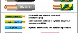
Please note that the color marking determines the sequence according to their order in the alphabet according to the first letters of the color:
- Yellow – first;
- Green – second;
- Red is the third.
Figure 2 shows the classic version of the forward sequence A - B - C (where A is yellow and is the first, B is green and is the second, and C is red and is the third) and the classic version of the reverse sequence C - B - A. But , in addition to them, in practice there may be other options, direct: B – C – A, C – A – B, and reverse alternation: A – C – B, B – A – C. Accordingly, in each of the above examples, phase alternation will start from the first one.
2.7. INSTRUCTIONS FOR USE AND TESTING OF PROTECTION MEANS USED IN ELECTRICAL INSTALLATIONS
2.7. Voltage indicators for checking phase coincidence
Purpose, principle of operation and design
2.7.1. The indicators are designed to check the coincidence of voltage phases (phasing) in electrical installations from 6 to 110 kV.
2.7.2. The indicators are two-pole devices that are briefly switched on to the geometric (vector) voltage difference of the controlled phases. If the phases of these voltages do not coincide (divergence by a certain angle), the indicator gives a corresponding light (and sound) signal.
2.7.3. The indicators consist of two electrically insulating tubular housings connected by a flexible high-voltage wire.
Housings can be detachable or non-detachable. The housings consist of working, insulating parts and handles. The working parts contain electrode tips, units that respond to the voltage value between the controlled points, and indication elements.
The working parts at the installation site of the electrode tips should not have threaded elements.
2.7.4. The operating principle of other designs that do not contain a flexible high-voltage wire, as well as their testing methods and rules of use are given in the operating manuals.
Performance tests
2.7.5. During operation, mechanical tests of indicators are not carried out.
2.7.6. During electrical tests of indicators, the electrical strength of the insulation of working, insulating parts and connecting wires is checked, as well as their verification according to consonant and counter-connection schemes.
2.7.7. When testing the insulation of the working part, voltage is applied between the tip electrode and the threaded connector element. If the pointer does not have a threaded connector, then an auxiliary electrode for connecting the test installation wire is installed at the boundary of the working part.
2.7.8. When testing the insulating part, voltage is applied between the element of its articulation with the working part (threaded element, connector, etc.) and a temporary electrode placed at the restrictive ring on the side of the insulating part.
2.7.9. When testing a flexible wire of indicators for voltages up to 20 kV, it is immersed in a bath of water at a temperature of (25 +/- 15) °C so that the distance between the place where the wire is terminated and the water level is within 60 - 70 mm. Voltage is applied between one of the electrode tips and the bath body.
The flexible wire of voltage indicators 35 - 110 kV is tested using a similar method separately from the indicator. In this case, the distance between the edge of the wire tip and the water level should be 160 - 180 mm. Voltage is applied between the metal ends of the wire and the bath body.
2.7.10. When checking the pointer according to the consonant connection circuit, both tip electrodes are connected to the high-voltage terminal of the test setup (Fig. 2.2a).
When checking the pointer using a counter-connection circuit, one of the electrode tips is connected to the high-voltage terminal of the test installation, and the other to its grounded terminal (Fig. 2.2b).
During testing, the voltage gradually rises from zero until clear signals appear. The normalized indication voltage values for both test schemes depending on the rated voltage of the electrical installations are given in Table. 2.6.
Table 2.6
VOLTAGE INDICATORS FOR CHECKING PHASE COINCIDENCE
┌────────────────────────┬─────────────── ───────── ───────────────┐ │ Rated voltage │ Indication voltage, kV │ │ electrical installations, kV ├──────────── ───────┬ ───────────────────┤ │ │according to the consonant scheme│according to the counter scheme│ │ │inclusion, no less│inclusion, no more│ ├──── ─── ─────────────────┼───────────────────┼─── ───────── ───────┤ │6 │ 7.6 │ 1.5 │ │10 │ 12.7 │ 2.5 │ │15 │ 20 │ 3.5 │ │20 │ 28 │ 5 │ │35 │ 40 │ 17 │ │110 │ 100 │ 50 │ └────────────────────────┴── ──────────── ─────┴───────────────────┘
2.7.11. The standards and frequency of electrical tests of indicators are given in Appendix 7.
Terms of use
2.7.12. When working with signs, the use of dielectric gloves is mandatory.
2.7.13. Before use, the serviceability of the indicator is checked at the workplace by a two-pole connection to a phase and a grounded structure. In this case, there must be clear light (and sound) signals.
2.7.14. If the voltage phases on the controlled current-carrying parts coincide, the indicator does not produce signals.
Why do you need to consider phase order?
The sequence of alternations plays a significant role in such situations:
- When connected in parallel, a number of devices (transformers, generators and other electrical machines) can be connected in parallel operation to increase the reliability of the system or to provide a greater power reserve. But, in case of incorrect connection, a short circuit will occur due to the connection of opposite phases.
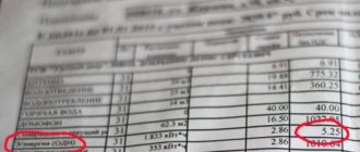
- When connecting a three-phase meter - since its operation is based on the coincidence of phases with the corresponding terminals of the device, then if the connection is not correct, a failure and spontaneous movement may occur in the absence of any load. Because of this, such a connection of the electric meter will lead to the need for the consumer to pay for kilowatts that he did not consume.
- When the engine is turned on, the sequence of phases in the network determines the direction of rotation of the engine for the electric machine. In the absence of correct phasing, the direction of movement of the elements mechanically connected to the rotor will also change. This could result in a disruption of the technological process or a threat to the lives of personnel.
In order to prevent negative consequences from phase imbalance and other mismatches, in practice, they check the alternation and install protection.
How to check?
Checking can be done in several ways. The feasibility of choosing one or another option depends on the parameters of the electrical network and the problems that need to be solved. So the alternation can be recognized using a phase indicator, megohmmeter, multimeter or by the color of the cable insulation. Consider each option in more detail.
Using a phase indicator
According to the principle of operation, the phase indicator can be compared with a conventional asynchronous motor. Let us consider as an example the most common model of a phase indicator - FU-2.
Figure 3: Schematic diagram of the operation of FU-2
As you can see in Figure 3, the phase sequence indicator has three windings that are connected to the same phases in the network or device. Between the windings there is a rotating rotor P, which drives the phase indicator disk D.
In practice, after connecting the corresponding wires to the phase indicator terminals, the worker presses the K button, which closes the circuit of the windings. Depending on the order of phase alternation, disk D will begin to rotate clockwise or counterclockwise.
On the device itself there is an arrow indicating direct alternation. If, when the button is pressed, the disk rotates in the same direction as shown by the arrow, then this three-phase load is direct interleaved. If the disk starts to spin in the opposite direction from the arrow, then the phase sequence is reversed. It should be noted that this device is not able to determine which phase is on which wire, it can only determine the order of their alternation.
Using a megohmmeter
As one of the methods for testing conductors, a device for measuring resistance - a megohmmeter - is widely used.
Rice. 4: Testing the cable with a megaohmmeter
Look at Figure 4; to implement such a scheme, you will need to disconnect the cable from the network and from the consumer. At the same time, at one end of the cable, the phases are alternately connected to ground Z, just like the metal sheath of armored cables. On the other side, a megohmmeter M is connected, one of the terminals of which is grounded, and the second is alternately connected to each of the phases. On the one where the megohmmeter shows zero resistance, there will be one wire.
Appropriate markings are installed at the ends of the wire of the same name. The disadvantage of this method of dialing is the large amount of labor costs. Since each core is grounded one by one, after which a test is performed. In this case, responsible employees must be installed at both ends of the cable. Communication must be ensured between them to coordinate actions and prevent voltage from being applied to workers.
By color of core insulation
If any device has a connection with multi-colored wires, then the phasing of the equipment can be done by color. To determine the location of the same voltages of certain phases, it is necessary to get to each cable core. If each wire has insulation of different colors, then by comparing them with the place of connection to the transformer or switchgear, you can determine where each phase is located.
The disadvantage of this method is false color marking, since the cable manufacturer does not always provide the same color for each core along the entire length of the wire. Therefore, it is still recommended to ring and mark it first.
Using a multimeter
For this method, a regular multimeter is used. It is most relevant in situations where it is necessary to include two adjacent devices in parallel operation and their buses are located nearby.
Rice. 5: phasing with a multimeter
It is necessary to compare the phase voltages in adjacent lines; Figure 5 shows an example for phases A and A1. The switching equipment must be open. Before using a multimeter, the voltage class is set on it for the line on which the measurement will be made. The probes are brought to the phase terminals, while their insulation must provide protection from voltage, and dielectric gloves are put on the hands.
If, when connecting the probes to terminals A - A1, the arrow remains at the zero mark, this means that the phases are the same. If the arrow deviates by the amount of line voltage, you are measuring opposite phases.
How and how to determine the order of phase rotation in a three-phase network?
When connecting various equipment to the electrical network, a problem that often arises is that the wires and phase markings may be incorrect, and the phase markings may be lost or erased.
If you connect the equipment incorrectly, there is a risk of serious accidents and breakdowns, since the incorrect phase sequence causes the motors to rotate in the opposite direction. It’s not worth explaining what this means in transport, on construction sites or in large-scale industrial production.
An oscilloscope can be used to determine the phase sequence, but this is not very convenient and is not always applicable to production conditions.
There are special devices: phase sequence indicators, which are electromechanical, electronic and non-contact.
These devices have many names: phase rotation indicators, phase sequence indicators, phase order indicators, phase order indicators, etc., but the essence does not change.
Electromechanical indicators
These are the most common and simple devices that have been used for a long time and are distinguished by their simplicity and clarity. They are a small three-phase motor with a rotating disk, by the direction of rotation of which the phase sequence can be determined. The most famous devices: EI5001 or I517M .
The device should be connected to 3 phases and briefly press the button. Rotation of the disk will show whether the phase sequence is correctly determined.
There is one subtlety - pressing the button should be short-term, 1-2 seconds is enough for the disk to start rotating. If you hold the button down for too long, the device may fail due to overheating.
A more modern electromechanical device is 8PK-ST850.
It is designed according to the principle of the previous one, but is equipped with standard wires, a soft case and neon phase indicators. If there is no contact with any phase, then this will be immediately clear by the absence of light on the indicator of this phase.
The disadvantages of such devices include relatively large dimensions and weight, as well as the presence of moving parts. The advantages are high noise immunity and almost zero probability of measurement error.
Electronic contact indicators
UT261A is a convenient small-sized device with LCD indicators that allows you to monitor the presence of each phase and the order of their alternation.
The device does not require an internal power source, as it is powered by the voltage being tested.
UT261B is an electronic device that, like the previous one, shows the presence of phases with neon indicators and the order of phase alternation with LEDs. The device is powered by 9 volts from a Krona battery.
A special feature of the device is not only the determination of the order of alternation of voltage phases, but also the order of alternation of motor windings. It works like this: the device is connected to an unplugged engine. The motor shaft is rotated manually and the LEDs will show the order of the winding phases - L (left) or R (right).
The advantages of the devices include ease of use, small dimensions and weight, the absence of moving parts and, as a result, greater reliability.
The disadvantages are higher sensitivity to interference and distortion in the network compared to electromechanical devices. In the case of very strong interference, the instrument may give uncertain readings, but the level of interference or distortion must be very high.
Non-contact electronic indicators
Quite new devices UT262A and UT262C , which allow you to determine the phase sequence without breaking the circuit or galvanic contact with the network.
For measurements, clips with current sensors are attached to the wires and LED indicators show the direction of phase rotation. Naturally, in this case, current must flow through the wires.
The advantages of the device include simplicity and safety of use.
The disadvantages are too high sensitivity to electromagnetic interference and nonlinear distortion. In a production environment, it is difficult to avoid this kind of interference, because nowadays frequency drives, inverters, etc., using PWM and frequency synthesis technologies, are connected to the network.
However, the devices are quite suitable for primary inputs, that is, where the level of interference and non-sinusoidality is relatively low.
In a brief review, we examined 3 main types of phase sequence indicators, which are supplied by Test instruments LLP, which is the official distributor of manufacturing plants.
Orders for devices are accepted on the Internet portal
Protection against alternation violation
To protect electrical equipment from incorrect rotation, a phase control relay is used in practice. This relay is configured to operate the engine or other device when it is connected directly. If due to some malfunction or incorrect connection the alternation is disrupted, the three-phase relay will immediately turn off the device. His work is based on the analysis of three-phase currents and voltages and subsequent monitoring of these parameters.
The connection can be made through current transformers or directly, depending on the model and voltage class of the network. Such protection has found wide application when connecting induction-type meters, electrical machines and other high-precision equipment.