Testing internal elements
Always remember that before testing, the relay must be disconnected from the power source! Even capacitors that are disconnected from the network store an accumulated electrical charge.
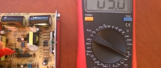
Take a multimeter and determine the resistance:
if the contact and pole are normally closed, the resistance will be zero;
if the pole and normally open contact - the resistance is greater than 0.
To test the relay acoustically, you need to connect two conductors to contacts 85 and 86. Connect the other ends of the conductors to the battery. You will hear the operating relay immediately - when the conductor and battery come into contact, clicks will appear.
There are clicks, but do the moving and fixed contacts work? Let's find out:
- Take a multimeter and attach its probes to the contacts. If everything is normal, you will hear a whistle.
- If you don't have a multimeter, then you can use a test light. In this case, an additional conductor will be needed. Connect it to the “+” contact and place it on the coil. Connect the second conductor to another contact. We connect the light bulb to “–”. When the relay is turned on, the light should light up.
The cause of non-functioning electrical equipment in the car (for example, fuel pump, heated seats, heated windows, power windows, etc.) may be a faulty relay. Let's look at a simple way to test a car relay for functionality with your own hands.
Connection diagram for 4 and 5 contact relays:
What to do if the multimeter does not have a dialing mode
Some budget electronic testers do not have a separate dialing mode with a sound alert, but they can also check the integrity of the circuit , but this is not so convenient.
For example, the fairly popular dt 830b does not have a buzzer, but there is a diode test mode, you can use it by observing the change in readings on the screen. The probes are connected in the same way as described above into the COM and V Ω mA .
If the readings on the screen during measurements differ from one, then there is an electrical connection in the area being tested. You can check the functionality of this method by connecting the probes; if everything is in order, then zeros should appear on the screen.
In multimeter models, where there are no additional functions at all, in particular in analog instruments, you can ring by switching the regulator to the resistance measurement mode - ohmmeter.
In this case, it is necessary to select the lowest available threshold - for example, 50 Ohms or 200 Ohms. Then measure according to the usual scheme described above and watch the changes in the readings on the screen - if there are changes, the circuit is intact. For home, everyday conditions, this is quite enough to find which wire is broken, determine the burnt track on the board, and much more.
That's all for me; in my opinion, this information is quite enough for anyone to learn how to dial with a multimeter, even without ever doing it before. If you still have questions or have healthy criticism or additions, be sure to write in the comments to the article, in addition, subscribe to our VKONTAKTE group - stay tuned for new materials.
In the following articles we will talk about other useful functions and ways to use a digital multimeter in everyday life, determine the phase and zero in an outlet, measure the voltage in the network and much more, stay tuned .
Design and principle of operation of the switching device
An electrical relay is a part that is used as a switch thanks to the control signals that are supplied to it through an electrical circuit. The line connected to the device is called controlled; the line through which a command is already being sent to it - the manager.
It is used in domestic conditions and in all industries to automate various operations. If a household or electrical appliance fails, you must first check the functionality of the switching element. But first it is recommended to familiarize yourself with the types and operating principles of relays.
Principle of operation
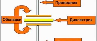
The part is an electromagnet, which includes an inductor, an armature and a contact group.
Each component is mounted on a base and enclosed in a protective housing. The armature is located on top of the magnetic system core; in the initial position it is held thanks to a spring, which has the shape of an L-shaped movable plate.
The lower part of the base is equipped with a contact group; on the contrary, the same number of contact bases is mounted. The contacts are ductile because they need to be brought out outside the protective housing to form the device terminal.
The principle of operation of the relay is based on its ability to influence conductive objects with its electromagnetic field. As soon as voltage is applied to the winding terminals, current begins to flow through the relay. When its value reaches a previously programmed value, two forces are formed in the winding, which press the armature to the surface of the coil.
Taking into account the design features, the initial position can be not only closed, but also open. In the second case, when voltage is applied, the line will open. The contacts of the device will return to their original state as soon as the signal of the required magnitude is removed from the relay terminals.
Video
You can watch the relay testing process in detail in the video.
But you can learn about how to check the wiring in a car for a short circuit or break in other useful articles on our website.
A relay is a device designed to control high power signals with low power signals. Its main task is to separate and protect the low voltage circuit with an electromagnetic coil from the high voltage circuit. There are several ways to verify that the relay is working; the most convenient, fastest and most reliable is to use a multimeter.
Types and characteristics
Depending on the element base used, relay regulators are divided into the following types:
- Microcontroller or microprocessor based. Their peculiarity lies in the inclusion of a working algorithm in the built-in chip. Used in expensive cars, such as BMW or Audi.
- Relays are based on switching relay contacts to cut off and stabilize the performance of the electrical network.
- Integrated relays are widely used in the automotive industry. The operating principle is based on solid-state switching parts or integrated semiconductors.
- Hybrid transistor-relay devices and simply transistor ones are based on semiconductor elements. They were actively used in industry until the early 90s.
Intraspecific differences
In addition to the main classification, it is worth highlighting the differences within the existing types of TTP.
The following types are distinguished:
- THREE-PHASE - capable of conducting currents of 10-120 Amperes simultaneously in three phases.
- REVERSIVE - devices built on the semiconductor principle, capable of operating in circuits with direct and alternating current. In terms of purpose and principle of operation, they are identical to single-phase ones. A prerequisite is the presence of a control circuit that protects the device from false operation. The advantages of solid-state three-phase relays include the ability to operate simultaneously in 3 phases, as well as a long service life. The increased service life is due to the presence of reliable insulation and a well-thought-out control circuit. In the process of using solid-state models there is no noise, sparks, rattling during switching and other negative factors.
- SINGLE-PHASE - products that provide circuit separation when a sinusoid passes through zero. The TSR operates in the following range - 10-500 A. Control is carried out in several ways.
Symptoms of a problem
Before checking the relay with a multimeter, you should familiarize yourself with the main signs that the part has failed.
- There are cases when, as a result of the failure of the voltage regulator, the battery boils.
- When the ignition is turned on, the control light on the dashboard does not light up (however, this can be a symptom of other types of malfunctions, for example, a contact has fallen out or burned out).
- The dynamic characteristics of a household appliance or car are reduced, especially when the engine reaches high speeds.
- After starting, the battery indicator does not go out on the dashboard, which indicates a battery problem.
- The indicators on the dashboard simply turn off if the engine speed during operation exceeds 2000 rpm.
- The brightness of the headlights depends on the engine speed. It is quite simple to verify this - you need to stand in front of the wall in the dark and turn on the headlights. The brightness of the glow will change depending on how hard you press the gas.
- The battery is regularly discharged.
These signs may indicate other malfunctions, but first of all it is recommended to check the relay regulator.
Application in car
Most often motorists have to deal with switching devices. We are talking about the generator (starter) regulator relay. They remember it when the engine stops starting and it turns out that the battery is discharged. One of the reasons for this is a malfunction of the regulator.
On older cars, to maintain a constant voltage, a regulator was used, consisting of three devices - a voltage stabilizer, a current limiter and a reverse current relay. The regulator prevents the battery from overcharging, which prolongs its service life.
It can be built into the starter brush block or performed as a separate module. Its failure may or may not overcharge the battery. In the first case, streaks will be visible on the case, the electrolyte will begin to boil away, which will lead to a voltage drop below 12 volts. In the second, the values will initially be lower than acceptable. As a result, the engine will not start.
Reasons for failure of the relay regulator
In order to minimize the likelihood of repeated breakdowns in the future, you should familiarize yourself with the main reasons for device failure.
- Short circuit in any part of the electrical circuit, including interturn short circuit of the excitation winding.
- The regulator may also fail if the diodes break down or the rectifier bridge breaks down.
- Incorrect connection or reverse direction to the battery terminals.
- Penetration of moisture or large amounts of dust into the generator and/or the regulator itself (such cases are common during heavy rainfall or when washing the car).
- Mechanical damage to the working unit.
- Natural wear and tear, end of service life.
- Initially, the quality of the purchased product is questionable.
Short circuit protection
If the insulation in the target is damaged and for other reasons, a short circuit may occur. To avoid damage to the SSR, special fuses are used. They are designed for use in combination with solid-state products.
They are easily recognized by the following specifications:
- gR - fusible inserts operating in a wide range of I. They are used to protect semiconductors. These are some of the fastest-acting devices today.
- gS - like previous fuses, they can operate in all I ranges. They are used in cases of high loads, as well as for protecting semiconductors.
- aR - melt inserts that have no restrictions on I work. They are installed to protect semiconductors from short circuits. The disadvantage of such products is their high price. That's why many people prefer more affordable B-class automatic machines.
Preparing to test the relay for functionality
Checking the relay will not take much time if all the preparatory work is done correctly.
Before you begin diagnosing the device, you need to determine the purpose of the pins of the part being tested. To do this, use the documentation supplied with the device; it contains all the diagrams and operating features, and the characteristics of the device.
There are common cases when the operating diagram is depicted on the relay body itself. Contacts are represented by dots; they are connected by an inductor, the switching elements are straight lines with a dotted line. The power supply pins are shown schematically as a rectangle.
If the relay is built into the circuit, you need to visually inspect the state of the bus and power traces on the board itself. To check the relay with a tester, you can use both digital and analog instruments. No preliminary preparation or setup of testers is required.
In addition to the tester, you need to prepare a regulated power supply. For the results to be reliable, the relay must be removed from the circuit.
The functionality test is carried out in several stages:
- winding;
- normally closed position;
- normally open state.
Then you can proceed directly to diagnosing the relay.
Operating principle
Essentially, a relay is an electromagnet. When control voltage is applied to the coil, the rod attracts the armature, thus switching the circuit.
There are three types of relays:
- with normally closed contacts;
- with normally open;
- throwing over.
When a control signal is applied to a device with normally closed connectors, they open; if there is no signal, they close. For relays with open connectors, the opposite is true. There is voltage on the winding, the terminals close, but when there is no voltage, it opens. In flip-over models there are two sets of connectors, one normally closed and the other normally open. They have a common terminal. When current is applied to the winding, the contacts switch from one position to another.
Diagnostics of windings and contact groups
The winding is an inductance coil on which wire is wound in a spiral. It is characterized by a certain resistance, which is calculated according to Ohm's law. The resistance value should range from 10 to 100 Ohms.
Diagnostics of the winding allows you to find out whether its integrity is compromised. Functionality testing is carried out in several stages:
- The multimeter is turned on in resistance testing mode. On the instrument panel this mode is indicated by the symbol – Ω, the range is set within 2 kOhm.
- One measuring wire is connected to the socket, and the second to the COM.
- The wire probes touch the relay terminals.
The resistance of the inductor can be determined by the deflection of the arrow.
Checking contact groups is carried out in two stages. First, the resistance must be measured offline, and then when voltage is applied to the coil. When checking, you will need a power source, you need to take care of this in advance.
Selection options
When buying a solid-state relay, you should pay attention to the following parameters:
- Cost - from 100 to 12 thousand rubles.
- Number of phases - one or three.
- Limit load current - from 10 to 500 A.
- Switchable voltage level. There are four ranges possible here - from 5 to 220 V (DC), from 24 to 380 V, from 48 to 480 V, from 24 to 480 V. The last three ranges are typical for devices operating on alternating current.
- Control signal - AC (80 to 280 V, 100 to 280 V), DC (3 to 32 V), resistance 0 to 560 kOhm (2 W), analog signals - current 4 to 20 mA or voltage from 0 to 10 V (constant voltage).
Abnormal voltage readings on the multimeter
If the multimeter shows low voltage in the battery, the battery will simply stop accepting charge. As a result, the car may not start, the indicators on the dashboard may stop working, and troubles may arise while driving.
If the voltage is increased, there is a possibility that the level of electrolyte in the battery bank has decreased, or it has simply boiled away. Another characteristic feature may be the formation of a white coating on the walls of the body. When recharging, the battery may begin to behave unpredictably.