We install the electrical panel ourselves.
The importance of the electrical panel in the apartment in the power supply system of the house is extremely great. The wiring will not be able to function efficiently and fully without the correct distribution of electrical energy consumers, and fire and electrical safety will be reduced to a minimum in the absence of the necessary protection elements. Of course, it would be better if specialists deal with the wiring and installation of equipment, but with some study of this issue (this article will help you with this), you can independently install the electrical panel yourself without much effort and expense, by assembling a simple electrical circuit. The main thing is to understand what power supply schemes there are, what equipment you need to choose, how to calculate electrical loads, how to distribute them correctly and evenly.
Distribution panel composition
The distribution panel consists of the following elements:
a box equipped with a door; DIN rails for mounting automation; distribution busbars connecting all conductors; groups of circuit breakers with RCDs or differential circuit breakers;
electric energy meter; wires connecting all elements.
The meter allows you to determine the amount of electricity consumed. It is installed by energy company employees who seal the device. The main switch completely cuts off power to the panel. It is usually two-pole and disconnects the phase and neutral wires supplying electricity. Its power must correspond to the sum of the powers of all energy consumers included in the apartment.
An interesting and educational video about the secrets of choosing machines and assembling a switchboard with your own hands:
Connecting reliable automation
In apartments, that is, where the electrical wiring is made according to a single-phase circuit, install one- or two-pole network releases. Consult an electrician which is better, because they come with different numbers of wires in a house or apartment
- UPS for home: types, design and operating features
What is an intermediate relay: design, principle of operation, device and application ideas (115 photos)
Homemade 12 volt power supply: selection of components and simple circuits for creating with your own hands. 130 photos of homemade universal blocks
At least superficially familiarize yourself with the insides of the packages. The main components in them are the automation control unit and the chamber in which the electric arc is extinguished. She appears at a couple of poles. When they are disengaged, an arc with a high temperature occurs, something like mini-welding.
The machine can be manually turned off if there is urgent work on the internal network. Or the contacts in it are burnt and you need to reconnect them to a free place. In automatic packaging machines there are an even number of pairs of contacts - from one to four.
If there are no free contacts, purchase a new automatic packetizer. It is advisable to have some in stock at home, they are inexpensive, but you won’t run to the store at night. Buy with operation indicators: red/green light.
How to distribute current between consumers?
At the installation stage of the electrical panel, it is important to correctly distribute electricity between consumers. Many residential electrical panels are assembled by themselves.
But at the same time you need to adhere to basic rules:
- Each consumer with an indicator above 2 kW must be registered in a separate group. To do this, the machine is fixed and the load is pre-calculated.
- If the equipment is of low power, then corresponding automatic machines are created. But you should also choose the right cable cross-section - up to three square millimeters.
- When an apartment needs devices with an increased power rating, then an automatic machine with 20 or even 32 A is used for them. There is also no need to experiment with the cable - let it be of a decent cross-section of six square millimeters.
- To create lines to the sockets, a three-core cable is used (each separately). The distribution box contains branches to each outlet.
- Lighting devices - with their own line.
- The height of the apartment electrical panel is 1000-1800 mm from the floor.
Marking
Determine at what height the sockets and switches will be located; the easiest way is to measure the lines of sockets and switches from the ceiling, because the floors in apartments are most often crooked. For example, if the height from floor to ceiling after renovation will be 250 cm, and you want to raise the sockets by 30 cm, measure 220 cm from the ceiling. If there are several sockets and switches in one group, draw a horizontal line along the level and place a mark every 7 cm (socket box size 71mm), the same applies to vertical groups.
For lovers of standards, so that it is “like everyone else” or “how they do it” - remember, they do not exist! There are requirements for children's institutions, kindergartens and schools, where sockets and switches are installed at a height of at least 160 cm. Everything else, especially in your home, you can do as you wish. For example, some make sockets in window slopes or even in the floor.
Where to start?
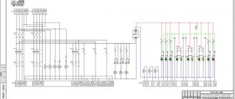
Every experienced electrician will confirm that it is much easier to begin work on installing an electrical panel and wiring, having before your eyes a floor plan indicating the intended placement of household appliances, lighting fixtures, as well as sockets and junction boxes. Having decided on the number and power of consumers, it is necessary to draw up a diagram of the electrical panel itself. A single line diagram might look like this:
In this diagram, all consumers are divided into 20 groups, for each of which the following is indicated:
- wire grade and core cross-section, mm²;
- power;
- current consumption;
- type of circuit breaker indicating the rated current.
For the uninitiated, such a diagram looks quite complicated, so you can use a simplified schematic representation of the location of the electrical panel components.
For greater clarity, the electrical panel diagram can be depicted as follows:
Or even like this:
Where
- 1 - introductory AB;
- 2 - counter;
- 3 - zero bus;
- 4 - grounding bus;
- 5–10 — AV consumers.
Having such a diagram in hand, it is much easier to figure out how to properly assemble an electrical panel.
Machines, wires, security
If you are wiring electricity in an apartment from a panel yourself, then there must be automatic circuit breakers, that is, automatic power cut-offs for a certain group of points in the home network. So, for a socket, the circuit breaker must be no less than 16 A, the cross-section of the wire connected to it is 2.5 mm². A 10 A automatic circuit breaker should be responsible for lighting; the wire connected to it and to the lighting fixtures should be 1.5 mm².
We use machines for each group of consumers
One of the most “powerful” appliances in the apartment is the electric stove and boiler; wires with a cross-section of 4 mm² must be connected to them, and their circuit breaker must be at least 20 A. All this is placed in a distribution panel, which is placed in the corridor. Important: do not use the machine more than indicated in the list below, otherwise the wire will simply burn out.
Cable cross-section – 1.5 mm², automatic 10 A, 2.5 – 16 A, 4 – 20 A.
To connect all the necessary points to the machine, you need to use a special bus and in no case pieces of wires.
Bus for connecting all points to the machine
Each panel must include an input machine (a toggle switch that de-energizes the entire apartment). This is an important point, since it is used mainly in emergency situations, for example, in case of a fire or a water pipe leak from the upper apartment.
For an apartment or any other residential premises, insulated copper wires are used.
We use only copper wires
They do not break, since aluminum ones do not withstand bending, and they also have the ability to conduct current better.
Safety regulations:
- Before installing the wiring, you must turn off the electricity.
- Do not lay the cable when it is live.
- If it is necessary to solder wires, then this must be done in special gloves.
- Before tightening the wires into the tube, you need to remove all burrs from them.
Purpose of equipment and importance of calculations
The main purpose of the distribution board is to protect the home electrical network from overloads, and the premises itself from fire
It is important to understand here that the design and calculations of all parameters must be carried out with the utmost care. For example, if the cross-section of the wiring is incorrectly calculated and the installation is of insufficient size, the load on the network can cause the insulating layer to burn
The other extreme is installing too powerful machines. In this case, electrical appliances with high energy consumption may cause the sockets to burn out.
For example, if the cross-section of the wiring is incorrectly calculated and the installation is of insufficient size, the load on the network can cause the insulating layer to ignite. The other extreme is installing too powerful machines. In this case, electrical appliances with high energy consumption may cause the sockets to burn out.
Wiring with a large cross-section that is not designed for specific conditions also leaves the network defenseless. During a load surge, protective actions may not occur because the circuit breakers will not have time to respond to critical indicators in time.
Approximate diagram of electrical panel constructionSource ul-avesta.ru
What to do first
You bought a certain number of wires from the network of a new house, completed the wiring, its ends are connected to a control panel that has not yet been built into the wall, and there are automatic machines nearby. Remember: it is better to install one automatic packetizer or RCD at the entrance to the electric meter. There is no such thing as too much protection. Next, make a plan for connecting the wires to the arranged packages.
It is advisable to relieve the network by dividing it into zones - with heavy loads and normal ones: kitchen, living room-bedroom, corridor-toilet, veranda-basement. You will get confused with packets; the instructions for them describe currents, loads, and wiring cross-sections. Methods of contact with terminals and so on.
- Reinforcing shears (bolt cutters): types, characteristics, main differences
- How a voltage control relay works: the principle of operation of the protection and the nuances of connecting a control relay for a house or apartment
What is a pulse relay: principle of operation, types, description of devices and connection diagrams. 155 photos of pulse-type relays and video installation instructions
Optimal diagram of a 380V electricity metering board for a private house 15 kW
It differs from the previous one in the presence of a selective Safety Shutdown Device (number 6), it works immediately for all consumers in the house, it is also called fire protection. The installation of an RCD at the entrance to the house is recommended by the Electrical Installation Rules - PUE.
Detailed step-by-step instructions for selecting equipment and assembly are available at this link...
Metering board diagram for a private house with selective RCD, For TT grounding system
This is the most balanced scheme that can be implemented for a remote electrical metering panel at home, simple and reliable. It is suitable for everyone, and this is what I recommend collecting.
To improve it, in order to enhance the protection of the electrical network and electrical appliances at home, you can add a surge protection device (SPD).
Electrical wiring
Surely everyone has noticed that the insulation colors of the cable cores are different colors. This is not done by the manufacturer for beauty or aesthetics. First of all, this is ease of installation and subsequent maintenance, as well as the electrical safety of the installer himself.
Wiring by color is carried out as follows:
- A yellow-green, light green or yellow wire is always ground. These are the colors that are generally accepted today.
- Blue, cyan or white with a blue stripe is always a neutral wire or a neutral wire. It should not be confused with grounding. Of course, if these cores are bridged, the equipment will not fail, but if a residual current device (RCD) is installed in the input panel, it will be constantly switched off.
- • All other colors are used as phase wires.
Wire color coding
The wiring diagram must correspond to the color marking.
It is important to remember that in order to make the wiring in the distribution box to the switches correctly, it is the “phase” that must be interrupted, which means the neutral wire (and, if present, the ground wire) must be routed so that it goes directly to the lamp, and the phase went down to the switching device. Both wires are sent from the box to the sockets, that is, both “phase” and “zero”
Both wires are sent from the box to the sockets, that is, both “phase” and “zero”.
Connections in junction boxes must be tight. For this, it is advisable to use special terminal blocks - Wago. If the twisting method is used, then it makes sense to solder such connections to obtain better contact and prevent heating of the wire.
Advice from professionals
Now it would be useful to seek advice from professional electricians who will help you more competently connect the electrical panel and simplify its operation.
When installing a distribution board in an apartment or house, it is advisable to create a diagram of all connections with clear symbols. It can be drawn or printed on paper and glued to the inside of the panel housing door. This will allow, in the event of an emergency and the owner’s absence, almost anyone to quickly turn off or turn on the power.
For ease of maintenance and repair work, all wiring groups inside the distribution board are grouped according to the purpose of the lines. Grouping can be done using insulating tape or plastic clamps. Tags with appropriate inscriptions are attached to each group. When repairing wiring, you won’t have to rack your brains about which wire is responsible for what and avoid unpleasant mistakes.
Once again we remind you of the importance of correct connection of circuit breakers - the input conductors are inserted from the top. For reliability, inspect the markings on the devices; most manufacturers place on them a diagram of the correct connection and the question of how to connect the machine in the panel disappears by itself
Model shield
With proper assembly and calculations, there should not be an increased temperature. Otherwise, you need to turn off the shield and look for the source of the problem. If this is not done, a short circuit is inevitable.
Approximately once every six months it is necessary to tighten all the screws inside the distribution board
This is especially important when using aluminum wires in the network.
Professionals recommend not sparing three places for installing a modular socket in the panel. This will allow you to connect various tools and lighting to the panel, completely de-energizing all lines.
To create a high-tech distribution panel, it is recommended to install a voltage relay in it. This device will monitor network performance and, in the event of a critical surge or drop in voltage, will automatically turn off the load. After restoring the nominal parameters, it will turn on. In this way, you can reliably protect electrical appliances that have increased requirements for network voltage.
Outdated machines - “traffic jams” Once again, pay attention to the dimensions of the case, as mentioned above, it should be “expandable”, providing the possibility of expanding the system. A more spacious housing reduces mutual overheating of elements and increases their service life.
Pulling the contact fastenings can be combined with cleaning the inside of the switchboard housing. Dirt causes the shield elements to heat up more, and dust and cobwebs can become sources of short circuits.
Basic Rules
Wiring in an apartment or house is carried out only in accordance with the PUE. But, despite the apparent severity, most of the basic rules for installing electrical wiring are not so difficult to follow. Here is a short list of them:
- during installation, convenient access to all the main elements of electrical wiring must be provided - circuit breakers, RCDs, sockets, switches and distribution boxes (boxes must not be tightly walled up);
- the installation height of the switch is from 60 to 150 cm from the floor, the installation location is on the opposite side from the one where the door opens;
- electrical wiring must be laid only vertically or horizontally; diagonal or free bending is not permitted;
- the socket is installed at a height of 30 cm (European standard) to 80 cm (accepted in Russia for safety during flooding) from the floor;
- the distance from the outlet to the gas or electric stove, heating radiator and any pipes is at least half a meter;
- The horizontal electrical wiring line is mounted no closer than 15 cm to the ceiling or floor, vertical - no closer than 10 cm to the edge of the door or window;
- the distance between parallel cables is at least 3 mm, or each cable must be in a protective casing (corrugated or armored pipe);
Cable installation should only be on terminals inside distribution boxes (socket boxes can play their role). The connection of cores by twisting, wrapped with electrical tape, is unacceptable.
As a last resort, the twist should be soldered and insulated using cambric - heat-shrinkable tubing. Be sure to take care of grounding. If it was not there, it must be mounted and connected to the common bus with a bolted connection.
Electrical panel diagram
When drawing up a diagram of an apartment electrical panel, the following should be taken into account:
- The total power of consumers of the apartment's power supply system;
- Number of consumer groups;
- Power of each group;
- Place of installation of the electric meter.
The diagram must indicate all the components of the shield, indicating the full name, rating and protection class - this is necessary for replacing components or additionally installing new ones.
In old Soviet-built houses, the wiring was not grounded; accordingly, on the electrical panel diagrams of apartments in such buildings, as in fact, there will be no grounding bus. If the house is newly built, or the building’s power supply system has been reconstructed with a grounding loop installed, then the distribution panel diagram will also include a grounding bus.
Depending on the number and power of electricity consumers, the distribution panel diagram can be simple or quite complex. But the shield assembled using it must in any case ensure safety and ease of use of the power supply system, therefore the list and location of components in the circuit is carefully thought out.
Material calculation
In addition to the fact that you need to calculate the exact number of sockets, switches, installation boxes, you also need to take care of the length of the wire for installing all the electrical wiring in the house.
Be sure to purchase a length with a margin, otherwise during the work a problem may arise when literally 10-15 cm is not enough for you to reach the end point.
We advise you to calculate the length taking into account the following rules:
- For installation boxes, add 10-15 cm + box depth to the length.
- To install lamps, add 10-20 cm, depending on what kind of lamp will be installed. Select the length so that the end sticking out from the ceiling can be hidden in the lamp, but also so that it is convenient to make the connection.
- We add 10-15 cm to the length of each segment to connect the wires to each other.
We talked about how to calculate the amount of cable for electrical wiring in a separate article. An option for the lazy is to multiply the area of the house by 2, this is the cable length needed for home wiring.
What elements does the electrical panel consist of?
Most often, the switchboard contains such components.
- VA. An input circuit breaker (or VA) is installed to protect the wiring loop. The main incoming conductor is connected to the VA terminals. Often, for convenience and comfortable use, a switch is installed in front of this device. Its installation is also rational because it makes it easy to de-energize the circuit going into the apartment in order, for example, to replace failed elements in the electrical panel.
- Electricity meter. This device comes only after VA. Its function is to calculate the energy consumed. Many people install an electric meter outside the switchboard along with the VA. For example, this could be a platform or vestibule of an apartment building.
- RCD. This element is necessary to prevent fire or electric shock. It can be one in the circuit (attached after the meter) or several of them are installed on each line where large energy consumption is expected (air conditioner, water heater, electric stove, etc.).
- Linear machine. Connecting the machine in the apartment panel is necessary to control individual lines (lighting or household appliances). Their function is to break the electrical circuit when a short circuit or overload occurs. Thus, they keep wiring and energy-consuming devices intact.
- Difavtomat. This device replaces the RCD and the machine combined. Its use is advisable if space in the shield is limited.
- Busbars for connection. These elements are needed to connect working grounding and neutral conductors.
- RackDIN. Necessary for mounting devices in the electrical panel. Not a single machine circuit in an apartment panel can do without this element.
- Tires for distribution. This part is needed for linking automatic devices, automatic devices and RCDs. It can be a working zero, or as a current conductor.
To connect a three-phase outlet, the number of elements used in the electrical panel is no different from a single-phase one. True, they use components suitable for this type of network.
Selecting the type of electrical installation
The first thing you need to start with is to decide on the method of installing the line. Today, open and hidden wiring is used. Open electrical wiring involves fastening all the constituent elements on top of finished walls (the routes are laid in special cable channels).
Open line routing
The advantage is as follows:
- the damaged area can be repaired without any problems (no need to cut wallpaper, destroy plastered walls, etc.);
- simpler installation and preparatory work (no need to tap the walls along the electrical wiring in the house);
- convenient to add new branch points.
This installation method has one disadvantage - very often it does not fit into the overall interior of the rooms since the cable channels do not have a very attractive appearance.
Hidden electrical wiring in the house is becoming more popular. In this case, wires and cables are laid in the walls; for this purpose, grooves are drilled - grooves in the walls, ceiling and floor or behind the suspended ceiling and wall cladding.
Advantage:
- does not spoil the interior of the rooms with its appearance;
- is fireproof;
- cheaper than outside.
- the likelihood of damage is much less;
- high durability of all elements.
Among the disadvantages are:
- complexity of repair and operation (to replace the electrical wiring in the house or connect a new point, you need to open the wall decoration;
- when a breakdown occurs, it is very difficult to find the exact location of the breakdown unless you use special devices, for example, a homemade metal detector;
- prohibited in a wooden house, according to PUE 7.1.38.;
- Electrical installation work requires more experience and a set of tools.
We recommend that you still opt for the latter method, since it is more durable and the entire line is not striking! When choosing high-quality components and correctly installing electrical wiring in the house, the likelihood of a breakdown is extremely low.
Option 5
In this option, difavtomats and conventional circuit breakers are used to protect groups. Automatic residual current switches (RCBOs) protect the cable from overload, from the action of short circuit current and protects a person from electric shock. Each difavtomat must be supplied with a phase and a zero. After logging out of these devices, you cannot combine zeros either. The neutral working conductors of the remaining groups, which are protected by conventional circuit breakers, are connected to the input common zero bus.
This article presents the simplest options for single-phase electrical panels. They discuss almost all protective devices, show how they need to be connected and contain descriptions of the use of one or another option. Based on your individual situation, you must develop your own scheme. Remember that it must meet all modern electrical safety standards.
FAQ
Question No. 1.
The wires will be plastered; is it possible to lay wires in certain areas with insulation that does not match the color of the intended purpose? You can lay the wires generally in one color, white or blue, whatever you have. The main requirement is that there is reliable insulation, and the cross-section corresponds to the load. In order not to get confused, be sure to put a cambric, heat-shrinkable tube on the wire at the connection points and connections, or wrap insulating tape of a color according to the functional purpose of the wire:
- Blue – zero;
- Red, black, brown – phase;
- Yellow - green - grounding.
Question No. 2. If you use sockets and switches not with bolted contacts, but with clamping ones on springs, there is no need to periodically stretch the contacts, and a break in the sequence is eliminated. So you can carry out installation by biting off the wires at separate intervals?
The spring group of contacts does not provide one hundred percent reliability; in addition, the requirements of the PUE are violated. If there is no contact on the PE wire, the likelihood of electric shock through the housing of household appliances increases. What prevents you from making loops on the wires, strip the ends without breaking the current-carrying core and insert them into the spring contacts. All rules are followed and reliability increases.
Question No. 3. If you connect wires of different sections to an outlet, is this allowed?
The cross-section must correspond to the calculated current load, more is possible, provided that this does not interfere with the compact packaging of connections in socket boxes.
Question No. 4. Is it possible to lay the grounding wire to the chandelier body at the shortest distance from the ceiling slab fittings?
Typically, the reinforcement of reinforced concrete structures is grounded, but where is the guarantee that individual elements are part of the overall circuit? It is necessary to measure the grounding resistance, why do you need these problems, drag the wire from the switchboard.
Question No. 5. There is no contact for the grounding wire on the chandelier body, what should I do?
It’s a sin to advise this, but don’t do anything. This is a deviation from the rules, but it often occurs in our reality. Make a two-wire connection, keeping in mind that children will not climb onto the ceiling, and adults will turn off the switch before changing a light bulb, there is nothing wrong. If the chandelier body does not have metal structures, is made of plastic or other non-conductive materials, then there are no violations.
Regulatory documents and rules
The requirements for installing an electrical panel are specified in GOST 51321.1-2007. The panel is a switchgear operating under voltage up to 1 kW. Its features are discussed in Chap. 4.1. 7th edition of the PUE. The requirements for the ASU in a residential multi-storey building are specified in GOST 51732-2001, and for switchboards - in GOST R 51628-2000. Since the apartment electrical panel is a low-voltage switchgear and control device, you need to refer to GOST 51321.1-2007.
Basic requirements and installation rules
GOSTs and PUE indicate the correct way to connect the panel.
The standards note several points:
the presence of a complete circuit with the rating of the circuit breaker, the type and cross-section of the cable, installed and one-time power, protection parameters of the housing shell; installation of modules equipped with a nameplate inside or outside is permitted; mandatory affixing of the “Caution Voltage” sign in the form regulated by GOST R 12.4.026; selection of cable cross-section for laying inside according to the rating of the circuit breakers;
selection of wire insulation capable of withstanding an alternating current voltage of at least 660 V; protection of bolted connections from vibrations and short circuits with disc springs, controllers, spring washers, tips; assembly of neutral conductors on N and RE buses; connecting the REN wire to the RE panel; use of terminals to protect input and output wires; performing work using screwdrivers with slots for screw slots, tools with insulated handles; cable marking with colored PVC tubes - blue/light blue (working zero), yellow-green (protection zero), red/brown (phase); marking of N and RE bus contacts according to the serial numbers of protective circuit breakers; connection of one conductor per bus terminal N or RE; designation of outgoing cables with round (line voltage from 1000 V), square (voltage up to 1000 V), triangular (control) tags.
Which case is more reliable - metal or plastic?
Metal distribution panel in a wooden house
The apartment panel is available in metal and plastic casings. The choice of material depends on the project, design specifications and financial capabilities of the user.
The metal electrical panel has a number of features:
- reliable landing on protective zero;
- high anti-vandal characteristics;
- good fire resistance;
- installed on the street or in the entrance;
- moisture resistance class IP31 – IP54.
The disadvantage of a metal case is the need for grounding. The third wire will need to be brought out from the main power supply panel of the apartment.
Plastic electrical panel near the door in the hallway
The plastic case has the following characteristics:
- suitable for interior design;
- can be built into a special niche;
- resistance to wet environments;
- beautiful transparent or tinted door;
- excellent dust resistance.
If the insulation is poor, there is a risk that the plastic will ignite and cause a fire. In this case, it is better to purchase a box made of textolite.
We cut the cables and mount the modules
Every electrician will confirm that working with a tool specifically designed for a particular operation is easier and more enjoyable. You can cut the cables inside the shield with a regular construction knife, but if you do it with a special knife with a heel, everything turns out faster and better.
After cutting the cables, you should re-label the wires, since there will be quite a lot of them and if you get tangled in them, it will take a lot of time to restore order. When feeding cables into the shield, you should leave a length that is equal to twice the height of the shield, that is, run the cable through the entire shield, and then measure out the same amount. This measure is not wasteful: the wires inside the shield do not go in a straight line, but along an intricate curved line, and it is better to have a little extra wire left than not enough.
There are no strict rules for the arrangement of modules in the electrical panel; however, electricians usually use one of two installation schemes - linear or group. In the first case, all elements are arranged one after another in the order shown on the single-line diagram: automatic input device, RCD, automatic circuit breakers, consumer circuit breakers. Among the advantages of this location option is ease of implementation, the disadvantage is that it is difficult to find the “culprit” of the emergency situation.
If a group layout of modules is implemented in the panel, the components alternate among consumer groups: AV input, RCD, group of switches linked to this RCD. Next, the next RCD and the corresponding group of circuit breakers are installed. Such a circuit is somewhat more difficult to assemble, but the problem line is immediately visible from the triggered RCD.
General information
There are many types of such equipment on sale. Prices, sizes, materials of manufacture will be found for any buyer and purpose. But first you need to understand what this electrical installation component is.
Purpose of the mounting box
Most people, when buying such equipment, pay attention only to the appearance of the product.
How it will look in the surrounding environment is, of course, important. But first of all, such boxes must meet the following requirements: But first of all, such boxes must meet the following requirements:
But first of all, such boxes must meet the following requirements:
- All installation and maintenance work is carried out under conditions that meet safety conditions.
- Metal enclosures are grounded.
- The material of the box must withstand temperature fluctuations, precipitation of all types, and solar radiation.
Plastic boxes are safer and look more attractive than metal ones. Such electrical installation devices go by different names. Some call them meter cabinets, others call them boxes. There is no single standard, and manufacturers define products in their own way. However, they all must be practical and convenient.
Most support mounting internal components using a standard DIN rail, allowing you to mount the equipment yourself. In addition to the meter, it is installed by trained specialists after receiving permission from the supervisory company.
Features of the box design
According to the rules, all protective boxes suitable for installation must comply with security levels from IP 20 to IP 65. In addition to size and color, they can be:
- Open installation.
- Secret.
- For floor mounting.
- For inline location.
- Invoices.
- Solid or collapsible.
Quality requirements
Even for such a simple-to-manufacture device as a box for an electricity meter in an apartment or on the street, high-quality execution of all its components is important. This will enable the owner to take readings comfortably and safely
When purchasing a metal cabinet, you need to pay attention to the following points:
To make the box itself, steel with a thickness of at least 1.2 millimeters is used. Thin iron will not provide sufficient strength and long-term use. Practice shows that the door of such shields is the first to sag. This violates the tightness of the structure and threatens the destruction of electrical devices installed inside. Industrial production involves testing finished samples in installations that simulate the most difficult weather conditions. If they pass the test, this means that the quality of the paint application is good and the sample will last a long time. Large manufacturers guarantee a service life of up to 15 years. Availability of a locking device. An outdoor box for an electricity meter must be selected with a lock that can be locked with a key. Its design can be any, the main thing is that there is a seal between the metal of the door and the cylinder. The thickness of the constipation is also important. The hole must be sealed. If there is a window for data control, then a seal is also needed here. Fastening must be provided with screws or self-tapping screws, since even the best glue dries out and the glass falls out. The cabinet door must be grounded. Since the first touch falls on it, if it is energized, you can get an electric shock with its help. Except for the door, the entire body is grounded
It is best if several bolts are provided for these purposes. Particular attention should be paid to the quality of seals. They are made of plastic rubber in the shape of a ring. There should be no breaks in it to avoid leakage. Semicircular bends along the edges of the door and body ensure a tight fit of the sealing gaskets, and if they break, they prevent water from getting inside.
There should be no breaks in it to avoid leakage. Semicircular bends along the edges of the door and body ensure a tight fit of the sealing gaskets, and if they break, they prevent water from getting inside.
For the prevention and safety of traffic jams
To avoid any questions about why the plugs are knocked out when you turn on a new device, it is recommended to take note of some tips:
- Before turning on new equipment, determine its rated power and compare it with the permissible load in the network;
- Do not turn on several devices at once;
- Change wiring and electrical equipment in a timely manner;
- Install special protective covers on sockets in potentially hazardous places, such as kitchens, bathrooms, outdoors;
- For children's rooms, it is important to choose sockets with special safety latches;
- At the first sign of a flood (wet spots on the ceiling and walls), turn off the power immediately.
With a competent approach, solving the problem of knocked out plugs is not difficult; the main thing is to carefully inspect all the elements of the chain and not miss the “bad” signs.
- Details about scissor lift
- How to choose a monument?
Why do you need online personnel testing?
Electrical panel assembly
When the panel diagram has been created and the electrical wires have been laid around the apartment, we proceed to assembling the panel. If desired, you can order a prepared shield, which all that remains is to install and connect the input cable.
Marking and installing DIN rails
First, markings are made of where the modules will be located and how long the slats are needed. During the fitting process, they also take into account the distance between the rows, if there are several of them, as well as the distance between the zero and ground buses. When the marking is ready, the slats are installed in the required places.
Installation and switching of modular devices
At the stage of installation of modular devices, automatic machines and additional devices are installed on a DIN rail. They are also connected to each other. First of all, they install an input circuit breaker, then voltage relays, RCDs and differential circuit breakers, which are located in front of conventional switches.
Organization of cable entry into the electrical panel
At the stage of cable entry, it is necessary to make holes in the shield. As a rule, all insertion points are provided by the manufacturer, so it is enough to squeeze out the plastic. On one side, a general network cable is installed, which is connected to the input circuit breaker, and on the other, internal network wires.
Installation of the incoming power cabinet
Probably the most important step in installing electrical wiring in a private house is connecting the elements of the power panel, through which electricity will be supplied, protection against overloads and short circuits, as well as metering of electricity supplied to residential premises.
It should be noted that first the entire installation of the electrical cabinet and switching of the wiring going to the premises is carried out, and only after that the main power is supplied.
Modern switchboards are equipped with special DIN rails that facilitate the fastening of equipment such as automatic machines, RCDs and electric meters. The power cabinet switching sequence is as follows:
The first step is to attach the input machine. Its rating must be higher than the total power of the distribution machines. Also, the wire going from it to the electricity meter, as well as from the electric meter to the distribution machines, must have a larger cross-section than the cable cores going to the distribution lines in residential premises.
It is also necessary to remember that the power line for voltage input from the pole to the house is made only by the service organization after the necessary approvals. Under no circumstances should you do this kind of work yourself. This means that wiring in a private house is a job performed by a home handyman, and supplying the power line to the input is the task of a specialist.
Installation of the input power panel
Installation of an electricity meter
The electric meter is installed after the introductory two-pole circuit breaker as follows.
The phase wire from the breaker comes to the first, and the neutral wire to the third contact. The second contact is the phase output to the distribution machines, and the fourth is the zero output, which is connected to the zero bus, which is usually provided in modern electrical panels. All blue or blue (depending on the cable manufacturer) lines going to the premises are also connected to it. This is where the advantage of color-coded cables comes into play.
When connecting an electricity meter, you can also be guided by the connection diagram, which is always present on the back of the protective contact cover.
The wire strands in the contact terminals of the meter, which has two clamping screws, are fixed as follows: first, the upper screw is tightened, then the lower one is pressed. Thus, the core is evenly and tightly located in the contact terminal, which will avoid heating.
https://youtube.com/watch?v=YK6f4Imfh0E
Distribution machines
Purchased according to the number of socket and lighting groups, as well as their currents, the machines are mounted on a DIN rail. From above, among themselves, they are all connected by jumpers. Thus, when power is applied to one of them, the voltage is evenly distributed across all.
After this, you should, without mixing up the groups, connect the wires going to the premises to the distribution machines. In this case, it makes sense to sign each of the machines, which of the groups it connects to. This will eliminate unnecessary shutdowns when replacing, for example, a lamp or socket. After all, if a problem occurs in one of the sockets, you can turn off the machine that is responsible for this particular group. Then electrical appliances in other rooms will operate as normal, and in the room where repairs or replacement are needed, the lights will even be on. Therefore, it is worth carefully considering the electrical wiring project at home.
After all the work done, you need to once again stretch all the contacts on the machines, the electricity meter and, most importantly, on the zero bus, since if there is poor contact and heating of the wire, it is the “zero” that begins to burn first.
In addition, after 2-3 weeks of operation, these contacts will need to be checked again and, if necessary, extended.
Next, you can connect the power to the input circuit breaker and proceed to the final stage of wiring installation - testing.
The simplest input without an electric meter
Final installation of the electrical panel. Connecting consumer groups
Pre-assembly and testing work allow you to install the electrical panel by placing it in a prepared niche, hanging it externally, and connecting groups of consumers. You should wait until finishing work is completed, which may contaminate the device, increase the humidity around it, or get it wet.
The procedure is as follows:
- Secure the installation process by excluding the supply of current to the equipment input. In an apartment building, it is worth hanging a special sign on the control panel or the distributor on the floor.
- Remove the protective cardboard or special cover, remove all contents from the box, take the wires out and secure them, and clean the case if necessary.
- Insert the DIN rails with installed modules inside, secure with screws or clamps.
- The protective and working zero busbars are mounted in standard places and insulated in a metal box.
- Zero protective, neutral and phase wires are divided into separate bundles, fixed with plastic clips, and the presence of markings is checked.
- The protective zero cables are attached to the PE bus; the additional length of the reserve is tightened with couplings.
- After entering, all groups of consumers from the protective bundle are connected in series, the ends of the multi-core wires are crimped with the NShVI tip, the rest are stripped with a stripper to 1 cm, the excess is cut off.
- Final marking before clamping into terminals using heat shrink tubing or cable markers.
- The metal door is connected with a green-yellow cable to the protective zero bus.
- Cables connected to the buses of group RCDs are separated from the working zero bundle and brought out into a separate bundle. They are connected to the appropriate bus with a right angle bend, they are stripped, marked and fastened as in the previous group.
- The location of the phase cables should be on the opposite side of the box from the zero side. If there are special niches in the box, they are inserted and secured, branches and bundles of wires are secured with ties.
- In accordance with the diagram, the necessary cables are inserted into each circuit breaker. Marked and trimmed as necessary, secured.
- The working zero and input phase are connected to an automatic switch or input load switch to the upper terminals.
- The correct installation and cable markings are checked according to the working diagram, and all terminals are tightened with a force of 0.8 Nm.
What are the advantages of this method
Hidden electrical installation is used during major home renovations or replacement of wiring with a new, more powerful one.
The advantage of hidden cable routing inside the walls is as follows:
- The interior of the rooms does not deteriorate, because... electrical wiring will be hidden under a layer of plaster or in plasterboard partitions.
- Increased fire safety of housing if the walls are concrete and not wooden (or, for example, made of plaster or other non-combustible material). This is due to the fact that when the insulation ignites, the fire will not spread further due to the lack of oxygen and flammable materials.
- Increased service life of the electrical network due to reliable protection of the cable from ultraviolet and mechanical influences.
Disadvantages include the complexity of installation compared to the open method, as well as the complexity of repair and maintenance of hidden electrical wiring. The last two disadvantages are due to the fact that all wiring elements are hidden under a layer of plaster and access to them will require destruction of the wall finish.
To summarize, it should be noted that, nevertheless, for permanent housing, this option for laying cables is correct and reliable. As for bathhouses, garages, log houses and other buildings, it is recommended to install open electrical wiring.
We've sorted out the advantages, let's move on to the main question of the article!
Types of electrical panels
The manufacturer produces various types of shields, both for indoor and outdoor installation. Panels for outdoor installation are attached with dowels directly to the wall of the building. If the surface is made of wood (fire hazardous), then a non-combustible material, for example, asbestos, is placed between the surface and the shield. Such shields are installed in places where they do not interfere with normal human life. However, the location must be accessible and convenient to use. The outer shield rises 12-18 cm above the wall surface and this factor must be taken into account when determining the installation location.
The panel for internal installation is designed for installation in a specially prepared niche. This type of shield is always at the same level with the surface, therefore, it does not pose any danger to normal life.
The body of the shield is made of either metal or plastic. The size can be selected to suit any specific conditions.
As a rule, choose a shield of the appropriate size. It must freely fit all circuit breakers, all RCDs and at the same time there must be enough space for placing wires. Apart from this, nothing should interfere with the connection.
It is very important to decide in advance on the number of machines and select an electrical panel of appropriate dimensions. At the same time, we should not forget that it is possible to expand the electrical network
In this case, there should be room in the shield for at least two machines.
Possible ways to lay the wire
Replacing old wiring in a panel house begins with drawing up a new diagram. Also, replacing electrical wiring is divided into two options: partial or complete.
If it is necessary to completely replace all cables in a panel house, then a new circuit should be made. To do everything correctly, a specialist will need an old circuit. The new diagram will serve as step-by-step instructions for performing electrical installation work.
First you need to determine where the load will be. For example, the kitchen typically consumes the most electricity. If we talk about an ordinary room, then one or two sockets per 5 square meters is enough. Considering the needs of the kitchen, the same room will need four sockets. Also, we should not forget that for devices with high electricity consumption it is necessary to draw separate lines from the switchboard. Some household appliances require a copper cable with a cross-section of up to 4-6 squares.
Another room that requires special attention is the bathroom, because it is characterized by high humidity. Therefore, sockets in the bathroom should be connected through a differential circuit breaker or RCD
According to the PUE chapter 7.1. clause 7.1.48 its operation current should not be more than 30 mA. Also, an RCD must be installed to protect individual electrical appliances that are the most dangerous from the point of view of electric shock - a washing machine, a water heater, a hydromassage box, a hydromassage bathtub. In the kitchen there is a dishwasher and an electric oven.
When replacing electrical wiring in a panel house, several methods of laying a new cable are used:
- in ceiling slabs;
- under the ceiling covering;
- on the walls - under plaster, under drywall;
- on the floor in a screed.
The most common method of laying cables is to lay the cable under plaster. In order to carry out installation, holes must be made into which the cable will be laid and secured. After installation, a layer of plaster is applied over the cables. Using this method, you can stretch several lines in one groove. You can also lay cables separately for lighting, various appliances, air conditioners, and other heating devices.
It is ideal to lay cables along old channels, because then you can lay the wires without gating and save time. Therefore, it is advisable to use the paths along which old cables were laid. You can mainly use places where aluminum cables have simply been plastered, for example in the joints between the wall and the ceiling. Seams are places where it is easy to install new wiring.
When replacing old cables, you should remember that the channels in which they were located can be used to bring a new copper cable to an outlet or switch. However, the channel can only be used if the fittings are in the same places and if the old cable can be pulled out during dismantling.
In most cases, it is very difficult to find and use channels, so some experts recommend not wasting time on long searches and cleaning channels. Therefore, for horizontal installation in a panel house, it would be more expedient to stretch the cable along the upper joint between the wall and the ceiling. In this place there is usually a gap that is either plastered or filled with cotton wool.
An alternative option is to run electrical wiring along the ceiling and make grooves only in places leading to sockets and switches. You can hide the cable attached to the top by making a suspended or suspended ceiling.
When replacing electrical wiring in a panel house, you must first determine whether the replacement will be partial or complete. It is also necessary to use old channels. In order to carry out this work you need to have a good tool. However, it is preferable that the replacement of electrics in a panel house is carried out by a specialist.
Important! Remember that it is impossible to make horizontal grooves in the load-bearing walls of panel houses. This could cause the wall to collapse
This is also prohibited by various regulatory documents, for example, Decree of the Moscow Government of February 8, 2005 N 73-PP “On the procedure for the reconstruction of premises in residential buildings on the territory of the city of Moscow.” and Government Decree No. 508 (Clause 11.3 and 11.11 Appendix No. 1).
Making a diagram of the electrical wiring in the apartment
The main mistake of novice masters is incorrect planning of the upcoming work. When drawing up a network diagram, you cannot estimate the location of lamps and switches “by eye”; it is necessary to provide for every little detail so that the apartment does not have to be overgrown with tees and extension cords. Therefore, there is no way to do without drawings and calculations.
Do-it-yourself electrical wiring in an apartment: step-by-step instructions for drawing up a diagram:
1. Draw a general plan of the apartment, mark the location of windows and doors.
2. We schematically arrange furniture, plumbing fixtures and household appliances. Don’t forget about large accessories so that a mirror or picture does not end up in the place of the planned socket or switch. For greater clarity, electricity consumers can be highlighted in red. For example, like this.
3. We simplify the drawing: we remove furniture and other items that do not need to be connected to the network, and at the location of electrical appliances we mark sockets (single, double - it all depends on the number of consumers).
4. For convenience, we recommend thinking over a schematic designation for all network elements or using a hint.
5. As a result, we received the power part of the electrical circuit in the apartment.
6. Now let's start arranging the lighting fixtures. Typically, chandeliers are placed in the center of the room. To determine the location of the wires for them, you need to measure and halve the length and width of the room and mark the intersection of lines from these points on the diagram. In rooms with irregular geometry (L or U-shaped), you need to divide the room into 2 or 3 parts and find the center in each section. If additional lighting is provided with a network connection without the use of sockets, mark these devices on the diagram as well.
7. It remains to think about the location of the switches. It is clear that they will be located at the entrance to the room or near the zone lighting devices; the main thing here is to take into account which way the door will open, so that turning on the light does not turn into a game of touch in complete darkness. Switches are conveniently located on the inner wall of the room (with the exception of the bathroom and toilet).
The result of the preparatory work will be a general drawing, which will combine the plan of the power line, the layout of switches and lighting fixtures.
By the way, if you are not familiar with drawing, but you are familiar with a computer, you can make all the calculations and planning in special programs, for example “Electrician”, “DIA”, “sPlan”, “AutoCAD”, “Visio”.
Preparatory activities
Selecting the main parameters of the electrical network of your apartment
- The choice of cross-section and material from which the electrical wiring in a one-room apartment will be made, and its layout largely depend on the type of installation and the total power of all connected devices. Therefore, first of all, we should draw up a plan for the location of sockets and the lighting network. In this case, you should be guided by the norms of the “Rules for the Construction of Electrical Installations” (PUE) and basic concepts of convenience.
- Installation of switches in the bathroom is prohibited
- It is prohibited to install sockets without RCD circuit breakers in the bathroom.
- Switches in rooms should be located near the door on the door handle side.
- Sockets in residential premises can be located based on their ease of use. In this case, the recommended values are a height of 0.3 to 1.8 meters.
- Switches are usually located at a height of 0.6 - 0.8 m.
- The next important step is choosing a wiring diagram. The method of open wiring in boxes or hidden wiring in walls can be used. Each of these methods has its own advantages and disadvantages. So the advantages of open wiring include:
- Possibility of installation without making repairs to the room. You simply install an additional box under the ceiling, into which the wiring is subsequently laid.
- Installation time is significantly reduced. So, with the right approach, all the wiring in a one-room apartment can be replaced literally in one day.
- Ease of carrying out repair work and subsequent installation of additional electrical receivers.
- But hidden wiring has several more advantages:
- According to the PUE, significantly lower requirements are imposed on hidden wiring. As a result, it is not always necessary to use additional protection against mechanical and thermal damage. And there is no need to buy additional boxes for it. Thanks to this, the issue price is significantly lower.
- Hidden wiring with the same wire cross-section has slightly higher tolerances for nominally permissible currents and overload currents. This is achieved due to better heat transfer performance.
- Hidden wiring does not spoil the appearance of your apartment at all and does not take up the already small space of the apartment.
- Based on all this, we can conclude that open wiring is chosen only in exceptional cases. For example, when the repair has already been completed, but they forgot to replace the wiring. Or when wall gating is extremely undesirable due to the dilapidation of the building. In other cases, the best option is, although more labor-intensive, the option of hidden wiring.
Calculation of the electrical network of a one-room apartment
First of all, we need to calculate the rated load of all your electrical receivers. To do this, we use a simplified formula; where P is the rated power of electrical appliances, U is the rated voltage of the electrical network (for a single-phase network it is 220V), and I is the rated current of our electrical network.
- Based on this formula, an electrical appliance with a power of 1 kW consumes a current of 4.55 A. To simplify the calculation and create a certain reserve, we take it equal to 5A.
- When calculating your electrical network, take into account only realistically possible situations of its use with maximum load. You should not rely on the fact that you will connect four 2kW heaters in one room at once. After all, the probability of this is quite low. And the electrical wiring diagram in a one-room apartment will become significantly more complicated and will increase in price from such a calculation.
- Now let's start choosing the wire we need. This should be done in accordance with clause 1.3 of the PUE. But considering that our loads are not large and we do not need ultra-precise calculations, we make an approximate calculation. To do this, we assume that a cross-section of 1 mm2 copper wire has a carrying capacity of 10A, and an aluminum wire has a carrying capacity of 5A.
The next defining point for us in the PUE is clause 6.2.2. It states that group internal power supply networks must be equipped with circuit breakers with a rated current of no higher than 25A. Based on this, we should divide the loads in the apartment in such a way as to divide them into groups of no more than 25A each.
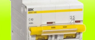
Design of a standard circuit breaker
For example, we will use the BA47-29 series switch as the most popular switching device with an affordable pricing policy. Before you learn how to properly connect a circuit breaker to a single-phase network, you need to consider its design.
The BA47-29 series circuit breaker consists of the following elements:
- A copper terminal connected to a fixed power contact. Most often, the supply wire is installed exactly in this place.
- The movable contact, which makes the switching, and the copper stranded conductor, has a sufficiently large cross-section.
- Arc chamber.
- A special thin plate with a hole through which gases formed after the arc escape.
- An electromagnetic release, presented in the form of a simple coil. The stranded conductor from the moving contact is soldered to the coil.
- Plastic, fully dielectric handle.
- A bimetallic plate that acts as a thermal release. The plate is located immediately behind the reel.
- A special screw for adjusting the bimetallic plate. The screw is not installed on all models, and adjustment is made at the manufacturer.
- The lower copper terminal, from which the conductor goes directly to the consumer.
A three-phase machine has a similar design, but instead of one terminal, it uses three, isolated from each other.
Connecting sockets and switches
This stage is quite simple; you need to connect all the sockets and switches in the apartment. For this purpose, socket boxes and special boxes are installed in the grooves. We recommend that you “plant” these elements on alabaster, because it quickly and reliably sticks to the wall.
There is no point in writing the same thing several times, so we offer a list of articles that you need to read:
- How to install a junction box in a wall
- How to connect a European socket
- How to install a light switch
- How to connect a switch to the network
Selection of electrical installation equipment
Before starting installation, you need to buy the electrical panel itself and all the electrical installations and devices that will make up its contents. It should be taken into account that each item occupies a certain number of mounting spaces on a DIN rail - a metal strip 3.5 cm wide. One or several DIN rails can be located in one box.
One “mounting point” includes a section on the profile 1.75 cm long - a module. The passport of the electrical panel must indicate how many modules it is designed for.
Three devices are fixed on one DIN rail: the first two occupy 3 modules each, the third – one module. It is not recommended to leave spaces between adjacent devices to save space.
Before choosing a shield, you should add up the number of all modules, and then add to the resulting sum several places that may be useful in the future. As an example, let’s calculate which box is needed for a 1-room apartment.
Using the diagram, we determine how many modules each device occupies: 4-pole input circuit breaker - 4 spaces, counter - 6, RCBO - 2 x 2, circuit breakers - 4. The result is 18 modules
For 18-20 seats, an electrical panel with 24 modules is suitable. But if the apartment is large, and in the future you plan to purchase new equipment, install a heated floor, or make repairs with replacement wiring, then it is better to purchase a box with 36 seats.
If you want to simplify further work, maximize network protection, and make the arrangement of modules convenient, try to choose a panel with a complete set, and this is:
- removable frame with DIN rails;
- entry holes and holders for fastening cables;
- two tires, working and protective zero - with stands and installation sites;
- set of fastenings for installation;
- organizers for wires.
Shields can be metal or plastic, built-in or mounted.
Let's look at how they differ fundamentally.
Experienced electricians recommend working with one shop. The advantages of purchasing from a large supplier are a large assortment of goods and a guarantee of receiving original products and not counterfeits. Therefore, it is better to purchase both the shield and the rest of the electrical installation products in one place.
In addition to the metering device and protective devices, you will need:
- combs for several poles with end caps - to connect modules to each other, simplify installation and save space;
- 2-3 meters of PV1 wire with a cross-section similar to the input cable and color-coded insulation;
- zero busbars or cross-modules for group RCDs;
- clamps and ties for organizing conductors;
- limiters for DIN rails;
- plugs for masking empty spaces.
If financial capabilities allow, then it is better to select equipment from one trusted manufacturer - Hager, ABB, Legrand, Schneider Electric. Devices of the same brand are easier to install, and the shield will look much more aesthetically pleasing.
Everything is ready for installation
So, the diagram has been drawn up and understood, the components have been prepared - nothing prevents you from starting assembling the electrical panel. First of all, the location of the shield is selected, on which the device is attached, as a rule, with self-tapping screws or clamps. The electrical panel housing is usually located near the entrance to the house or apartment - in the vestibule or hallway. If the owner has expressed a desire to hide the panel in the wall, and the wall turns out to be concrete, you can use a false wall or a plasterboard ledge: the area of the room may be slightly reduced.
When choosing a place on the wall to install an electrical panel, you should take into account that the distance from the device to the nearest doorway should be at least 15 cm, the distance to the floor - 1.5–1.7 m. If necessary, the owner of the home or a called electrician should be able to easily reach the panel : It is strictly prohibited to place the device inside cabinets or other furniture. The device should be located away from gas pipes and flammable materials.
To prevent the electrical panel from being too large or small, you can first determine its size by knowing the dimensions of the components that will be located in it. For example, the width of a standard single-pole circuit breaker is 17.5 mm, a two-pole circuit breaker is 35 mm, and a three-pole circuit breaker is 52.5 mm. The remaining components have the following dimensions:
- RCD single-phase two-module - 35 mm;
- Three-phase four-module RCD - 70 mm;
- single-phase two-module difavtomat - 70 mm;
- terminal block on DIN rail - 17.5 mm (1 module);
- counter (6–8 modules) – 105–140 mm;
- voltage relay of 3 modules - 52.5 mm; This is not a mandatory element of the shield, but when used, you can protect equipment from power surges or sags, and save household appliances such as a refrigerator, TV, computer and other electronics from failure;
- DIN rail socket (3 modules) - 52.5 mm.
The modules are located on the so-called DIN rail - a special metal plate 35 mm wide. The socket is not one of the required elements, but may be useful during repair work. If, when summing up the number of components, it turns out that a panel with 20 modules is needed, then it would be reasonable to install an electrical panel with 24 or even 32 modules - who can know how many household electrical appliances will be added to the house in a year, two or five?
Minimum requirements for switchboard design
In addition to the importance of preliminary calculations, which we talked about above, when creating a shield diagram, it is necessary to take into account some nuances. In general, they do not require strict implementation, but when introduced into the design, they greatly increase its reliability and ease of use.
On the one hand, you need to strive for simplicity of the device, on the other, do not neglect the advice of experienced specialists. First of all, this concerns the division of connections into several power lines. In an emergency, this approach allows you to quickly locate the location of the breakdown. An important point with several lines is the possibility of only partial loss of energy supply to the room.
This separation rule fully applies to circuit breakers. The optimal connection of machines in the distribution board is carried out according to the following scheme - each room separately. In this case, it is desirable that a separate circuit breaker be installed on the line of lights and sockets.
Shield with digital sensors
The main connection of the machines in the panel is made through one central switch. Don’t forget about appliances with high energy consumption – cooktops, washing machines and the like. All of them are connected to the network through a separate machine.
Contact connections
When using intermediate distribution boxes in the wiring diagram, you should remember that the branch contact connections in these boxes are the weakest point of the wiring.
If you do not ensure reliable contact connections of conductors in distribution boxes, then soon, when load currents flow, these contact connections may be damaged
Therefore, it is very important to choose reliable connectors (terminal blocks) or to ensure the connection of conductors in junction boxes by soldering or welding
Wiring in the house, connecting wires by soldering or welding
As for the installation of intermediate distribution boxes, in this case they are very often hidden under a layer of plaster so that they do not stand out. From an aesthetics point of view, this is acceptable, but if there is a need to inspect contact connections or troubleshoot electrical wiring, it will be difficult to find the location of the box. Therefore, it is necessary to mark the locations of distribution boxes so that if necessary, they can be easily found.
Conclusions and useful video on the topic
Video #1. Electrical panel assembly option:
Video #2. Assembly instructions and recommendations for a 72-module panel:
You can assemble the electrical panel yourself, but checking the installation and connection by a qualified electrician is mandatory. Without an appropriate conclusion, the organization supplying the house with electricity will simply block the line.
Would you like to talk about your own experience in electrical installation work? Do you have useful information that could be useful to independent novice electricians? Please write comments in the block below, post photos and ask questions about the topic of the article.
Two types of apartment electrical circuits
In any residential premises there are two types of electrical current circuits:
- Power electrical circuit, which also includes the lighting circuit;
- Low-current electrical circuits. This is telephone wiring, television antenna cable(s), apartment computer network.
Power and low-current electrical circuits differ not only in the magnitude of the currents, but also in their sensitivity to various types of electrical noise. The power electrical circuit belongs to insensitive networks, in contrast to low-current electrical circuits.
To minimize the influence of some types of circuits on others, you need to follow the recommendations for electrical wiring in the apartment. Here we will dwell in more detail on independent wiring of low-current networks.
how to lay low-current cables in an apartment
Conclusions based on the results of the work done
Now it makes no sense to talk about the amount of my financial expenses. Any costs always depend on the quality of the product, the manufacturer of the automatic protection elements and other parts required for assembly. I can only say one thing: the savings on specialist labor costs amounted to about 10,000 rubles. The whole job (I had no such experience) took a total of about 5 hours. Again, the amount saved can be many times greater. It largely depends on the region, average prices and salaries in the city. However, even saving a small amount is worth doing all the work yourself. And experience will never be superfluous.
The editors of Homius.ru invite home craftsmen and craftsmen to become co-authors of the “Stories” section. Useful first-person stories will not only be published on the pages of our online magazine, its authors will receive a small financial reward.
Next STORIES How I built a barbecue gazebo with my own hands: the experience of a Homius reader
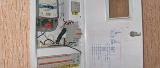
Apartment panel. Replacing machines and installing RCDs
Apartment panel , how to replace machines and install an RCD in the apartment panel? In the previous article, I replaced the CO-505 meter in the apartment panel with a Mercury 201 meter. Now we need to replace the machines and install an RCD in the apartment panel ; this must be done for several reasons. The photo below shows the apartment panel and the diagram of the panel from the developer at the time of delivery of the house.
How I assemble power shields for private houses and apartments is described in this article https://elektroschyt.ru/sborka. Main stages of assembly, electrical equipment, tools, documentation, etc.
Why do you need to change the automatic devices in the apartment panel and install an RCD? Because the apartment plan was assembled by the developer with gross violations, namely:
Firstly , the cross-section of the PPV input wire (commonly called “noodles”), which comes from the floor panel to the apartment panel, is 4 sq. mm. and on such a wire, to protect it, an input circuit breaker of no more than 25A is installed, and the developer installed an input circuit breaker of 40A in the apartment panel, i.e. It turns out that in case of high load in the apartment, our input wire will melt, and the 40A circuit breaker will not turn off. Therefore, it is necessary to install a 25A input circuit breaker in the apartment panel to protect the PPV wire of 4 sq. mm;
The significance of the RCD in the brush
The RCD must be in the electrical panel. In addition, all outlet and power lines must be under RCD control. Principles for selecting RCDs:
- For socket and power lines, an RCD is used, which has an infected response current of 30 mA. The rated operating current should be one step higher than that of the machine.
- In rooms with high humidity (hot tub, bathroom, washing machine, electric heated floor) there should be a 10 mA RCD in the outlet lines.
- In the diagram you can see that under one RCD it is permissible to install 2-4 lines with protective circuit breakers. It will be considered a group RCD. It is important to control - the operating current of the RCD must be equal to or greater than the total value of the ratings of the circuit breakers of the connected lines.
- Differentiated circuit breakers, which simultaneously perform the functions of an RCD and a circuit breaker, are not economically justified. Experts recommend connecting them separately. The use of difavtomats is justified only if there is not enough space in the electrical panel or protection of very important lines (warm floors in the bathroom).
After drawing up the diagram, it is better to show it to an experienced electrician, who will point out the pitfalls and make recommendations.
Do-it-yourself circuit diagram for connecting a machine in an electrical panel: advice from experienced electricians
It is very difficult to imagine a modern apartment without various electronics, which create some inconvenience with connection and high load on the electrical network. To increase electrical safety and reduce load, you should consider separate control of devices and install a control unit in the electrical panel of the house. The laying of cables and the correct layout of the electrical panel can be done independently in the apartment, but as for completing the work, you cannot do without a specialist, since you need to have an understanding of the structure of the distribution panel, various standards, diagrams and be able to make connections.
Requirements for electrical panels
Choosing and purchasing an electrical panel is a very important and responsible matter, since not only the ease of use of electrical appliances, but also the safety of the home depends on this choice. There are certain requirements for shields and their installation, which are specified in GOST 51778-2001 and PUE . Below you can read a list of these requirements and rules regarding the shield and its installation:
- electrical panels must be filled out in accordance with the technical documentation that comes with them, which reflects the number of installed machines and their rated current;
- the shield must have an electrical safety symbol indicating the voltage (220V or 380V);
- The shield must be made of non-flammable material and have a coating that does not conduct current. It can be plastic or metal coated with special paint;
- it is necessary to make connections inside the panel, making markings on the wires that indicate the groups of connected devices;
- jumpers between machines are made using special bus drives;
- the doors and the panel body must be grounded. It is also necessary to provide ears or some other element on the doors so that the inspection organization can seal it;
- When buying a shield, check the technical passport, which will reflect: the type of shield, name of the manufacturer, certificate, GOST, rated currents of the input and protective devices of the RCD, voltage and frequency, rated current of the shield, rated operating currents of the RCD devices, degree of protection, class of the shield, instructions by connection, weight and dimensions.
If you adhere to the above requirements, as well as the requirements noted in GOST and PUE, then you will be able to buy, install and connect the panel at home without unnecessary difficulties. In addition to this knowledge, you will also need to have on hand an electrical diagram of the control panel so that no difficulties arise when housing office employees accept work.
Drawing up an electrical panel diagram
An important step in installing an electrical panel is creating its diagram. There are several explanations for this. Let's say, if you plan to repair or modernize the wiring in your apartment in the future, using the diagram you can quickly establish what each machine and part in the panel is responsible for. You will also need the diagram when accepting work as an electrician . In addition, connecting wires with such a diagram on hand is much easier. You can either draw it manually or in specialized programs, and then print it.
The electrical circuit is created in several stages. The first step is to find out what kind of electrical system is in the house, then divide all points of electricity consumption into several categories. After this, based on the existing data, a shield diagram is created. It is extremely important that the diagram used symbols, which are described in detail in GOST 21.614 “Conventional graphic images of electrical equipment and wiring in the original.”
So, as mentioned above, all work begins with determining the power supply and grounding system in the apartment, since the connection of the panel will depend on this. You can find out by looking at the sign on the floor or by going to the housing office. Often, three systems TN-C, TN-S, TN-C-S are installed in residential buildings.
It is worth immediately noting that the first system was created according to old GOST standards and was used in houses that were built before 1998. The TN-C system is represented by two-core copper or aluminum wiring. A three-phase cable (L) with one conductor PEN, in which ground and neutral were combined, went to the floor distribution board. The last two systems are used in modern homes. A three-core copper wire is laid in the apartment, and a cable with three phases (L), neutral (N) and PE ground (S) is connected to the switchboard.
Breaking it down into points
After this, the points are divided into several groups for connection. Many people wonder: why all this? Yes, very simple. This way you can use materials more economically and simplify the installation of the electrical panel. You can group as you wish. You can combine living quarters under one machine, hang a boiler on another, air conditioning on a third machine, etc. Moreover, each group needs a machine gun with its own characteristics .
For sockets you need 20A circuit breakers, for lighting systems and switches - 16A circuit breakers, for an electric stove - from 32A, for a boiler, washing machine and air conditioner - 25A. By the way, it is worth considering that sometimes it may be necessary to install additional 25A and 40A circuit breakers on sockets, lighting and switches.
Once you have clarified the power supply and grounding system of the house, and divided the connection points for electrical appliances into groups, start drawing the diagram itself. If you have all the necessary data, its creation does not take much time. Again, it is worth considering that you have concepts with symbols from GOST 21.614 . Having finished with the circuit, you can begin connecting work. Having the appropriate experience, installation will not take you much time.
Installation of electrical panels
Before you begin installing the electrical panel, you need to do two things. The first is to purchase the necessary materials, the second is to arrange a place for it. Now let's talk about everything in order and start with choosing a shield.
It’s worth noting right away that shields can be built-in or wall-mounted , and their choice depends on several factors. If the wiring is hidden, then pay attention to the first type, and if it is open, then to the second. At the same time, do not forget that new apartment projects provide a special niche for shields. As for apartments in old buildings, there is no such thing there and therefore you will have to hang a hinged panel. If it doesn’t really fit into the interior, then it can be disguised using drywall. You can also make a niche in the wall. To do this, you need to be sure that the wall is not load-bearing.
Secondly, the dimensions of the electrical panel depend on the number of installed machines. According to GOST, there are shields for 6, 12, 18, 24, 30 circuit breakers or 6, 9, 12 threaded fuses . By the way, you need to take the shield with a reserve. If you planned to install 12 machines according to the scheme, then it is recommended to take a shield for 18. This way, you can protect yourself from additional expenses in case of installing additional machines.