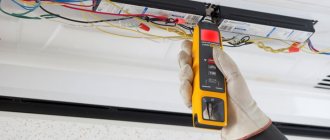
Possible malfunctions of capacitors and methods of checking using improvised means and instruments are considered. As repair practice has shown in recent years, the largest number of equipment failures occurs due to the fault of electrolytic capacitors. At the same time, there is a decrease in the number of failures due to the fault of other components.
The main types of capacitor faults and methods for identifying them will be listed here. It is believed that the main types of capacitor failures are breakdown and breakage; in fact, there are more of them.
Theory
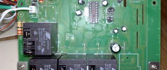
Very often, when repairing computers and computer equipment - in power supplies, computer motherboards, video cards, monitors, printers and other devices - you can find damaged, swollen capacitors in which electrolyte has leaked, and their housing is destroyed.
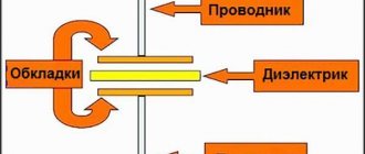
Capacitors are rolls (or stacks) of foil separated by a dielectric. In electrolytic capacitors, one electrode (anode) is the foil, and the other (cathode) is the electrolyte. A thin oxide film deposited on the anode acts as a dielectric. To understand the reason why capacitors fail, let's draw up an approximate equivalent circuit of a capacitor.
Thus, the capacitor has both active resistance r (equivalent series resistance or scientifically ESR), and leakage resistance R, and inductance L due to the coiled sandwich. The convention of the circuit is that in fact the circuit is a “long line”, the calculation of which is extremely complex.
Dial-up function
How can you check the resistor with a multimeter for serviceability? A common method is dialing. The switch position for this mode is indicated by a diode icon with a signal. The sign of the signal can be different, the upper limit of its response does not exceed 50-70 Ohms. Therefore, it makes no sense to ring resistors whose values exceed the threshold. The signal will be weak and may not be heard.
When the circuit resistance values are below the limit value, the device emits a squeak through the built-in speaker. Continuity testing is done by creating a voltage between the points of the circuit selected using probes. For this mode to work, you need suitable power sources.
Why does a capacitor explode?
The fact is that these capacitors are in the pulse power supply circuit and serve to smooth out ripples with a frequency of tens of kilohertz. In principle, due to ripples, alternating current flows through the capacitors, which slightly heats the internal resistance. At low frequencies this heating is small and the capacitor is cold. Boiling occurs when the power released is greater than the power dissipated. So why does heating occur that causes the electrolyte to boil and explode, and what role does inductance play in heating?
In pulse circuits, if you look at it with an oscilloscope, you can see that at the moment the transistors switch, a damped oscillatory process occurs, and the overshoot amplitude is very significant, and the frequency of the oscillatory process is high. The high-frequency component is well transmitted by the capacitance, and it is also the main reason for heating the capacitor. What does inductance have to do with it? And inductance is the cause of oscillations, because it is part of the LC oscillatory circuit. Therefore, the greater the parasitic inductance of the capacitor, the more energy of the high-frequency oscillatory component is released inside the capacitor. To avoid an explosion, notches are applied to the capacitor body to allow steam from the boiling electrolyte to escape.
Troubleshooting algorithm
Visual inspection
Any repair begins with an external inspection of the board. It is necessary to examine all components without instruments and pay special attention to yellowed, blackened parts and components with traces of soot or soot. For external inspection, a magnifying glass or microscope can help you if you are working with dense mounting of SMD components. Torn parts may indicate not only a local problem, but also a problem in the strapping elements of that part. For example, an exploding transistor could drag down a couple of elements in the harness.
An area on a board that turns yellow due to temperature does not always indicate the consequences of part burnout. Sometimes this happens as a result of long-term operation of the device; when checked, all parts may turn out to be intact.
In addition to inspecting external defects and traces of burning, it is worth sniffing to check if there is an unpleasant odor like burnt rubber. If you find a blackened element, you need to check it. It may have one of three malfunctions:
- Break.
- Not up to par.
Sometimes a breakdown is so obvious that it can be determined without a multimeter, as in the example in the photo:
Checking the resistor for open circuit
You can check the serviceability using a regular dial tone or a tester in diode testing mode with sound indication (see photo below). It is worth noting that by testing you can only check resistors with a resistance of units of Ohms - tens of kOhms. And not every continuity can handle 100 kOhm.
To check, you just need to connect both probes to the terminals of the resistor, it doesn’t matter whether it’s an SMD component or an output one. A quick check can be carried out without desoldering, after which you can still desolder the suspicious elements and check again for a break.
Attention!
When checking parts without desoldering them from the printed circuit board, be careful - you may be misled by parallel elements. This is true both when checking without instruments and when checking with a multimeter. Don't be lazy and better unsolder the suspicious part. This way you can only check those resistors where you are sure that nothing is installed parallel to them in the circuit.
Short circuit check
In addition to the break, the resistor could have short-circuited. If you use a dial, it should be low-impedance, for example, on an incandescent lamp. Because high-resistance LED dials “ring” the circuit with a resistance of tens of kOhms without significant changes in the brightness of the glow. Sound indicators cope with this test better than LEDs. By the frequency of beeping one can judge the integrity of the circuit; complex measuring instruments such as a multimeter and ohmmeter are in first place in terms of reliability.
Checking for short circuit is carried out in one way, let's look at the instructions step by step:
- Measure a section of the circuit with an ohmmeter, continuity tester or other device.
- If its resistance tends to zero and continuity indicates a short circuit, unsolder the suspicious element.
- Check the section of the circuit already without the element; if the short circuit is gone, you have found a fault; if not, solder the neighboring ones until it goes away.
- The remaining elements are mounted back, the one after which the short circuit is gone is replaced.
- Check the work results for the presence of short circuits.
Here is a clear example that a burnt resistor has left marks on neighboring resistors; there is a possibility that they are also damaged:
The resistor has turned black from the high temperature, not only traces of burning are visible on the neighboring elements, but also traces of overheated paint, its color has changed, and part of the conductive resistive layer could be damaged.
The video below clearly shows how to check a resistor with a multimeter:
How to choose replacement capacitors
What to do? How to replace the faulty one?
1. You need to take high-quality products with low ESR and inductance. They are more expensive, but they heat up less and explode much less often. In addition, there is the concept of “reactive power of a capacitor” - the power that a capacitor can withstand by passing through itself, and which depends on the loss tangent of the dielectric and the size of the capacitor. That is, the larger the capacitor size, the greater the dissipation and the higher the reactive power.
2. You can place small ceramic capacitors in parallel with the electrolytic capacitors.
3. If voltage surges enter the negative region, then a reverse diode will help, which will prevent the reverse current from “burning” the polar capacitor when reverse voltage is applied.
The lifespan of electrolytic capacitors is limited due to chemical changes in the dielectric and depends on how close the operating voltage is selected to the maximum. In other words, the higher we choose the maximum voltage of the capacitor, the longer it will last.
Resoldering capacitors on the motherboard in our computer center usually costs 1000 rubles, including the work of disassembling and assembling the computer.
Determining the resistor value
For Soviet resistance denominations, the denomination was indicated alphanumerically. In modern output resistors, the value is encrypted with color stripes. To replace the resistance after checking for serviceability, you need to decipher the markings of the burnt one.
There are a lot of free Android applications for identifying markings by color stripes. Previously, tables and special devices were used.
You can make a cheat sheet like this to check:
Cut out colored circles, pierce them in the center and connect them, the largest one to the back, the smallest one to the front. By combining the circles, you determine the resistance of the element.
By the way, modern ceramic resistors also use explicit markings indicating the resistance and power of the element.
If we are talking about SMD elements, everything is quite simple here. Let's say the marking is “123”:
12 * 10 3 = 12000 Ohm = 12 kOhm
There are also other markings of 1, 2, 3 and 4 characters.
If a part is burned so that the markings are not visible at all, you should try rubbing it with your finger or an eraser; if this does not help, we have three options:
- Look on the electrical circuit diagram.
- Some circuits have several identical circuits; in this case, you can check the rating of the part on the adjacent stage. Example: pull-up resistors on buttons on microcontrollers, limiting resistances of indicators.
- Measure the resistance of the surviving section.
There is nothing to add about the first two methods, let's find out how to check the resistance of a burnt resistor.
Let's start by cleaning the part's coating. After this, turn on the resistance measurement mode on the multimeter, it is usually labeled “Ohm” or “Ω”.
If you are lucky and the area directly next to the output burns out, simply measure the resistance at the ends of the resistive layer.
In the example shown in the photo, you can measure the resistance of the resistive layer or determine it by the color of the marking stripes; here they are not covered with soot - a fortunate coincidence.
Well, if you are unlucky and part of the resistive layer has burned out, all that remains is to measure a small area and multiply the result by the number of such areas along the entire length of the resistance. Those. in the picture you see that the probes are connected to a piece equal to 1/5 of the total length:
Then the total resistance is:
R measured *5=R nominal
This check allows you to get a result close to the real value of the burnt element. This method is described in detail in the video:
The truth about capacitors
However, the most plausible version of the mass failure of electrolytic capacitors is another - technological. This version is supported by the fact that it is mainly capacitors produced by specific Chinese companies that explode.
History of the issue. Some Chinese firms did not want to buy patents for the production of electrolytic capacitors and developed their own technology, in particular, the electrolyte formula. However, the formula turned out to be unstable. After a few years, their electrolyte, under the influence of operating factors (one of the most important ones is increased operating temperature and voltage), changes its electrical parameters, in particular, resistance. As a result, after a few years the capacitors swelled due to boiling of the electrolyte.
Therefore, the most important thing when replacing capacitors is to replace them with high-quality capacitors manufactured by a reliable company.
Checking resistors for compliance with ratings
To check, you need to find the resistance values. They can be seen by the serial number of the element on the diagram or in the specification.
Measuring resistance is the most common way to test a resistor. In this case, compliance with the rating and tolerance is determined.
The resistance value must be within the range that is set by the switch on the multimeter. The probes are connected to the COM and VΩmA sockets. Before checking a resistor with a tester, the serviceability of its wires is first determined. They are connected to each other, and the device should show a resistance value equal to zero or slightly more. When measuring small resistances, this value is subtracted from the instrument readings.
If the energy of the batteries is insufficient, a resistance other than zero is usually obtained. In this case, the batteries should be replaced as the measurement accuracy will be low.
Beginners, not knowing how to test a resistor for functionality with a multimeter, often touch the probes of the device with their hands. When quantities are measured in kilo-ohms, this is unacceptable, since distorted results are obtained. Here you should know that the body also has a certain resistance.
When the device registers a resistance value equal to infinity, this indicates the presence of a break (“1” lights up on the screen). It is rare to see a breakdown of a resistor when its resistance is zero.
After measurement, the resulting value is compared with the nominal value. In this case, tolerance is taken into account. If the data matches, the resistor is OK.
When doubts arise about the correctness of the instrument readings, you should measure the resistance value of a working resistor with the same rating and compare the readings.
Reliability
Reliability, according to IEEE (Institute of Electrical and Electronics Engineers), is the ability of a component to perform a required function under specified conditions for a specified period of time. Introducing the concept of failure rate is a way to quantify the reliability of a component. This is the rate at which a component fails and the time between failures is its reciprocal, MTBF. The Failure In Time (FIT) parameter for a series of components shows the expected number of failures over 109 hours of operation.
For capacitors made using different technologies, the FIT value is different. So, for dry (gas-filled) capacitors FIT = 100, for oil-filled and compound-filled capacitors FIT = 200.

