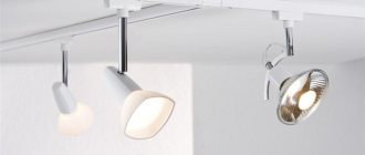
LED matrices are improving every year and recently manufacturers have developed a new type of matrices for spotlights that can be connected directly to a 220 V AC power supply.
Easy to connect, no need for an expensive driver, a number of matrices are available with power from 10 to 50 W. I decided to study the advantages and disadvantages of this type of LED matrices in practice.
About five years ago we had to repair two LED spotlights. In one of them the matrix and driver burned out, and in the second only the driver. One of the two was repaired. The second one, with a burnt-out matrix and driver, has been collecting dust on the shelf ever since. I decided to repair it using a modern LED matrix.
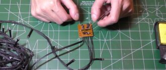
I bought two RoHS F4054 matrices with a power of 10 W for two dollars on Aliexpress, one in reserve, you never know what will happen during testing. By the way, the numbers in the markings after the letter F indicate the width and length of the matrix in millimeters. The purchased matrix had a size of 40×50 mm.
Operating principle and diagram
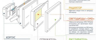
The LED spotlight (LED) includes the following components:
- LEDs (provide glow);
- drivers (control the operation of the device);
- frame;
- light diffuser (allows you to increase the efficiency of the lamp);
- lenses (control the shape, color and some other characteristics of the light flow).
The spotlight operates thanks to the coordinated actions of several of its components, including optics, power supply, drivers and heat sinks. The inside of the case contains light diodes, as well as small electronic components. The power supply supplies voltage to the LEDs, where the current is transformed into light output. Thanks to these actions, the device glows.
The figure below shows a standard electrical circuit for an electronic spotlight driver.
As for the operating principle of the driver, it does not differ on different spotlights. Power from the mains is supplied to the driver input, bypassing fuse F1. Next, filtering occurs using LC elements and rectification using a diode bridge. Smoothing is carried out by an electrolytic capacitor (C13). DC voltage (280 V) is generated at the capacitor terminals.
From the electrolytic capacitor, the voltage is directed through current-limiting resistors to the zener diode (D12) and pin No. 6 of the described microcircuit. The zener diode is responsible for the 9-volt power supply to the microcircuit, which is the main factor ensuring the functioning of the driver. From capacitor C13, current flows through the transformer winding (T1.1) through the lead part of the field-effect transistor (Q1).
Note! The amount of current flowing through the light diodes depends on the resistance parameters of the resistors on the microcircuit.
Continuity of individual LEDs
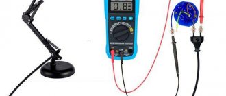
This type of test is one of the simplest and is done using a multimeter. A standard LED has two long contacts - an anode and a cathode. The cathode leg is slightly longer, and when viewed against the light, its electrode inside the housing is larger. In order to ring the LED, you must perform the following steps:
- move the switch to the Hfe position (this is the transistor test mode);
- find the connector on the panel marked PNP and NPN;
- The anode is inserted into slot C of the PNP zone, and the cathode is inserted into slot E of the NPN zone.
These pins are the positive and negative electrodes and cause the LED to glow. If this does not happen, then either the polarity is reversed (the diode leads must be swapped), or the element is faulty. Before checking an LED with a multimeter, it is recommended to determine where its anode and cathode are.
Since multimeters have different designs and characteristics, there are several types of sockets for testing transistors.
Read also: How to find out the expiration date of a gas cylinder
Despite the differences, they all have the required slots.
Signs of a spotlight malfunction
The most common signs of a malfunctioning spotlight:
- the lamp does not light up, although the power is turned on;
- the light diode flickers;
- the glow is too dim, as the lamp burns weakly - not at full power;
- the shade of the light flux has become unnatural.
Other signs may also be present, including physical damage to the structure of the case, deformation of the diode, burnt out electrical wiring.
When can a device be repaired - expediency
The price of a quality spotlight is usually high. An experienced technician can disassemble almost any device, even a sealed one, which means it can be repaired. But we must take into account the cost of spare parts and the complexity of repairs.
The power supply most often fails, because only the LED crystals themselves are durable in the device. Finding the perfect block is not easy
Here it is important to take into account all parameters for power and voltage, otherwise there will be consequences for the remaining elements of the device. If the power supply costs more than the spotlight itself, repairs are not advisable. In other cases, you can try to repair the spotlight, having previously calculated the costs
In other cases, you can try to repair the spotlight, having previously calculated the costs.
In order for lighting equipment to work properly for many years, it is better not to use it for too long. It’s not worth leaving it on all night, which wastes a lot of potential. During installation, you must carefully check all connections for bad contacts - this will cause voltage surges. These rules will help make the work of the spotlight long and uninterrupted.
Causes of failure
Possible reasons for the spotlight not working properly:
- Unstable electrical network (voltage drops beyond the operating current);
- short circuit of a phase to the device body or to neutral;
- incorrect connection;
- overvoltage;
- use of overcurrents.
In the event of these violations, the board on which drivers, voltage and current converters are installed, supplying power to the matrix crystals, may fail. Damage to 3 to 5 crystals in a floodlight matrix is allowed. If the number of faulty crystals is greater, the spotlight will not be able to operate with a sufficient degree of functionality and the matrix will need to be replaced.
Main conclusions
It is not difficult to check LEDs with a multimeter if you understand the principle of their operation. The main task is to prepare the conditions, modify the probes or make special contacts. The correct polarity plays an important role, changing which will not allow even a working element to glow. The process does not take much time; preparation, dismantling or disassembling of devices takes longer. The general principle is to apply the appropriate voltage to the problem element, from which it should light up if it is in working condition. If the glow is not observed even when the polarity is changed, it means that the LED (or section of the strip) is faulty and must be replaced.
Diagnostics
First of all, it is necessary to determine the cause of the LED spotlight malfunction. As an example, let's talk about checking the performance of a rectangular Volpe spotlight with a matrix including 9 diodes. The total power of the lamp is 10 W. The luminous flux is 750 lm.
The check is carried out in the following order:
- Inspect the wiring for physical integrity. Check for breaks, burnt insulation, or kinks in the cable. The purpose is to ensure that there are no breaks in the conductor.
- Check the device body, as well as the LED matrix for mechanical damage (deformation, chips, cracks).
- The next task is to check the input voltage by opening the back panel of the case. The input voltage should be 220V (AC). If there is no voltage, the cause of the breakdown is not in the lamp, but in the electrical circuit. Measurements are carried out with a standard multimeter. The output voltage is 12 V (DC).
- If there is no output voltage, the breakdown is looked for on the converter board. Inspect the contacts for oxidation, look for cracks in the tin coating in areas of soldering or burnt-out elements.
- If the above verification methods do not produce results, test the performance of the matrix.
What to do if the power of the LED module is unknown
There are situations when there is an LED chip, but its power, current and voltage are unknown. Accordingly, it is difficult to buy it, and if it is working, it is not clear how to choose an adapter.
This was a big problem for me until I figured it out. I am sharing with you how to determine from the appearance of an LED assembly what voltage, power and current it is.
For example, we have a spotlight with the following LED assembly:
9 diodes. 10 W, 300 mA. In fact - 9 W, but this is within the margin of error.
The fact is that LED matrixes of floodlights use 1 W diodes. The current of such diodes is 300...330 mA. Naturally, all this is approximately, within the margin of error, but in practice it works accurately.
In this matrix, 9 diodes are connected in series, they have one current (300 mA), and a voltage of 3 Volts. As a result, the total voltage is 3x9 = 27 Volts. For such matrices, you need a driver with a current of 300 mA, a voltage of approximately 27V (usually from 20 to 36V). The power of one such diode, as I said, is about 9 W, but for marketing purposes this spotlight will have a power of 10 W.
The 10 W example is a bit atypical due to the special arrangement of the LEDs.
Another example, more typical:
LED assembly for 20 W floodlight
You already guessed that two horizontal rows of dots of 10 pieces each are LEDs. One strip is, offhand, 30 Volts, current 300 mA. Two strips connected in parallel - voltage 30 V, current twice as much, 600 mA.
A couple more examples:
5 rows (zig-zag) of 10 LEDs.
Total - 50 W, current 300x5 = 1500 mA.
Matrix 7 rows of 10 LEDs
Total - 70 W, 300x7 = 2100 mA.
I think there is no point in continuing, everything is already clear.
The situation is slightly different with LED modules based on discrete diodes. According to my calculations, one diode there usually has a power of 0.5 W. Here is an example of a GT50390 matrix installed in a 50 W floodlight:
LED floodlight Navigator, 50 W. LED module GT50390 – 90 discrete diodes
If, according to my assumptions, the power of such diodes is 0.5 W, then the power of the entire module should be 45 W. Its circuit will be the same, 9 lines of 10 diodes each with a total voltage of about 30 V. The operating current of one diode is 150...170 mA, the total current of the module is 1350...1500.
Anyone who has other thoughts on this matter is welcome to comment!
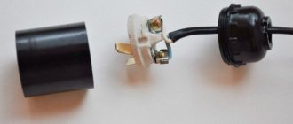
Replacing parts
Eliminating broken wiring does not require special qualifications from a home technician. It is much more difficult to find and fix a breakdown on a printed circuit board, driver, voltage converter or matrix. You can’t do this without special knowledge. You will also need the ability to work with diagnostic instruments and a soldering iron.
The following parts may be subject to repair or replacement:
- limiting capacitor;
- power unit;
- driver;
- matrix.
Current limiting capacitor
This component causes a malfunction when the spotlight lamp burns unevenly, constantly flickering. This problem is usually associated with the fact that manufacturers, in an effort to save money, install a current limiter that does not match the characteristics of the driver.
power unit
A common cause of malfunctioning of the spotlight is a breakdown of the power supply. In such a situation, you can purchase a new power supply or pick up this part from another device (for example, from a printer). If you decide to buy a new unit, it is recommended to take it with you to the store, since its technical characteristics are indicated on the case. To get the block, you first need to disassemble the spotlight.
Driver
Low-power models often lack a power supply. In such cases, an LED driver is used instead of a block. Since the diode is not able to receive power directly from the network (an alternating current other than the mains is needed), the driver is used. The device operates based on operating temperature and time, changing the output current to the LED.
To replace the driver, you should disassemble the spotlight to set the technical parameters of the driver, and then contact the store. Just as in the case of a power supply, you can select a suitable driver from another device.
Matrix
The most common cause of spotlight malfunction is excessive heating of the matrix, which leads to blown fuses. The spotlight is disassembled, after which the damaged matrix is taken out. To do this, unscrew the four screws and solder off the conductive parts. Next, apply a layer of thermal paste to the LED and solder the conductive parts back. The operation is completed by screwing the matrix into place.
In some cases, the wiring in the matrix goes through the holes in the substrate. It acts as a matrix radiator. In the transition areas, the wires must be covered with an insulating layer (primarily we are talking about the positive wire). This will avoid a short circuit to the device body.
Advice! Before replacing the matrix, you should clean the substrate and the area where it will be installed. It is recommended to treat these areas with a heat-conducting compound.
The shape of the matrix must not be disturbed. It is recommended to use only “original” screws so as not to damage the design. Also, do not forget about the polarity: the red wire is positive, the black or blue wire is negative, the green-yellow wire is directed to the body.
If at least 2-3 burnt-out diodes are detected, you should not wait for the matrix to burn out completely. In any case, the device is no longer able to function normally, as a result of which the drivers and voltage converter will soon fail.
Note! If the matrix does not work with a filled compound element, it cannot be restored.
Voltage converter circuit board
If, when checking the board, obvious signs of burnt-out elements are found, the device will need to be repaired. The figure below shows a converter circuit for a spotlight.
Before replacing non-functioning parts, you should ring the LEDs. First, one of the board legs is unsoldered, since ringing the soldered elements will not give the correct result. If necessary, burnt out parts are replaced with new ones.
Low power floodlight repair
As an example, let's look at the repair of the SDO01-10 floodlight. Device power - 10 W. An external inspection shows peeling of the protective coating on one of the floodlights. There are also dark spots on the light-emitting surface of the matrix.
Repairing a matrix with a damaged LED emitter is possible, but such a part is not cheap. The cost reaches 40-50% of the price of the entire spotlight. In addition, purchasing a new matrix presents another difficulty - most often there are no markings on the LEDs. As a result, it is not easy to determine the type of emitter.
To simplify the task, we install the spotlight driver from the burnt-out matrix to a lamp with a working matrix. On the old driver, the protective resistor burned out (its value is 1 Ohm), which indicates a breakdown of the diode in the diode bridge at the transition from the key resistor to the control resistor. However, replacing the driver did not restore the functionality of the spotlight.
After further testing, a break in the optical feedback pair was detected. Replacing the pair gave results - the lamp started working.
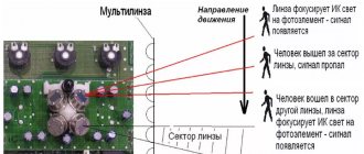
Infrared
As we acquire consumer electronic devices, each of us gradually becomes the owner of a whole battery of remote controls. As long as the equipment obediently responds to your commands, there is nothing to worry about.
But it is quite possible that desperate attempts to change the channel or turn down the brightness of the chandelier do not lead to any result. In such cases, first check the status of the infrared LED, through which the remote control transmits your requirements to the main device.
Read also: Do-it-yourself stationary electric planer
There are several ways to check the IR LED in a remote control or other device. Let's start with the simplest:
Direct the diode radiation into the lens of a digital camera. Not only a camera will do, but also a phone, laptop, video recorder, web camera, etc. IR radiation is absolutely invisible to the human eye, but electronic “eyes” register it very well. If the LED is performing its functions properly, purple flashes will be observed on the matrix.
If you don’t have a gadget that can remove it, the suspected LED can be dismantled by replacing it with a super-bright or SMD-type LED. Just make sure that the operating voltage of both elements is the same.
If the test LED emits visible light when pressing buttons on the remote control (most likely, it will be dim), then the IR LED has already served its purpose.
A more complicated method, but it does not require a camera or soldering. You can use an infrared photodiode. When infrared radiation hits the sensor of this element, a potential difference is formed at its terminals.
To test any IR LED, its radiation must be directed to the sensitive area of a photodiode previously connected to the open input of the oscilloscope.
If pulse curves appear on the device screen, the LED under test is in working condition. If you observe complete calm, then it’s time to buy a new IR LED.
Repair of a powerful spotlight
The subject of consideration is the model of a powerful spotlight SDO01-30. Devices of this type are used for lighting large rooms (for example, industrial purposes).
First, we remove the back panel from the spotlight and visually inspect the condition of the radio components on the printed circuit board. We pay attention to elements that look suspicious (carbon deposits, deformations, etc.).
Next, we inspect the printed circuit board (pulling it out of the spotlight) from the semiconductor side. An inspection revealed the presence of a pair of burnt-out resistors: R8 (2 ohms) and R22 (1 ohms). Resistors with low resistance most often burn out due to the high current passing through them in the event of a breakdown of semiconductors or capacitors.
Next to the resistors is a field-effect transistor SFV4N65F. The ringing determined its malfunction. Since the spotlight circuit was not available, we find out the values of the resistors that burned out by disassembling a working lamp of the same model.
We unsolder the failed resistors, as well as the transistor. We replace them with new parts.
Useful tips
Some useful tips for repairing LED floodlights:
- When replacing the matrix, be sure to pay attention to the polarity.
- Be sure to remove the hardened heat-conducting paste under the matrix.
- The surface should be degreased with alcohol.
- When soldering, you do not need to overheat the surface. Soldering time is up to 2 seconds. If the matrix is overheated, the crystals will be destroyed or their new characteristics will not allow the spotlight to function normally.
- To repair a high-power spotlight, the knowledge used in repairing low-power lamps is sufficient. There are no special differences between devices of different power.
- If a matrix with a large number of diodes is not filled with a compound solution, the non-working diode will need to be replaced. To perform this operation, a micro-soldering iron is required. You need to work carefully so as not to overheat the crystals.
- If it is impossible to see the values on the burnt-out resistances, you cannot do without the instructions for the spotlight. It must contain the relevant data.
Anyone can fix a spotlight. However, to perform repair work, at least basic knowledge of electrical engineering is required, as well as skills in using a soldering iron and a multimeter. You also need the ability to read diagrams to understand the design of the spotlight.