The quantity characterizing the amount of energy losses that occur when current flows through its source is defined as the internal resistance of the current source. Like regular resistance, it has a unit of measurement equal to 1 ohm. The current, moving through the source, loses part of its energy, which turns into heat, just like at any load resistance. This means that the voltage value at the source terminals depends on the current value, and not on the EMF.
Dependence of the voltage between its terminals on the source current
If we consider a closed electrical circuit that includes a current source (battery, accumulator or generator) and a load R, then the current flows inside the source. The internal resistance of the source, denoted by the letter r, prevents it.
For a generator, r is the internal resistance of the stator windings; for a battery, it is the resistance of the electrolyte.
Measurement of phase-zero loop resistance
A “phase-zero” loop is an alternating current electrical circuit that can result from a short circuit between the wires: “phase” and “zero” or “phase” and “phase”. Destruction of insulation, mechanical damage or accidental connection of exposed cable sections to each other can cause this. In installations with a solidly grounded neutral, the neutral conductor is physically connected to the neutral of the transformer; it is connected to the ground loop. When there is a short circuit to the housing or the phases are connected to each other, a circuit (loop) is formed.
The main task of the measurements taken is to find out what the magnitude of the current through the loop will be during a short circuit. This is mandatory for the calculation and selection of protective equipment. A good result will be a low loop resistance, then the current Ik.c. will be the greatest. Its value determines how quickly the protective circuit breaker will operate.
The less time spent disconnecting a damaged or shorted circuit, the greater the chance of preventing a cable fire. If a person gets an electric shock due to touch or short circuit, automatic voltage relief will save his life.
Enterprises annually carry out a set of measurements of protective grounding and phase-zero loop resistance. If the results are unsatisfactory, a number of measures are taken:
- sections of the wire that do not meet the requirements for cross-sectional diameter are replaced;
- bolted connections are twisted with the obligatory installation of mortise washers;
- the protective grounding contours are opened and inspected for the integrity of welded joints and the condition of the grounding elements;
- if necessary, additional elements are added to the protective grounding loop;
- serial connection of device housings to a common ground bus is eliminated.
After completing a set of measures, measurements are repeated.
Checking the resistance of the phase-zero loop
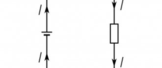
Current, current strength in a circuit.
Let's analyze what will happen if charged particles, for example, electrons, come under the influence of an electric field. Consider a conductor to which a certain voltage :
From the direction of the electric field strength (E), we can conclude that \phi_1 > \phi_2 (the intensity vector is always directed towards decreasing potential). A force begins to act on each electron:
F = Ee
where e is the electron charge.
And since the electron is a negatively charged particle, the force vector will be directed in the direction opposite to the direction of the field strength vector. Thus, under the influence of force, particles, along with chaotic motion, also acquire directional motion (velocity vector V in the figure). an electric current arises .
As a result, we find that current is the ordered movement of charged particles under the influence of an electric field.
The important point is that current is assumed to flow from a point with a more positive potential to a point with a more negative potential, even though the electron is moving in the opposite direction.
Not only electrons can act as charge carriers. For example, in electrolytes and ionized gases, the flow of current is primarily associated with the movement of ions, which are positively charged particles. Accordingly, the direction of the force vector acting on them (and at the same time the velocity vector) will coincide with the direction of the vector E. And in this case, no contradiction will arise, because the current will flow exactly in the direction in which the particles are moving.
In order to estimate the current in a circuit, there is such a quantity as current strength. So, current strength (I) is a quantity that characterizes the speed of movement of an electric charge at a point. The unit of current is Ampere. The current strength in a conductor is 1 Ampere if a charge of 1 Coulomb passes through the cross-section of the conductor in 1 second.
We have already looked at the concepts of current and voltage, now let’s figure out how these quantities could be related. And for this we have to understand what the conductor resistance is.
Finding internal resistance
Current resistance: formula
It can be found in two ways: calculated or measured. The first path is taken when working with electrical circuits, the second is chosen when working with real devices.
A simple calculation is made using the Ohm's Law formula for a section of a complete circuit:
I = ε / (r + R).
To find out the current strength, you need to divide the EMF voltage by the sum of the resistances.
Expressing r from here, we get the formula for calculating it:
r = (ε / I) – R,
Where:
- r – internal resistance of the source;
- ε – source emf;
- I – current strength in the complete circuit;
- R is the resistance in the complete circuit.
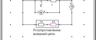
The complex of measurements of this parameter for this device does not imply direct measurements. The voltages across the load resistance are tested in two current modes: no-load and short-circuit.
Since not any source can withstand even a short-term short circuit, a measurement method without calculations is taken.
The circuit includes an external load resistance in the form of a trimming resistor Rн. The value is set at which the voltage drop across the resistor would be equal to 1/2 U no-load. Then Rн measured by an ohmmeter will correspond to the internal resistance of the source.
Internal resistance of the current source
Definition and formula of EMF
Definition
A scalar physical quantity that is equal to the work of external forces to move a unit positive charge is called electromotive force (EMF)
, acting in a circuit or section of a circuit.
EMF is denoted by $\varepsilon$ . Mathematically, we write the definition of EMF as: $$\varepsilon=\frac{A}{q}(1)$$
where A is the work of external forces, q is the charge on which the work is performed.
The electromotive force of the source is numerically equal to the potential difference at the ends of the element if it is open, which makes it possible to measure the EMF by voltage.
The EMF that acts in a closed circuit can be defined as the circulation of the tension vector of external forces:
$$\varepsilon=\oint_{L} \bar{E}^{*} d \bar{l}(2)$$
where $\bar{E}^{*}$ is the field strength of external forces. If the field strength of external forces is not zero only in part of the circuit, for example, on segment 1-2, then integration in expression (2) can be carried out only over this section. Accordingly, the EMF acting on circuit section 1-2 is defined as:
$$\varepsilon=\int_{1}^{2} \bar{E}^{*} d \bar{l}(3)$$
Formula (2) gives the most general definition of EMF, which can be used for any cases.
Reactive internal resistance
Impedance
In addition to galvanic and electrolytic two-terminal networks, there are power supplies whose circuits include reactive elements. When determining their internal resistance, the complex amplitude method is used. It involves using the complex resistances of the elements included in the circuit in calculations. The values of currents and voltages are replaced by the values of their complex amplitudes. The calculation algorithm itself is the same as when calculating active resistance.
The process of measuring r-reactance is slightly different from measuring the active component of resistance. The methods depend on what parameters of this complex function need to be learned: individual components or a complex number.
These parameters are affected by frequency, therefore, in order to obtain information about the internal reactive value r during testing, it is necessary to remove the frequency dependence. This is achieved by a set of measurements over the entire frequency range generated by such a two-terminal network.
Effective values
The arithmetic mean value of voltage and the rate of charge change over a period is zero, so it cannot be used to characterize the oscillatory process. The squares of these quantities, their average values are always positive.
The square of the average current value is equal to half the square of the amplitude value:
Is2 = Im2/2.
Is – average value. It is also called effective (another name is acting):
Is = Im/√2.
The square of the current is proportional to the amount of energy generated in the conductor: Q ~ Is2.
The effective value of the alternating current is equal to the direct current, at which the same amount of heat is generated during the time t = T. For the effective voltage value the formula is similar:
Us = Um/√2.
It is the effective values that are shown by measuring instruments.
High internal resistance
Piezoelectric sensors, condenser microphones, and other pulse sources have increased internal impedance. To effectively use such devices, you need to properly match the signal reading circuit. If coordination fails, losses are inevitable.
Important! Successful voltage matching is obtained when using a device with a higher input impedance than that of the signal source to pick up a signal. In the case of a high-impedance source, a buffer amplifier is used to read the signal.
Two-terminal network and its equivalent circuit
A two-terminal network is an electrical circuit containing two points of connection to other circuits. There are two types of electrical circuits:
- circuits containing a source of current or voltage;
- bipolar networks that are not sources.
The first are characterized by electrical parameters: current, voltage and impedance. To calculate the parameters of such two-terminal networks, real circuit elements are first replaced with ideal elements. The combination that results from such a replacement is called an equivalent circuit.
Attention! When working with complex electrical circuits, taking into account the fact that the device operates at the same frequency, it is permissible to convert serial and parallel branches to obtain a simple circuit available for calculating parameters.
The second type of two-terminal circuits can be characterized only by the value of internal resistance.
EMF source
An EMF source (ideal voltage source) is an element of an electrical circuit whose terminal voltage does not depend on the current flowing through it. EMF source m.b. specified either as a constant value or as a function of time or external control. An ideal EMF source has the following graphic designation on electrical diagrams: In practice, ideal EMF sources do not exist. Let's try to make sure of this: Let's write Ohm's law for the complete circuit: Note that when the external resistance is reduced to zero, we get an infinite increase in current strength, which is physically impossible. For this reason, the concept of a real voltage source is introduced. A real voltage source is an element of an electrical circuit with a resistance r on which an emf acts. Indicated by: Real voltage source m.b. presented as a series connection of an EMF source and resistor r:
// here you need to add about choosing the direction of the EMF //
The influence of internal resistance on the properties of a two-terminal network
The higher it is, the less power the source produces when a load is connected. The power in the load can be determined using the formula:
PR = E2/(r+R)2*R,
Where:
- E – EMF voltage;
- R – load resistance;
- r – active internal resistance of a two-terminal network.
The formula is applicable to two-terminal networks that do not release energy.
For your information. When the internal resistance of the two-terminal network approaches the load resistance, the power transfer reaches a maximum.
Source discharge capacity
The value depending on the strength of the discharge current is called the discharge capacity of the source. This is an electric charge that the source gives off during operation depending on the load current. This value can be considered constant conditionally. Thus, a starter battery with a discharge capacity C = 55 A*h will work for 10 hours at a discharge current of 5.5 A. When starting a cold or malfunctioning vehicle, the battery can be discharged in a few minutes.
In order to find the residual discharge capacity, charge-discharge cycles are performed. They are performed using load resistors. The discharge to the load resistance is carried out to the minimum permissible values of the electrolyte density. In this case, the operating time under load is measured. This is relevant during seasonal maintenance of batteries to identify self-discharge processes.
Car battery discharge capacity
The internal resistance of current sources is an important quantity. The methods used to reduce it are direct ways to increase the output power of the source, which means increasing the productivity of two-terminal networks. Correct measurement and calculation of the impedance of equivalent circuits allows us to bring the two-terminal network closer to the ideal source.
Parallel connection of capacitors
Regardless of the type of capacitor or the materials used to make it, it always consists of two main parts: plates. Their shape does not matter, but they may consist of a series of plates rolled into a roll.
For most types of capacitors, the plates are equal. The polarity of the current source connection is important for electrolytic devices.
The ability to accumulate and retain charges is characterized by a physical quantity – electrical capacity. It is defined as the ratio of the charge on the plates to the potential difference between them:
C = q/Δφ.
Designations:
- C – electrical capacitance, unit of measurement – farads (F);
- q – charge, measured in coulombs (C);
- Δφ – potential difference, measured in volts (V).
In practice, this quantity is more often called voltage:
Δφ = φ2 – φ1 = U.
The electrical capacity of the charge storage device depends on the size of the plates, the size of the gap between them, and the dielectric material. For a capacitor in the form of two plates, it looks like this:
C = (εε0S)/d.
Designations:
- ε – dielectric constant of the material located between the plates;
- ε0 – one of the physical constants (electrical constant);
- d – distance from one plate to another (dielectric thickness);
- S is their area.
When soldering in parallel, the voltage between the plates is the same. For a system of two elements:
Ugen = U1 = U2;
- Charges received:
q1 = C1U, q2 = C2U;
- Total charge:
qgen = q1 + q2;
- Then the total capacity:
Cgen = qgen/Ugen = (q1 + q2)/Ugen = q1/U1 + q2/U2 = C1 + C2.
When connected in parallel, the system capacitance is found as the sum of the capacitances of the individual charge storage devices.
Capacitors have one more characteristic: the voltage for which they are designed. It depends on the properties of the dielectric and its thickness.
It is possible to connect capacitors with different capacities and different operating voltages in parallel. The performance of the battery is determined by the element with the lowest voltage.