POWER DELIVERED IN THE EXTERNAL CIRCUIT
. (2)
From formula (2) it is clear that with a short circuit (R®0) and with R® this power is zero. For all other finite values of R, the power P1> 0. Consequently, the function P1 has a maximum. The value of R0 corresponding to the maximum power can be obtained by differentiating P1 with respect to R and equating the first derivative to zero:
. (3)
From formula (3), taking into account the fact that R and r are always positive, and E? 0, after simple algebraic transformations we get:
R0 = r. (4)
Consequently, the power released in the external circuit reaches its greatest value when the resistance of the external circuit is equal to the internal resistance of the current source.
In this case, the current strength in the circuit (5)
equal to half the short circuit current. In this case, the power released in the external circuit reaches its maximum value equal to
. (6)
When the source is closed to an external resistance, then current flows inside the source and at the same time a certain amount of heat is released at the internal resistance of the source. The power expended to release this heat is equal to
. (7)
Consequently, the total power released in the entire circuit is determined by the formula
= I2(R+r) = IE (8)
Summary
- Power is a measure of how much work can be done in a given period of time.
- Mechanical power is usually measured (in America) in "horsepower".
- Electrical power is almost always measured in "watts" and can be calculated using the formula P = IE.
- Electrical power depends on both voltage and current simultaneously, and not separately.
- Horsepower and watt are just two different units to describe the same physical parameter, with 1 horsepower equal to 745.7 watts.
Original article:
- Power in Electric Circuits
EFFICIENCY
The EFFICIENCY OF the current source is equal to . (9)
From formula (8) it follows that
, (10)
those. P1 changes with the change in current in the circuit according to a parabolic law and takes zero values at I = 0 and at . The first value corresponds to an open circuit (R>> r), the second – to a short circuit (R<< r). Dependence of efficiency on the current strength in the circuit, taking into account formulas (8), (9), (10) will take the form
(11)
Thus, the efficiency reaches its highest value h =1 in the case of an open circuit (I = 0), and then decreases according to a linear law, becoming zero in the case of a short circuit.
Dependence of powers P1, Ptotal = EI and efficiency. current source and the current strength in the circuit are shown in Fig. 1.
Fig.1. I0 E/r
From the graphs it is clear that to obtain both useful power and efficiency. impossible. When the power released in the external section of the circuit P1 reaches its greatest value, efficiency. at this moment it is 50%.
What is power in electricity: simply about the complex
I remembered the epic about Ilya Muromets, when he applied all his power to the nightingale robber. The poor guy immediately started to see sparks coming out of his eyes, like the flames from the top picture on the incorrectly installed wiring.
In simple words: power in electricity is a power characteristic of energy, which is used to evaluate both the ability of generator sets to produce it and the capabilities of consumers and transport routes.
All these areas must be accurately assembled and adjusted to ensure safe operation. As soon as a malfunction occurs anywhere, an accident immediately develops in the entire circuit.
When it comes to home electrical equipment, you have to constantly strike a balance between:
- devices connected to the network;
- design of wires and cables;
- setting up protective devices.
Only a comprehensive solution to these three issues can ensure the safety of wiring and residents.
How to calculate electrical power at home
Formulas for calculating power in electricity allow you to perform a qualitative assessment of the safety of each of the above items.
They are not difficult to use. In previous articles I have already provided an electrician’s cheat sheet, where they are presented in a visual form for DC circuits.
They are completely valid for the active component of alternating current power that does useful work. By the way, besides it there is also a useless one - reactive, associated with energy loss. The second section is devoted to its description.
It is convenient to do such calculations using an online calculator. It eliminates routine mathematical calculations and arithmetic errors.
With any of the methods, to calculate active power, you need to know two of three electrical quantities:
- current strength I;
- applied voltage U;
- circuit section resistance R.
How to measure electrical power at home
There is another possibility for estimating active power: its measurement in an operating circuit using special devices: wattmeters.
An industrial laboratory wattmeter can provide accurate measurements. It is manufactured both as a device operating on analog signals and using digital technologies.
In household wiring, precise calculations are not needed. Various types of simpler wattmeters are produced for it.
Devices that can be plugged into an outlet and connected to a power cord from the consumer are popular, turn them on and immediately take readings on the display in watts.
They are called that: wattmeter socket. They measure pure active AC power.
Such devices relieve the electrician from performing complex operations under voltage when it is necessary to measure:
- effective voltage;
- current strength;
- phase shift angle between current and voltage vectors.
Then all the data additionally needs to be entered into the formula for calculating power by current and voltage, and calculations must be made using it.
This method can be simplified by carefully observing the electrical meter of a rotating disk induction system. It calculates the work done: the power consumed over a certain time.
However, the rotation speed of the disk precisely characterizes the amount of consumption. You just need to count how many times it turns around in a minute and convert it to watts according to the plate located on the case.
METHOD AND PROCEDURE OF MEASUREMENTS
Rice. 2.
Assemble the circuit shown in Fig. on the screen. 2. To do this, first click the left mouse button above the emf button. at the bottom of the screen. Move the mouse marker to the working part of the screen where the dots are located. Click the left mouse button in the working part of the screen where the emf source will be located.
Next, place a resistor in series with the source, representing its internal resistance (by first pressing the button at the bottom of the screen) and an ammeter (the button is in the same place). Then arrange the load resistors and voltmeter in the same way, measuring the voltage across the load.
Connect the connecting wires. To do this, click the wire button at the bottom of the screen, and then move the mouse marker to the working area of the circuit. Click with the left mouse button in the areas of the working area of the screen where the connecting wires should be located.
4. Set parameter values for each element. To do this, left-click on the arrow button. Then click on this element. Move the mouse marker to the slider of the regulator that appears, click on the left mouse button and, holding it down, change the parameter value and set the numerical value indicated in Table 1 for your option.
Table 1. Initial parameters of the electrical circuit
| Number option | 1 | 2 | 3 | 4 | 5 | 6 | 7 | 8 |
| E, B | 10,0 | 9,5 | 9,0 | 8,5 | 8,0 | 8,5 | 9,0 | 9,5 |
| r, Ohm | 4,8 | 5,7 | 6,6 | 7,5 | 6,4 | 7,3 | 8,2 | 9,1 |
5. Set the external circuit resistance to 2 Ohms, press the “Count” button and write down the readings of electrical measuring instruments in the corresponding lines of Table 2.
6. Use the regulator slider to consistently increase the resistance of the external circuit by 0.5 Ohms from 2 Ohms to 20 Ohms and, pressing the “Count” button, record the readings of electrical measuring instruments in Table 2.
7. Calculate using formulas (2), (7), (8), (9) P1, P2, Ptot and h for each pair of voltmeter and ammeter readings and write the calculated values in Table 2.
8. Construct on one sheet of graph paper the dependence graphs P1 = f(R), P2 = f(R), Ptot=f(R), h = f (R) and U = f(R).
9. Calculate the measurement errors and draw conclusions based on the results of the experiments.
Table 2. Results of measurements and calculations
| R, Ohm | 2,0 | 2,5 | 3,0 | 20 | |
| U, V | |||||
| I, A | |||||
| P1, W | |||||
| P2, VT | |||||
| Pfull, VT | |||||
| h |
Why do you need to know internal resistance?
At first glance, it may seem that the presence of internal resistance is interesting only from a theoretical point of view. In fact, in some situations, knowing what it equals can be vital.
One such situation is determining the health of a car battery. Its internal resistance is not constant. It changes under the influence of various factors and affects the voltage at the terminals. To be confident in the performance of the equipment, you need not only to be able to find its internal resistance, but also to know what its value corresponds to the norm.
The internal resistance of the power supply can be influenced by the following factors:
- Temperature conditions. The colder it is, the slower the rate of chemical processes in the battery. This leads to an increase in internal resistance and a gradual decrease in voltage at the terminals.
- Battery life. New devices have minimal internal resistance. Gradually it begins to grow. This is due to the fact that an irreversible chemical process occurs in the battery. In some cases it is relatively slow, and in others it can be quite noticeable. The latter, for example, applies to lead-acid batteries.
- Battery capacity.
- Sometimes the device may be subject to mechanical stress, which can cause internal breaks.
- Amount of electrolyte used.
- The current produced by the battery depends on the load on the circuit. Depending on it, the resistance changes.
The influence of a large number of factors leads to the fact that different values of internal resistance can be considered normal. However, its standard increase per year is considered to be 5%. If this norm is exceeded, it means that you need to pay special attention to the health of the battery.
When analyzing, it is worth taking into account not only those values that are indicated in the technical documentation. It is also necessary to take into account how intensively the resistance changes over time. This will give more accurate information about the health of the battery and help you understand what needs to be achieved to ensure the functionality of the equipment.
One of the simplest ways to measure internal resistance can be demonstrated with the following example. Its use is possible provided that the emf of the battery is known.
EMF (ℰ, unit of measurement - volts, V) is the electromotive force of the power source, equal to the ratio of the work of external forces to move a charge from the negative pole of the source to the positive pole to the value of this charge: ℰ = A/q. If there is no load connected to the power source, then the EMF is equal in value to the voltage at its terminals.
The situation will be considered when the EMF is 1.5 V. An electrical circuit is created in which the battery outputs are connected to a light bulb. The voltage drop across it and the current passing through the circuit are measured. They are respectively equal to 1.2 V and 0.3 A.
The figures given here are approximate. When measuring, the technician can select a different type of electrical load if he deems it necessary.
Using Ohm's law, you can determine the resistance of a light bulb:
R = U / I = 1.2 / 0.3 = 4 ohms.
In this formula, the letter R denotes the total resistance of the circuit. It can be expressed as the sum of r + R, where r is the internal resistance and R is the normal resistance.
Then: R + r = ℰ / I
From this formula, r = ℰ / I − R = 1.5 / 0.3 − 4 = 1 Ohm is determined.
An important condition for finding the value of r is knowledge of the magnitude of the electromotive force. This characteristic has a maximum value for new and well-charged batteries. Those that have been in use for a long time may have a significantly lower EMF due to discharge and wear, which is often associated with irreversible chemical processes in the battery.
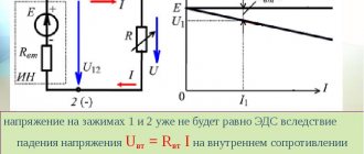
To determine ℰ, you must disconnect any load from the power supply terminals and connect a voltmeter or multimeter in voltage measurement mode. The device will show the EMF value. Why is easy to understand. According to Ohm's law for a complete circuit:
I = ℰ / (R + r),
since the voltmeter has a resistance R→∞, then the current I≈0. Therefore, the voltage at the terminals is equal to the emf:
U = I·R = ℰ – I·r = ℰ.
It should also be mentioned that only an ideal voltage generator has zero internal resistance “r”. There are also elements with high internal resistance - these are different sensors, signal sources, and only an ideal current source has r=∞. In addition, there are two-terminal networks with a negative r value; it can be obtained in feedback circuits and in elements with negative differential resistance. The calculations are applicable not only for a battery, but also for any other current source, for example, a galvanic battery, a two-terminal network, a phase-zero loop. This knowledge can be used to match source and load, reduce high voltages and minimize noise.
Questions and tasks for self-control
- Write the Joule-Lenz law in integral and differential forms.
- What is short circuit current?
- What is gross power?
- How is efficiency calculated? current source?
- Prove that the greatest useful power is released when the external and internal resistances of the circuit are equal.
- Is it true that the power released in the internal part of the circuit is constant for a given source?
- A voltmeter was connected to the flashlight battery terminals, which showed 3.5 V.
- Then the voltmeter was disconnected and a lamp was connected in its place, on the base of which it was written: P = 30 W, U = 3.5 V. The lamp did not burn.
- Explain the phenomenon.
- When the battery is alternately shorted to resistances R1 and R2, an equal amount of heat is released in them at the same time. Determine the internal resistance of the battery.
What is power and how to measure it?
Power is a measure of how much work can be done in a given period of time. Work is usually defined as lifting a load against gravity. The larger the mass, and/or the higher it rises, the more work must be done. Power is a measure of how quickly a standard amount of work is performed.
For American automobiles, engine power is measured in units called "horsepower," which were originally invented by steam engine manufacturers to quantify the performance of their cars in terms of the most common power source of their time: horses. One horsepower is defined in imperial units as 550 ft·lbs of work per second. A car's engine power will not indicate the height of a hill it can climb or how much mass it can pull, but it will indicate how fast it can climb a certain hill or pull a certain mass.
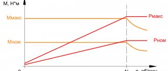
The power of a mechanical engine depends on both the speed of the engine and its torque at the output shaft. The speed of the motor output shaft is measured in revolutions per minute or rpm (RPM). Torque is the amount of rotational force produced by an engine and is usually measured in newton meters (or pound-feet). Neither speed nor torque alone are a measure of engine power.
A 100 horsepower diesel tractor engine rotates the shaft relatively slowly, but provides a lot of torque. A 100 horsepower motorcycle engine turns the shaft very quickly, but provides relatively little torque. Both will produce 100 horsepower, but at different speeds and different torque. The equation for shaft power is simple:
\[\text{Horsepower} = \frac{2 \pi ST}{33,000}\]
Where
- S – shaft rotation speed in rpm;
- T is the torque in lb-ft.
Note that on the right side of the equation there are only two variables, S and T. All other terms on this side are constant: 2, π and 33,000 are constants (they do not change their value). Horsepower changes only with changes in speed and torque, nothing else. We can rewrite the equation to show this relationship:
Horsepower ∝ ST
∝ – means “proportional”
Since the unit of "horsepower" is not exactly the same as the speed in rpm times the torque in lb-ft, we cannot say that power equals ST. However, they are proportional to each other. As the mathematical product ST changes, the power value will change in the same proportion.
Electrical power: DC circuit
The previously mentioned formulas are shown without correction factors. They are used to calculate a circuit connected to a direct current source. Using an ordinary device - a multimeter, with the switch in the correct position, the resistance of the load connected to the network is set.
With its help, the load resistance is set. Source hammer-shop.ru
Electrical power and inactive power
Equipment certificates contain active load - power factor, which is an important characteristic. It shows how efficiently a household appliance consumes electricity.
Fig.8
This is a number from −1 to 1, it is never equal to one. This coefficient depends on the type of load: C, L or R. The first 2 negatively affect PF = cos φ of the system. If its parameter is large, the current consumed by the devices increases. Many power loads are inductive, causing the current to lag behind the voltage.
Inactive energy arises in electrical AC circuits of alternating current networks. It is calculated simply: the square root of the sum (Pa2 + Pr2). If the reactive load is zero, then the passive load is equal to the modulus |Pa|.
The presence of nonlinear current distortions in electrical networks is caused by non-compliance with the direction that occurs between U/I, since the energy has a pulsed nature. In nonlinear modes, the apparent current power (EP) increases. Such a load is inactive and consumes Pr and current distortion energy. The unit of measurement is the same as regular power W.
Electrical current through voltage and current
Since the potential difference calculated by the formula (F1-F2) determines the voltage (U), it is easy to conclude that the relationship established by Ohm’s law cannot be used. Electrical power (P) is also qualified by the current strength (I) on a specific section of the line. Final expression: P = U x I.
What is the load determined in terms of current and resistance?
Through a simple conversion, the electrical energy consumption is determined using the following formula: P = I2 x R. This shows the dependence of the power on the nominal value of the resistor connected to the line of the network element. For a complete circuit, the source resistance (internal) and the conductance of the connection point are indicated.
Definition and formula of useful power
Definition Power is a physical quantity that is used as the main characteristic of any device that is used to perform work. Useful power can be used to complete the task at hand.
The ratio of work ($\Delta A$) to the time period during which it was completed ($\Delta t$) is called the average power ($\left\langle P\right\rangle $) for this time:
\[\left\langle P\right\rangle =\frac{\Delta A}{\Delta t}\left(1\right).\]
Instantaneous power, or more often simply power, is the limit of relation (1) at $\Delta t\to 0$:
\[P={\mathop{\lim }_{\Delta t\to 0} \frac{\Delta A}{\Delta t}\ }=A'(t)\left(2\right).\]
Taking into account that:
\[\Delta A=\overline{F}\cdot \Delta \overline{r\ }\left(3\right),\]
where $\Delta \overline{r\ }$ is the movement of the body under the action of force $\overline{F}$, in expression (2) we have:
\[P={\mathop{\lim }_{\Delta t\to 0} \left(\frac{\overline{F}\cdot \Delta \overline{r\ }}{\Delta t}\right) \ }=\overline{F}{\mathop{\lim }_{\Delta t\to 0} \left(\frac{\Delta \overline{r\ }}{\Delta t}\right)=\ } \overline{F}\cdot \overline{v}\left(4\right),\]
where $\ \overline{v}-$ is the instantaneous speed.
Electrical power: AC circuit
For such lines, it is unacceptable to use formulas that determine instantaneous parameters, since the final indicator changes from a minimum value to a maximum value with the network frequency. A typical single-phase 220 V network is characterized by a 50 Hz sinusoidal signal. It is allowed to use the simple formula P = U x I when connecting devices with resistive parameters:
- Heating elements of washing machines;
- spirals of infrared heaters;
- incandescent light bulbs.
Using this formula, the load is set.
An example of calculating the power of electric current
In the end, you will be able to test your knowledge with 2 common examples.
Imagine that in the first problem you have a resistor R = 50 Ohm through which an electric current I = 0.3A flows. What electrical power is converted in this resistor?
You can find the solution by finding the appropriate formula and plugging in the given values into it. That is, we get: P = I2R = 0.32 * 50 = 4.5 W
In the second problem, a resistor R is given, the electrical resistance of which is 700 Ohms. The technical description states that the maximum power of this resistor is 10 W. How high can the voltage applied to this resistor be?
To solve this problem, we select the appropriate formula: P = U2/R, from where we find Umax = Pmax * R = 700 * 10 = 83.67 V.
This means that the maximum voltage can be 83.67 V. To be on the safe side, you should choose an electrical voltage well below this limit.
I wrote in more detail about how to find the power of an electric current in the article:
