Selection of current transformers
Current transformers are selected according to rated voltage, rated primary current and tested for electrodynamic and thermal resistance to short-circuit currents. A feature of the selection of current transformers is the selection according to the accuracy class and checking for the permissible load of the secondary circuit.
Accuracy classes of current transformers
- Current transformers for connecting meters for which cash payments are made must have an accuracy class 0,5.
- For technical accounting, it is allowed to use current transformers of accuracy class 1;
- To turn on indicating electrical measuring instruments - not lower than 3 ;
- For relay protection - class 10(P) .
To ensure that the current transformer error does not exceed the permissible value for a given accuracy class, the secondary load Z2 should not exceed the rated load Z2nom specified in the catalogs.
The inductive reactance of such circuits is small, so they take Z2p = r2p. The secondary load g2 consists of the resistance of the devices g prib, the connecting wires gpr and the contact resistance gk:
To determine the resistance of devices powered by current transformers, it is necessary to draw up a table - a list of electrical measuring instruments installed in a given connection.
The total resistance of devices, Ohm, is calculated based on the total power:
In 6-10 kV switchgear, transformers with /2nom = 5A are used; in switchgear 110 - 220 kV - 1 or 5 A. The resistance of the main contacts is 0.05 Ohm for two or three devices and 0.10 for more devices. The resistance of the wires is calculated by their cross-section and length. For aluminum wires, the minimum cross-section is 4 mm2; for copper - 2.5 mm2.
The estimated wire length depends on the connection diagram of the current transformer and the distance l from the transformer to the devices:
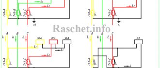
- when switching current transformers into an incomplete star;
- 21 - when all devices are turned on in one phase;
- l - when turning on current transformers in a full star.
In this case, the length l can be taken approximately for switchgear 6-10 kV:
- when installing devices in switchgear cabinets / = 4… 6 m;
- on the control panel /= 30…40 m;
- for RU 35 kV / = 45…60 m;
- for RU PO - 220 kV/ = 65...80 m.
If, with the accepted wire cross-section, the secondary resistance of the current transformer circuit turns out to be greater than ZHOU for a given accuracy class, then it is necessary to determine the required wire cross-section taking into account the permissible resistance of the secondary circuit:
where p is the resistivity.
The resulting cross-section is rounded up to a larger standard cross-section of control cables: 2.5; 4; 6; 10 mm2.
The conditions for selecting a current transformer are given in table. 7.5. Additionally, the following can be specified: KTN = 1t.tn/UR21nom - multiplicity of the dynamic resistance current of the current transformer; CT = /Т//|„ОМ – thermal resistance current multiplicity; /i„OM - rated current of the primary winding of the current transformer.
Used Books
- GOST 7746-2001 “Current transformers. General technical conditions".
- Rules for electrical installations, 7th ed.
- IEC 60044-1 INTERNATIONAL STANDARD. Instrument transformers — Part 1: Current transformers"
- M. Zicherman “Standards for instrument transformers. New requirements."
- Legostov V.V., Legostov V.V. “Measuring current transformers”, IZMERIENIE.RU No. 12 2'06
- Afanasyev V.V. "High-voltage CTs."
- GOST R 52736-2007 “Methods for calculating the thermal and dynamic effects of short circuit current.”
Seryakov Andrey Aleksandrovich, chief project engineer of the Technical Support Department of Engineering LLC
Selection of voltage transformers
Voltage transformers designed to power the voltage coils of measuring instruments and relays are installed on each section of the busbars. They are selected according to their design, design and connection diagram of the windings, rated voltage, accuracy class and secondary load.
Conditions for choosing voltage transformers
- design, connection diagram;
- compliance with the condition Uc.nom = U1nom (where Uc.nom is the rated voltage of the network to which the voltage transformer is connected, kV;
- U1.nom—rated voltage of the primary winding of the transformer, kV);
- accuracy class;
- compliance with condition S2 races
- S2 nom - rated power of the secondary circuit of the voltage transformer, ensuring its operation in a given accuracy class, V*A).
For single-phase transformers connected in a star, as U it is necessary to take the total power of all three phases, and for those connected according to an incomplete open triangle - twice the power of one transformer. In the selected accuracy class, if the load (secondary) exceeds the rated power, some of the devices are connected to an additionally installed voltage transformer. The secondary load of a VT is the power of the instruments and relays connected to the VT.
To simplify calculations, the design load can not be divided into phases, then
When determining the secondary load, the resistance of the connecting wires is not taken into account, since it is small. However, the PUE requires an assessment of the voltage loss, which in wires from transformers to meters should not exceed 0.5%, and in wires to panel measuring instruments - 3%. The wire cross-section selected for mechanical strength, as a rule, meets the requirements for voltage loss.
The choice of voltage transformer type is determined by its purpose. If metering meters receive power from the transformer voltage, then it is advisable to use two single-phase transformers of the NOM or NOL type at voltages of 6, 10, 35 kV, connected according to an open incomplete triangle.
Two single-phase VTs have more power than one three-phase one, and in terms of cost for voltages of 6 and 10 kV they are approximately equal. If, simultaneously with the measurement, it is necessary to monitor the insulation in 6-10 kV networks, then install three-phase three-winding five-rod voltage transformers of the NTMI series or a group of three single-phase transformers of the ZNOM or ZNUT series, if the power of the NTMI is insufficient.
When using three single-phase transformers connected in a star, the neutral point of the high voltage winding of the VT must be grounded for proper operation of the insulation monitoring devices
For voltages of 110 kV and above, NKF cascade transformers are used.
It's simple about counters
Good day, dear readers!
I haven't written anything for a long time. There's a reason for this. I'm doing renovations.
I wanted to make a few videos about installing wiring in an apartment, but I realized that it was not entirely interesting.
Therefore, today’s article is about electricity meters.
I threw out the pretentious and boring version of it and decided to write it as if I were telling it to an ordinary citizen, for example you, who knows nothing about meters.
Once upon a time, in my list of laboratory works there was a type of work: checking and adjusting accounting circuits. There was even a technique. And in electrical networks, the service for monitoring electricity metering was generally part of the laboratory, at least here in Ryazan...
Requirements for organizing commercial accounting
Requirements for installation locations of metering devices
Metering devices must be installed at the boundaries of the balance sheet of electric power facilities (power receiving devices) of adjacent entities of the retail market - consumers, network organizations that have a common boundary of balance sheet (hereinafter referred to as adjacent entities of the retail market). If there is no technical possibility of installing a metering device at the border of the balance sheet of electric power facilities (power receiving devices) of adjacent entities of the retail market, the meter must be installed in a place as close as possible to the border of the balance sheet where it is technically possible to install it.
If a metering device, including a collective (common house) metering device in an apartment building, is not located on the border of the balance sheet ownership of electric power facilities (power receiving devices) of adjacent entities of the retail market, then the volume of electrical energy consumption determined on the basis of the readings of such a metering device, in order to carry out settlements under the contract, it is subject to adjustment for the amount of electrical energy losses occurring in the network section from the border of the balance sheet ownership of electric power facilities (power receiving devices) to the installation site of the metering device (OPFRR clause 144).
Electricity metering devices (measuring systems) must be located in dry rooms that are easily accessible for maintenance , in a place that is sufficiently free and not cramped for work, with a temperature in winter not lower than 0°C. General industrial metering devices are not allowed to be installed in rooms where, due to production conditions, the temperature can often exceed +40°C, as well as in rooms with aggressive environments. It is allowed to place meters in unheated rooms and corridors of switchgears of power plants and substations, as well as in outdoor cabinets. If the devices are not intended for use in conditions of negative temperatures, they must be permanently insulated for the winter using insulating cabinets, hoods with heated air inside them, an electric lamp or a heating element to ensure a positive temperature inside the hood, but not higher than + 20°C (PUE clause 1.5.27).
Metering devices must be installed in cabinets, chambers of complete switchgears (KRU, KRUP), on panels, switchboards, in niches, on walls with a rigid structure. The height from the floor to the terminal box of the metering device must be within 0.8-1.7 m (PUE clause 1.5.29) (with the exception of technical solutions for installing the metering device at the connection point on a 0.4 kV overhead line support).
Designs and sizes of cabinets, niches, panels, etc. should provide convenient access to the terminals of meters and current transformers. In addition, it must be possible to conveniently replace the meter and install it with a slope of no more than 1° (PUE clause 1.5.31).
If there are several connections at the facility with separate electricity metering, the meter panels must contain inscriptions with the names of connections (PUE clause 1.5.38).
Requirements for metering devices
Selection of accuracy class:
- To meter electrical energy consumed by consumers (except for citizen consumers) with a maximum power of less than 670 kW, metering devices of the accuracy class must be used: for points of connection to power grid facilities with voltage from 0.4 kV to 35 kV - 1.0 and higher;
- for points of connection to power grid facilities with voltages from 110 kV and above – 0.5S and above. (OPFRR clause 138, clause 142).
Verification requirements:
- Each installed metering device must have seals with a metrological verification mark on the screws securing the casing of the metering device, and a seal from the network company on the clamping cover.
- The presence of a valid verification of the metering device is confirmed by the presence of a readable metrological verification seal and, as a rule, by providing a document - a passport form for the metering device or a verification certificate. The documents for the metering device must contain notes about the settings of the tariff schedule and local time.
Requirements for input devices and input communication devices
- It must be possible to conduct a complete visual inspection from stationary sites of input devices for overhead lines, cable lines, as well as input auxiliary electrical wiring of equipment to identify unmetered connections of power receiving devices. Places of possible unmetered connection must be isolated by sealing chambers, cells, cabinets, etc. (PTEEP clause 2.11.18).
- For loads up to 100 A inclusive, exclude the installation of disconnectors (switches) to the installation site of the metering unit. For the safe installation and replacement of metering devices in networks with voltages up to 1 kV, provision must be made for the installation of input circuit breakers (at a distance of no more than 10 m from the metering device) with the possibility of sealing (PUE clause 1.5.36).
- Installation of AVR, OPS and other automation equipment should be provided after the installation location of the electricity metering device (measuring complex).
Requirements for measuring voltage transformers
- Accuracy class – no worse than 0.5 (PUE clause 1.5.16).
- For three-phase input, use three-phase VTs or groups of three single-phase VTs.
- To protect the measuring circuits, it must be possible to seal the grilles and doors of the chambers where the fuses are installed (fuses are installed with an alarm for their operation (PUE clause 3.4.28) on the high and low voltage side of the VT, as well as the drive handles of the VT disconnectors. If sealing is not possible chambers, the TN leads are sealed (PTEEP clause 2.11.18).
- To ensure the safety of work carried out in the circuits of measuring instruments, relay protection devices and electrical automation, the secondary circuits (windings) of voltage measuring transformers must have permanent grounding (Occupational safety rules during the operation of electrical installations, clause 42.1).
- The secondary windings of the voltage transformer must be grounded by connecting the neutral point or one of the ends of the winding to a grounding device. Grounding of the secondary windings of the voltage transformer should be carried out, as a rule, at the terminal assembly closest to the voltage transformer or at the terminals of the voltage transformer (PUE clause 3.4.24).
- The presence of a valid verification is confirmed, as a rule, by providing original passports or TN verification certificates with verification protocols (PTEEP 2.11.11).
Requirements for measuring current transformers
- Accuracy class – no worse than 0.5 (PUE clause 1.5.16).
- When semi-indirectly switching on the metering device, it is necessary to install current transformers in all phases.
- The values of the rated secondary current must be linked to the rated currents of the metering devices.
- Current transformers used to connect meters at voltages up to 0.4 kV must be installed after switching devices in the direction of power flow (PUE clause 1.5.36.).
- The terminals of the secondary measuring winding of current transformers must have covers for sealing. (PTEEP clause 2.11.18)
- To ensure the safety of work carried out in the circuits of measuring instruments, relay protection devices and electrical automation, the secondary circuits (windings) of measuring current transformers must have permanent grounding. (Rules on labor protection during the operation of electrical installations, clause 42.1)
- Grounding in the secondary circuits of current transformers should be provided at the terminals of the current transformers (PUE clause 3.4.23).
- The current transformer must have a valid metrological verification, primary (factory) or periodic (in accordance with the verification interval specified in the description of the type of this measuring instrument). The presence of a valid verification is confirmed, as a rule, by providing original passports or TT verification certificates with verification protocols (PTEEP 2.11.11).
- The limit values of the secondary load of current transformers of accuracy class 0.5 must be in the range of 25–100% of the nominal (GOST-7746–2001 current transformers).
Requirements for measuring circuits
- The presence of solders and twists in the electrical wiring to the settlement meters is not allowed (PUE clause 1.5.33).
- Electrical wiring must be consistent with environmental conditions, the purpose and value of structures, their design and architectural features. Electrical wiring must be easy to identify along the entire length of the conductors by color:
- Blue color - to indicate the zero working or middle conductor of the electrical network;
- Two-color green-yellow combination - to indicate the protective or neutral protective conductor;
- a two-color combination of green and yellow along the entire length with blue marks at the ends of the line, which are applied during installation - to indicate the combined neutral working and neutral protective conductor;
- black, brown, red, purple, gray, pink, white, orange, turquoise - to indicate the phase conductor (PUE clause 2.1.31).
- The cores of control cables for screw connection to the terminals of panels and devices must have a cross-section of at least 1.5 mm (and when using special clamps - at least 1.0 mm) for copper; for non-critical secondary circuits, for control and signaling circuits, screw connection of cables with copper conductors with a cross-section of 1 mm is allowed;
- Installation of direct and alternating current circuits within switchboard devices (panels, consoles, cabinets, boxes, etc.), as well as internal connection diagrams of drives of switches, disconnectors and other devices, according to the conditions of mechanical strength, must be made with wires or cables with copper conductors . The use of wires and cables with aluminum conductors for internal installation of switchboard devices is not allowed (PUE clause 3.4.12).
- Connections of the current windings of meters to the secondary windings of current transformers should be carried out separately from the protection circuits and with electrical measuring instruments (PUE clause 1.5.18).
- To protect the measuring circuits, it must be possible to seal test blocks, boxes and other devices included in the measuring circuits of the metering device, while it is necessary to minimize the use of such devices (PTEEP clause 2.11.18).
- The conductors of the voltage circuits must be connected to the busbars using a separate technological bolted connection, in the immediate vicinity of the current transformer of this measuring complex.
- The load of the secondary windings of instrument transformers to which metering devices are connected should not exceed the rated values.
- The cross-section and length of wires and cables in the voltage circuits of the calculated meters must be selected such that the voltage loss in these circuits is no more than 0.25% of the rated voltage. (PUE clause 1.5.19).
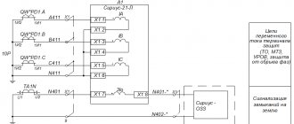
- For an indirect meter connection scheme, the secondary circuits should be routed to independent terminal assemblies or sections in a common row of terminals. If clamp assemblies are not available, test blocks must be installed. The clamps must ensure short-circuiting of the secondary circuits of current transformers, disconnecting the current circuits of the metering device and voltage circuits in each phase of the metering device when replacing or checking them, as well as turning on the model metering device without disconnecting wires and cables. The design of the assemblies and terminal boxes of the calculated metering devices must ensure the possibility of their sealing. (PUE clause 1.5.23).
Replacing electric meters – Electrics – Some tips
Home / Some tips / Electrics / Replacing electric meters
An electric meter is a device that keeps track of electricity consumed at home and in industrial enterprises. Today the market offers a wide selection of different counters, in order to choose the right one, you need to understand what they are.
Meters are divided by type of operation into induction and electronic. Induction meters are a cheaper option, while electronic ones are more reliable and accurate. There are also single-phase and three-phase meters for various networks.
The accuracy class of electricity meters is divided from 0.2 to 2.5. This figure shows the level of instrument error. Not long ago, a new GOST was introduced, according to which devices with an accuracy class of at least 2 percent can be used in everyday life.
note
Whereas previously a measurement error of 2.5 was allowed. Depending on the connection, electricity meters can be directly connected or connected via transformers. If the total load does not exceed 100 amperes, a direct connection meter can be used.
For larger loads, it should be connected via a current transformer.
There are 2 voltage classes: 220/380 V and 100 V.
There are single-tariff, double-tariff and multi-tariff models. Two-tariff devices allow you to take into account the amount of energy spent separately during the day and at night. The use of such devices helps to significantly save money. After all, the cost of energy differs by almost 2 times at different times of the day.