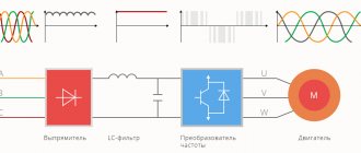
Most electrical machines are designed to operate at a stable voltage and frequency of the supply network. To control engine parameters (shaft power, rotation speed), it is necessary to change the supply voltage ratings. Voltage and frequency converters use transistors and thyristors. The latter are traditionally used for high-power devices, although the emergence of sufficiently powerful IGBT transistors makes it possible to gradually get rid of thyristor circuits due to their inherent shortcomings.
Powerful thyristor
The adjustment principles differ for DC or AC supply voltage.
Important! In industry, the abbreviation TFC refers to converters for induction heating systems for metals. For electric drives, the term used is variable-frequency drive or frequency converter for electric drive.
Literature
Gorbachev G. N., Chaplygin E. E. Industrial electronics: Textbook for universities / Ed. V. A. Labuntsova.. - M.: Energoatom-izdat, 1988. - 320 p.
Schilling V. Schemes of rectifiers, inverters and frequency converters: Per. with him.. - L.: Gosenergo-izdat, 1950. - 464 p.
Tolstov Yu.G. Autonomous current inverters. - M.: Publishing House "Energy", 1978. - 208 p.
Chizhenko I.M. Handbook of converter technology.. - K.: Tekhnika, 1978. - 447 p.
E. I. Berkovich. Thyristor high frequency converters. - L.: Energy, 1973.
Alfred Mühlbauer. History of Induction Heating and Melting. — Vulkan-Verlag GmbH, 2008.
John William Motto, Jr. Introduction to Solid State Power Electronics. — Westinghouse Electric Corp., 1977.
Takesi FUJITSUKA. Analysis and Design of Parallel Inverter Circuit with Parallel Inductive Load. — Kyoto University, 1971.
Nikolay L. Hinov. Parallel Inverter Analysis Using Mathematical Software. — Bulgaria: 1000 Sofia, 2005.
Pantech ProLabs India Pvt Ltd. Introduction to Parallel Inverter (English) (unavailable link). Retrieved September 22, 2014. Archived January 13, 2014.
Direct frequency converters
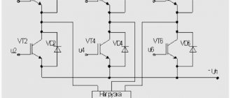
When using a CNC, voltage from the network is supplied through controlled valves to the engine. In each phase of the NPCh, a reversible two-set converter is installed with joint or separate control of the power sets.
In Fig. Figure 1a shows a diagram of a three-phase-single-phase VFC based on three-phase zero circuits. It converts three-phase voltage into single-phase voltage, but with an adjustable frequency. Sets B and H are switched, and the output is bipolar voltage. To control converters, certain control laws are used - rectangular and sinusoidal. If a rectangular control principle is used, then the operating algorithm will be as follows: when one half-wave of voltage passes, control pulses are applied to one of the sets with a control angle (delay angle) a = const. This kit will operate in rectifier mode and then with control angle (advance angle) b = a. To reduce the current it is necessary to switch to inverter mode (Fig. 1 b). To avoid a short circuit in the inverter itself, it is necessary for the current to drop to zero - this is called a dead time. After a dead pause, the second set is switched on.
If sinusoidal control is used, then the smooth component of the output voltage should change according to a sinusoidal law; for this, the control angle a continuously changes (Fig. 1 c).
Picture 1.
Diagram of a three-phase-three-phase NPCh, made on the basis of three-phase bridge circuits. Below is the diagram.
This type of converter is not widely used due to a number of disadvantages in its use. And this is: the impossibility of completely regulating the output frequency (when using three-phase bridge circuits, the control range is 25-45 Hz, and at zero 15-45 Hz). Constant switching of valves, which leads to deterioration of the power factor, as well as poor quality of the output voltage and a large impact on the supply network.
The advantage can be recognized that such converters have a higher efficiency due to a single energy conversion.
The most common are frequency converters based on AIT and AIN on IGBT transistors, due to the best energy quality indicators at the output of the converter and their impact on the network.
Trends in improving autonomous inverter circuits
The classification of thyristor autonomous inverters used in installations for induction heating of metals is carried out according to various criteria, but the main ones are natural and simple - these are, first of all, circuit characteristics: bridge, half-bridge or quarter-bridge circuits [3, 4].
It is advisable to determine the main trends in the development of technical solutions (TS) in the field of designing installations for induction heating of metals, as well as the current level of TFC design using patent information. The strict formulation of the subject of the invention in the patent - for the legal protection of the applicant's rights - allows us to determine the general goals achieved when implementing the circuit design of thyristor inverters.
We determined the generalized goals that are most often found among technical improvements in thyristor autonomous inverters for electrothermal processing of metals using the International Classification of Inventions (ICI). Descriptions of copyright certificates for class N02 M 7/72, 5/42 and others adjacent to them were analyzed for the period from 1985 to 1990, when the branch of technology in question received the greatest development.
The identified generalized goals and the number of AIs proposed in accordance with them are shown in the table.
Table. Generalized goals of AI technical solutions
| Paragraph | Achievable TR goals | Quantity TR |
| 1 | Increased reliability | 240 |
| 2 | Improved energy performance | 168 |
| 3 | Simplification | 165 |
| 4 | Reducing weight and dimensions | 30 |
| .. | .. | … |
| 24 | Galvanic isolation | 12 |
| 25 | Expansion of functionality | 6 |
The data presented show that the main focus when improving technical characteristics was on increasing reliability. If we take into account technical solutions that ultimately also increase reliability, it becomes clear that this goal was dominant. After analyzing this sample, you can be sure that in “second place” is improving energy performance and increasing efficiency. This goal in power electronics is achieved by reducing weight and dimensions (point 4).
Improving the energy characteristics of AI is, on the other hand, the path to the effective use of power circuit elements.
Finally, the remaining points of the table, small in number of technical solutions, are characterized by goals specific to the specific use of the circuit, for example, for a vacuum induction furnace, the requirement for galvanic isolation of the input and output circuits of the TFC is essential.
Particular attention should be paid to paragraph 25 “Expansion of functionality”. The practical absence of technical solutions to such a problem in the sample serves as a criterion that the analysis was carried out on solutions related to a specific technical problem. On the other hand, this shows that the universality of the use of TFC in installations for induction heating of metals is not always justified; on the contrary, the modern trend is to create specialized power plants with higher technical and economic indicators. The above does not exclude the use of standard circuits of autonomous inverters.
The generalized goals of technical solutions identified for the considered class of MPCs are justified by the “Methodology for assessing the quality of high-frequency and ultrasonic equipment” developed by the All-Russian Research Institute of High Frequency.
It is advisable to determine the technical level of TFC using a complex indicator based on expert assessments. This can be explained by well-known difficulties caused by the need to take into account conflicting factors. The task becomes more complicated if we take into account the ambiguous assessment of the advantages and disadvantages of using known circuits for the design of inverter-inductor electrical systems.
As a result, we have developed a library of technical techniques for improving circuit designs and technical characteristics of thyristor autonomous inverters, created based on the analysis of a large number of patent materials, and formulated some heuristic techniques that are effective in achieving these goals.
Inverters that generate a non-sinusoidal current shape at the output with higher harmonics, one of which is tuned to a resonant inductive load, are called polyresonant.
The possibility of the existence of combined circuits with mixed characteristics significantly complicates their classification, but helps to identify new properties of autonomous inverters, some of which turn out to be useful and are used in the design of power plants for induction heating of metals. Such schemes are novel and useful and are recognized as inventions.
The technical solution of the AI bridge circuit with freewheeling diodes [1] was the prototype of dozens of TFC inventions for induction heating of metals [2].
In Fig. 1 in the window of the demo version of MicroCAP 9 shows three classic circuits of thyristor autonomous inverters - converters of direct current into single-phase high-frequency current. These are a quarter-bridge inverter (aka single-ended, asymmetrical circuit), a half-bridge inverter and a bridge inverter with reverse current diodes.
Rice. 1. Three schematic diagrams of autonomous resonant inverters with freewheeling diodes
Reverse current diodes connected back-to-back with thyristors are traditionally used in Ufa converter circuits. They reduce the “swing” of voltage and stabilize the level of effective currents and voltages when the load resistance of an autonomous inverter changes in a wide range, characteristic of inverter-induction power plants.
Three circuits of autonomous inverters are connected to a common power source of 520 V, equal to the maximum rectified voltage of a bridge three-phase rectifier circuit connected to a standard supply network of 3 × 380 V - 50 Hz, as is the case in most cases when connecting powerful consumers.
At the input of these circuits, DC chokes with an inductance value of 4 mH are included. Chokes of this size are necessary to form the external characteristic of the AI as a current source and to limit the RF currents transmitted to the TFC power source. We assume that in the diagrams in Fig. 1 the same thyristors, diodes and power elements (switching capacitors and inductors) are used.
Let's set equal parameters of the switching elements (30 μF and 80 μH) and the same series equivalent active load resistance of 0.4 Ohms in each autonomous inverter circuit. Finally, we set the same frequency of switching on the thyristors.
Let's analyze the electromagnetic processes of these circuits in the circuit modeling program MicroCAP 9. The convenience of using this method of analysis lies in the clarity of the results, which are obtained in uniform coordinates for time, voltage, current and power.
In Fig. Figure 2 shows the time graphs we obtained of the steady-state value of the output current for these circuits.
Rice. 2. Timing diagrams of output currents of three autonomous inverters
The output current curve of the quarter bridge inverter circuit has the maximum amplitude. The output current curve of the inverter bridge circuit is minimal in amplitude. The load current curve of the half-bridge inverter circuit lies between them. The DC component of the output current for all circuits is zero, since the load is connected in series with the capacitor.
We will not discuss the significant difference in the amplitude of the obtained curves, but note that it completely depends on the value of the equivalent voltage in the electrical circuit with the thyristor for the moment of switching on.
The steady-state amplitude of the current after the end of the transient process, necessary for choosing the parameters of semiconductor elements, is calculated analytically, however, the moments of current switching by the thyristor and diode, necessary for the analysis of transient processes, are found by solving transcendental equations, which are practically not used in engineering practice.
3-phase frequency circuit diagram
Thyristor three-phase frequency converters are used to control powerful loads and are used where it is not possible to turn on equipment using IGBT transistors.
There are two classes of devices based on the principle of switching control elements:
- With single-stage switching;
- Two-stage.
Single-stage devices have a simple circuit design, but do not have the ability to adjust the output voltage, since all thyristors are controlled simultaneously. Voltage regulation occurs by installing a constant supply voltage in the circuit through the installation of an adjustable rectifier.
In turn, two-stage converters are divided into circuits:
- With group switching;
- With phase switching;
- With individual control.
These devices are more complex not only in the control circuit, but also in the power part, since they contain two groups of thyristors: anode and cathode.
Phase commutation
Control is carried out separately for each phase of the conversion by turning off the anode or cathode thyristor.
Individual switching
Here, each thyristor of the converter is controlled separately. Due to individual control, it is possible to implement a large number of conversion algorithms, reduce signal waveform distortion and the level of electromagnetic interference to a minimum.
Features of thyristor control
Frequency converter
Thyristors as switching elements are characterized by the fact that they can be used exclusively as switches. The catalog of thyristor nomenclature differs in that most of the elements in it do not require a constant supply of a control signal. This uses the property of thyristors to maintain an open state after removing control. Blocking occurs only when the current through the element drops below a certain level, or the polarity of the voltage at the anode and cathode changes.
You can avoid waiting for a polarity change or a decrease in current by using special turn-off thyristors, which are turn-off by applying a signal to the control electrode.
Any thyristor converter is characterized by a high level of voltage waveform distortion. Also, at the moment of switching, electromagnetic interference pulses occur, to reduce the level of which it is necessary to use additional circuit solutions (switching at the moment the voltage passes through zero, installing noise suppression filters).
Waveform distortion
Circuit solutions for converters based on thyristors
Frequency converter
A feature of thyristor circuits is that they are designed to work with a certain type of load.
Series and parallel current inverters
This type of converter has an additional capacitor connected in series or parallel to the load. The purpose of the capacitor is to ensure reliable locking of thyristors that are not involved in the passage of current through the power circuit. To stabilize the current through the load, the input of the current inverter contains inductance, which ideally should tend to infinity.
Combined schemes
The combined series-parallel circuit contains two capacitors and improves the load characteristics of the device. In particular, this scheme is more stable when operating at low loads.
McMurray voltage converter
The McMurray circuit includes an LC circuit. This circuit is formed from the connection of a capacitor and an inductor through a currently open thyristor, closing the opposite one.
This solution allows you to power an inductive load, for example, devices that perform induction heating or welding of metal structures.
Series resonant inverter
In such a circuit, the capacitor capacitance and inductance are selected in such a way that the circuit is in resonance at the LC conversion frequency. Thus, the thyristors will be controlled at the resonant frequency.
Conversion can be carried out at a higher frequency, which improves the characteristics of the circuit due to better switching conditions for key elements.
Types of converting units
The conversion can be performed by various schemes, in which the operating principle is different. There are several typical uses of thyristors:
- Controlled rectifiers;
- Inverter converters.
A controlled rectifier is characterized by the fact that instead of some or all diodes, thyristors are installed, by switching which at certain points in time you can control the average voltage across the load.
Controlled rectifier
A voltage converter based on thyristors, connected according to a controlled rectifier circuit, due to the nature of its operation, can only be used in alternating current circuits to supply the load with direct voltage.
Inverter converters generate voltage, close to sinusoidal in shape, from direct voltage. In this case, a different number of phases can be obtained, and it is possible to adjust the voltage amplitude and frequency.
A frequency converter
In order to control power and speed, an asynchronous motor can only be switched on through an inverter converter (frequency drive).
IGBT transistors
By combining the positive qualities of bipolar and field-effect transistors with an insulated gate, you can obtain a very worthy switching element for low-frequency (meaning industrial frequency 50-60 Hz) technology - IGBT.
Its designation and simplified equivalent circuit are shown in the figure above. The circuit is assembled similarly to Darlington for bipolar. A field-effect transistor with an n-channel actually serves as a current amplifier with high gain, and well opens the bipolar transistor associated with it, which serves as a power transistor in this pair. Its emitter in this structure is called a collector and vice versa (according to the “duck principle” - in relation to the terminals, the device partly behaves like a bipolar transistor with a giant gain). At the same time, IGBT cannot be considered a simple circuit that is “soldered together” from n-channel field-effect and pnp bipolar transistors - this is precisely a semiconductor structure, not a circuit. The formal base-collector junction of the bipolar part and the field channel form a single structure on the crystal.
The scope of application of IGBT transistors in terms of electrical parameters lies from 300 V and above, in terms of frequency - up to 10 kHz. This is just well suited for industrial frequency (in the use of frequency generators). IGBTs are used in electric drives ranging from small power tools to electric locomotives. The fact that they operate in the region of not very high frequencies, unlike mosfet, eliminates many problems associated with parasitic inductances and capacitances - the control transistor in such a structure feels quite comfortable, its switching frequency is relatively low. This means it is easier to reload the bolt capacitance.
In this case, high conductivity is not required from it. The output PNP bipolar transistor is designed in such a way that it can withstand high reverse voltage and can operate in inverse mode. The ease of control of IGBTs and the range of safe operation turned out to be much higher than that of bipolar transistors. IGBTs, as such, do not have a built-in flyback diode, but such a fast recovery diode can be added to the circuit either externally or integrated on-chip if needed for the application for which the device is intended.
IGBTs appeared in 1983 (the first sample was patented in IR)
The first samples did not switch well and were unreliable, so they did not enter the market properly. The difficulties were technological, related to obtaining plates with a thickness of about 100 microns
Overcoming them, as well as the emergence of Trench technology for the manufacture of MOSFETs, made it possible to sharply reduce the channel resistance in the open state, and this made it possible to bring the properties of IGBT closer to the properties of a traditional mechanical switch, but without the inherent arcing and with several orders of magnitude high performance.
IGBT transistors are used in frequency converters and soft starters; they are rapidly replacing thyristors in all areas, despite their significant price. It is used in power supplies, inverters, electric drives, welding power devices, and in transport.
Load operating principle. 3-phase frequency circuit diagram
The diagram shows the operating energy of the frequency generator. A similar diagram is made for a bridge circuit. It is more often used when designing a frequency generator for loading equipment and machine tools. The phase voltage in the circuit is increased.
A single-phase circuit is used for the power line, operating a mechanism with high inductance resistance. It operates in the power range of 10 – 20 kW, rarely at significant powers. For an electric furnace or machine in everyday life, the following scheme is used:
A three-phase circuit diagram is used for 20 kW mechanisms, synchronous motors, excavators and cranes. A popular multi-phase circuit is the 6-phase circuit. It involves the use of a low potential and high current equalizer. A current-carrying device conducts and changes electrical energy in parallel, unlike many similar devices. It is difficult to make, but its reliability is greater than that of single-phase thyristors. This controller with reverse has a negative side - its efficiency is less than 70%.
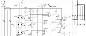
It is possible to make your own thyristor frequency converter, depending on the basis of the application. The figure shows a circuit based on Micro-Cap 9. The main advantage is the need to load several nodes together.
Development
The electrical circuit of a thyristor converter-motor (for example, KHP) for smooth switching can be of two types:
Depending on the type of design, the ratios of calculation units and the operating principles of the converter vary.
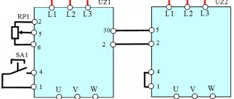
Photo - zero circuit of three-phase conversion
This drawing schematically shows the change in electrical energy when the thyristor converter operates in rectifier and inverter mode. At the same time, for a bridge circuit you can make the same diagram, but only consisting of two zeros. It is this type that is most often used when designing converters for machine tools. This is due to the fact that the initial phase voltage in it is twice the phase voltage (Udo) in the zero operating circuit.
Photo - food
A single-phase circuit is used to control the power supply and drive operation of machines with high inductive reactance. It operates within a power range from 10 kW to 20, much less often at higher powers. For example, suitable for an electric oven or home machine.
Photo - single line diagram
Three-phase is used for equipment where 20 kW or more is required for operation. For example, for synchronous drives, crane and excavator engines. Another popular multiphase control circuit is six-phase (Camron). Her project involves the use of a surge reactor in the design, which is aimed at controlling low voltage and high current. This power electrical device transmits and converts electrical energy in parallel rather than serial (like most similar devices). It is more difficult to develop with your own hands, but the degree of reliability and efficiency is much greater than that of a single-phase thyristor converter. But such a reversible controller has a serious drawback - its efficiency is less than 70%.
Determination of the amount of converted power
Where should you start the calculation? The most important parameter of any power source is power. All other parameters of the converter, including weight, dimensions and cost, directly depend on it. In this case, the output power of RO can be easily determined as the sum of the powers of both channels:
| (1) |
where ROUT1, ROUT2 are the output power of the first and second channels, respectively.
However, in fact, the key influence on the mass, dimensions and cost is not the output, but the converted power of the RPM - the rate of energy transfer through the magnetic or electric fields of elements that change the parameters of electrical energy. In our example, this process occurs in inductor L1, therefore all other parameters of the circuit depend on its operating mode.
In general, the amount of converted power may be less than the power of the converter. This is due to the fact that, due to the design features of the power section, part of the energy is supplied to the load directly from the primary power source (from the converter input), bypassing the magnetic field of the inductor. This issue is discussed in detail in [], where formulas are obtained that allow one to calculate the RPM value for the four most common (“basic”) schemes:
| (2) |
where UIN, UOUT are, respectively, the voltage at the input and output of the converter.
Our scheme, at first glance, is not one of the “basic” ones, but let’s look at it carefully. If you mentally remove from it all the elements related to the second conversion channel (winding W2, VD1, C3), then you will be left with a classic boost converter, and if you remove the elements of the first channel (VD2, C2), then you will be left with a flyback converter (Figure 3).
| Figure 3. | Dividing the circuit (Figure 1) into elementary “basic” converters. |
For the first channel (boost circuit), the converted power of RPM1 depends on the ratio of the input and output voltages, and the greater the voltage difference, the greater RPM1. Let's determine this value for the worst case - at the minimum input voltage UВХ_MIN:
| (3) |
In the second channel (flyback circuit), all energy passes through the magnetic field of the inductor, therefore the converted power of RPM2 does not depend on the ratio of the input and output voltages:
| (4) |
The magnetic circuit of the inductor L1 is common to two channels, therefore, using the principle of superposition, the total converted power of the RPM can be represented as the sum of the converted powers of the first and second channels:
| (5) |
Comparing the results of calculations using formulas (1) and (5), we see that RPMOUT. The missing 4 W due to electrical communication are supplied to the load of the first channel directly from the input without any conversion. This allows us to make our circuit almost 17% smaller and lighter than if both channels were connected via a flyback circuit (Figure 2b). By the way, if the reader wants to practice calculating the converted power, then Figure 2 shows the results of the RPM calculations for all inductive components, which can be used for self-test.
Criteria for the efficiency of using thyristors
The criterion for the efficiency of using power elements in various circuits of autonomous inverters was previously considered the total installed power of similar elements in comparison with the output power of the circuit. This criterion quite fully characterizes power capacitors and inductive elements (in terms of kVAr value). However, power semiconductor elements - thyristors, diodes, IGBT modules - do not completely depend on it.
For thyristors, at one time, criteria such as n (Um × Jm) were used, where n is the number of thyristors, Um and Jm are the maximum voltage and current of the thyristors. Various combinations of products of the main parameters with empirical coefficients were proposed - (k1 Um), (k2 Jm), (k3 du/dt), (k4 di/dt), (k5 trestore), etc.
At present, it is advisable to use a single estimate for all semiconductor elements of basic power circuits, as which it is necessary to take the cost of the same type of component elements for products with the same generalized parameters.
A generalized TFC parameter for induction heating can be the product of the rated output power and operating frequency because power inverters 320 kW × 1000 Hz, 80 kW × 4 kHz, 20 kW × 16 kHz have the same cost of components. Let us explain that for a quarter bridge circuit, according to Fig. 1, the design requires 4 thyristors connected in series, in a half-bridge circuit 2 × 2 thyristors are required, the minimum number of thyristors for a bridge circuit is 4.
The price of an electrical product in the most general case is determined by the cost of component elements, production costs and the cost of the intellectual component, which can include the distinctive properties of the product, for example, an extended output frequency control range. This approach meets modern requirements.
Note that during circuit modeling in MicroCAP, in addition to the power (POWER) of the power diode, you can also fix other parameters, for example, its cost, as shown in Fig. 3.
Rice. 3. Panel of power diode parameters for an autonomous inverter in the working window of the MicroCAP program
In Fig. Figure 3 shows the diode parameters panel (on the left) in the working window of the MicroCAP 9 circuit modeling program. The panel shows the cost (COST) of the applied diode type in the list of elements showing the total cost of the electrical circuit (help at the bottom of the panel).
The first and second levels of representation of the element model (LEVEL) for a power semiconductor diode make it possible to simplify calculations when studying transient processes, frequency analysis, Fourier decomposition, etc. in circuit modeling procedures of the circuit under study. At the same time, varying the parameters of an element, according to the stepping procedure for the listed types of analysis, is possible only for such parameters that, it turns out, do not significantly affect the cost of the element.
In the Transient analysis menu, the operating temperature of the circuit is set, which refines the results of calculating transient processes when modeling a diode as an element of the highest third level.
Note that the weight and dimensions of static converters, like many other power electronics products, currently have a significant tendency to decrease with increasing operating frequency. This difference is reduced by the surface effect, in which conductors have a reduced effective cross-section due to the depth of current penetration, and an increase in eddy current losses in structural materials.
Operating principle and design features
To convert the load, a thyristor high-voltage circuit converter based on IGBT is used. A thyristor-based frequency converter is a device for converting current, adjusting its parameters and current level. Using a frequency converter, you can equalize the values of drive parameters on electric motors: angle, shaft speed at startup, and others.
Thyristor equalizer circuit.
For a DC motor, a thyristor converter is used. The advantages of this device have allowed it to be widely used. Benefits include:
- Efficiency (95%) for the PN-500 brand.
- Control area: motors from low power to megawatt.
- Can withstand significant impulses of engine starting loads.
- Durable and reliable operation.
- Accuracy.
This system also has disadvantages. Power is at its lowest level. This is evident in the precise regulation of the production process. Additional devices are used as compensation. Such a frequency converter cannot operate without interference. This can be seen during the operation of sensitive electrical equipment and radio devices.
Components:
- Reactor in the form of a transformer.
- Current rectification blocks.
- Reactor for smoothing the transformation.
- Overvoltage does not affect the protection.
Converters (2017) are connected through a reactor. The transformer serves to match the output and input voltage sections and equalize the voltage between them. The electrical connection circuit includes a smoothing reactor. The frequency converter has a circuit that contains a smoothing reactor.
The frequency converter passes the load. The load goes to the rectifier blocks in the output link. To equalize the power supply of several devices, induction consumers are connected on special buses.
There are two types of frequency converters - high-frequency and low-frequency. The selection of the desired model is carried out according to the necessary parameters of the electrical circuits. In 3-phase machines, the connection type is different. 1-phase current tolerates impacts, but efficiency is lost when converting to 3-phase current.
The system is used in smelting production, control of lifting and transport devices, and welding production. This principle of load operation is implemented by an engine-generator system. At the lowest engine speeds, the spindle speed is adjusted over a wide range and different characteristics of the motor drive are adjusted.
Technical data and cost
The characteristics of thyristor frequency drivers depend on the type and options.
TFC
| Values | TFC 320 | 800 |
| power, kWt | 320 | 800 |
| Maximum power, kVA | 640 | 1250 |
| Frequency, hertz | 50 | 50 |
| Input voltage, V | 380 | 500 |
| Maximum direct current value, A | 630 | 1000 |
| Efficiency, % | 94 | 94 |
| Output voltage, V | 800 | 1000 |
A thyristor-based converter operating in conditions with humidity and dust (EPU-1-1-3447E UHL4).
| Current, A | 25 |
| Maximum load current, A | 100 |
| Input voltage, V | 380 |
Thyristor converters are combined into rectification complexes. If one equalizer malfunctions, all equipment is completely repaired or dismantled. In the rectifier complex, only the mechanism that has failed is replaced. These systems are used in machine tools. The cost of equipment for the ABB DCS400 thyristor converter for 2022 is around one hundred rubles.
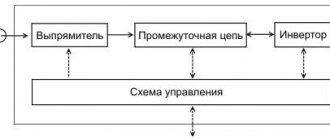
Frequency converters with DC link
These are devices made using a transistor or thyristor circuit. However, their main distinguishing feature is that the correct and safe operation of the frequency generator requires the presence of a constant voltage link. Therefore, to connect them to an industrial network, a rectifier is required. Typically, complete equipment is used, consisting of a frequency converter and rectifier, controlled by one control system.
The inverter of this group uses a two-stage conversion of electricity: sinusoidal U input with f = const is straightened in the rectifier (V), filtered by a filter (F), smoothed, and then re-converted by the inverter (I) into U ̴. Due to the two-stage conversion of electricity, the efficiency decreases and the weight and size indicators slightly deteriorate in comparison with frequency converters with direct coupling.
To create a sinusoidal U ̴ self-controlled frequency converters. They use an advanced thyristor and transistor base as the key base.
The main advantage of thyristor converter equipment is the ability to operate with large network parameters, while withstanding continuous load and pulsed influences. The devices have higher efficiency.
Frequency converters based on thyristors today are superior to other high-voltage drives, the power of which amounts to tens of MW with U out from 3 to 10 kV and more. However, their price is correspondingly the highest.
Advantages:
- highest efficiency;
- possibility of use in powerful drives;
- reasonable cost, despite the introduction of additional elements.
TFC with direct galvanic connection to the power supply network
This solution can be called one of the simplest in terms of implementing the principle of electric motor control. This circuit allows you to generate supply voltages at the output with a given frequency and phase. It must be emphasized that the frequency of the output signal cannot exceed the frequency of the supply voltage, therefore such systems are used mainly for powerful low-speed engines.
The circuit design includes a combination of thyristor electronic switches, which can be:
- manageable;
- uncontrollable;
- included back-to-back;
- included according to the bridge scheme;
- cross-connected;
- connected according to zero circuits.
All these connections are used in one TFC with galvanic coupling and provide the formation of an output sinusoidal signal from fragments of the input sinusoidal signal. These fragments are formed in such a way as to obtain an output signal with the required frequency and phase.
However, such a seemingly simple circuit solution has a number of disadvantages, which include:
- complex shape of the output signal. It is not sinusoidal, so it can lead to additional vibrations, as well as harmonic interference in the supply network;
- limited engine speed, which, as a rule, cannot exceed the rated frequency of the supply network;
- a complex key management scheme, which either requires complex configuration or the use of a digital control system, the complexity and cost of which are also quite high.
At the same time, this solution also has advantages, thanks to which it is still used to control electric motors operating at low speeds and under heavy load. Among the advantages of this solution are:
- cost of equipment. The price of such a TFC is significantly lower than the cost of a frequency converter based on transistor elements with similar parameters of load power and control range;
- high system efficiency, within 95%;
- maintaining the voltage amplitude of the input network at the output of the converter;
- the ability to operate in regenerative mode when the engine is used in generator mode when braking;
- a simple possibility of upgrading the TFC when increasing the load power by adding parallel thyristor modules, while the power can theoretically be increased almost indefinitely.
Classification of converters
Based on the type of valves used, static converters are divided into ionic (gastronic, mercury) and semiconductor (silicon, selenium, germanium, etc.); by type of valves - diode, thyristor and diode-thyristor; since the 1990s, transistor converters have become widespread. Rolling stock traction converters currently use gated thyristors (GTOs) and IGBT transistors, depending on the drive power.
According to the functions performed, rectifier converters, inverter converters and rectifier-inverter converters are distinguished; according to the method of voltage regulation - pulse (direct current), pulse-phase, zone-phase, frequency, pulse-frequency, pulse-width, etc.
Static converters can be dependent on the supply voltage (for AC EPS) and independent (for DC EPS); are carried out with natural and forced cooling, air and liquid (oil), as well as thermosyphon.
Structurally, static converters can be stationary and mobile, on EPS, in-body (in-car) and under-car.
Static converters of power circuits of substations and EPS are manufactured in the form of cabinets or panels in which valves are installed. According to the connection diagram of the valves, static converters are distinguished: 2-, 4-arm (bridge), 6-, 8-, 10-arm and others with series-parallel connection of valves.
The EPS uses static converters in traction design (see Fig.) with electric valves, made taking into account the relevant technical conditions. In low-power, low-voltage static converters, valves of general technical manufacture are used.
Semiconductor static converters are also common on the railway, they are more reliable compared to mercury ones, have smaller overall dimensions and weight, longer service life, and are non-toxic during maintenance and repair.
Static converters for EPS must provide:
EPS operability without power limitations in case of failure of one of the valves (in any arm) and in case of damage in control circuits; convenient and quick replacement of damaged valves;
stable operation when the value and shape of the supply voltage changes within the established limits.
During operation, static converters open and close in accordance with a given control algorithm, resulting in current flowing into the load at certain periods of time. One or more power static converters are installed on the EPS, each of which powers one or more traction motors. The power of such static converters is up to several thousand kW, the operating voltage is from units to several thousand V; current strength - from units to several thousand A.
Improvement of static converters is possible in the direction of improving their parameters, reducing overall dimensions and weight, reducing the number of valves while providing the same power, increasing reliability, simplifying the maintenance and repair system.
Types of converters
Among the variety of existing types of converters, the following classes are distinguished:
- special devices for home;
- high-voltage and high-frequency equipment;
- transformerless and inverter pulse devices;
- DC voltage converters;
- adjustable devices.
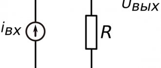
This category of electronic devices includes current-to-voltage converters.
Equipment for home
The average user encounters this type of converter devices all the time, since most models of modern technology have a built-in power supply. The same class includes uninterruptible power supplies (UPS) that have a built-in battery.
In some cases, household converters are made using a double ring (inverter) circuit.
Due to this conversion from a direct current source (a battery, for example), it is possible to obtain an alternating voltage of a standard value of 220 Volts at the output. A feature of electronic circuits is the ability to obtain a purely sinusoidal signal of constant amplitude at the output.
Adjustable devices
These units are capable of increasing the output voltage and increasing it. In practice, more often there are devices that allow you to smoothly change the reduced value of the output potential.
The classic case is when the input is 220 Volts, and the output produces an adjustable constant voltage ranging from 2 to 30 Volts.
Transformerless devices
Transformerless (inverter) units are built according to the electronic principle, which involves the use of a separate control module. As an intermediate link, they use a frequency converter, which converts the output signal to a form convenient for rectification. In modern models of inverter equipment, programmable microcontrollers are often installed, which significantly improve the quality of conversion control.
High-voltage devices are represented by the already described station transformers, which increase and decrease the transmitted voltage in the required ratios.
When transmitting energy through high-voltage lines and subsequent transformation, they strive to reduce its losses in watts to a minimum.
This class also includes devices that generate a signal to control the beam in a television tube (kinescope).
Insulated Gate Bipolar Transistor
The title of this section translates to “insulated gate bipolar transistor.” This is a modern device that appeared around the end of the last century and made a revolution in power electronics. Electricity has been used by mankind for a long time; with the development of technology, one part of the emerging problems was successfully solved, such as the abandonment of expensive magnetic alloys in favor of cheap steel and copper field windings in DC motors and magnets (Werner Siemens). The other part of the problems remained stubbornly resistant to solution for a long time. This includes, for example, the use of alternating current in electric vehicles.
Electrical devices always contain switching elements and these are their most painful areas. When many electrical circuits break, an arc occurs that burns out the contacts over time. The contact resistance should ideally be no more than the smallest section of the rest of the circuit, but in practice, it is thanks to the oxides from the arc that increased resistance occurs at the contact point. According to the Joule-Lenz law, thermal power appears and dissipates at this resistance, proportional to the resistance and the square of the current. Heating of the contact point by current leads to its accelerated aging, the further, the faster, and as a result the circuit fails.
Advantages of thyristor converters
TFCs have been very widely used due to their many advantages. The main advantage of thyristor converters in comparison with electric machine converters is that due to high efficiency, as well as the absence of no-load losses, there is a tendency to reduce power consumption from the network, and at the same time operating costs are reduced. Also, a great advantage of thyristor frequency converters is their regulation properties. Regulation of output parameters and power can be carried out without switching in power circuits. This eliminates the need for large switching devices.
Before you decide to buy a frequency converter, you need to familiarize yourself with its advantages, namely:
- high-quality element base from European manufacturers;
- high reliability and durability;
- simplicity and ease of use;
- high efficiency 93-95%;
- high resistance to short circuits in the load;
- ability to withstand powerful pulse overvoltages at the input;
- internal self-diagnosis and protection of all power elements;
- remote control and regulation from the remote control panel;
- digital display of converter parameters;
- cooling of the TFC is water double-circuit with a heat exchanger;
- the ability to adapt to existing equipment;
- easily reconfigurable parameters;
- individual modification at the request of the Customer;
- prompt delivery of components and spare parts;
- warranty and service;
- training of customer personnel;
- replacement of obsolete machine generators with TFCs.
Thyristor frequency converters ТПЧ-350-1 Thyristor frequency converters ТПЧ-350-1 Thyristor frequency converters ТПЧ-1600-0.5 Thyristor frequency converters Thyristor frequency converters ТПЧ-350 Thyristor frequency converters and induction furnace
Specifications
| Converter type | power, kWt | Operating frequency, kHz | Supply voltage, V | Output voltage, V |
| TFC-100-2.4 | 100 | 2,4 | 380 | 800 |
| TFC-100-8.0 | 100 | 8,0 | 380 | 800 |
| TFC-160-1.0 | 160 | 1,0 | 380 | 800 |
| TFC-160-2.4 | 160 | 2,4 | 380 | 800 |
| TFC-160-8.0 | 160 | 8,0 | 380 | 800 |
| TFC-250-1.0 | 250 | 1,0 | 380 | 800 |
| TFC-250-2.4 | 250 | 2,4 | 380 | 800 |
| TFC-250-8.0 | 250 | 8,0 | 380 | 800 |
| TFC-350-0.5 | 350 | 0,5 | 380 | 800 |
| TFC-350-1.0 | 350 | 1,0 | 380 | 800 |
| TFC-350-2.4 | 350 | 2,4 | 380 | 800 |
| TFC-400-0.5 | 400 | 0,5 | 380 | 800 |
| TFC-400-1.0 | 400 | 1,0 | 380 | 800 |
| TFC-400-2.4 | 400 | 2,4 | 380 | 800 |
| TFC-500-0.5 | 500 | 0,5 | 380 | 800 |
| TFC-500-1.0 | 500 | 1,0 | 380 | 800 |
| TFC-500-2.4 | 500 | 2,4 | 380 | 800 |
| TFC-650-0.5 | 650 | 0,5 | 380 | 800 |
| TFC-650-1.0 | 650 | 1,0 | 380 | 800 |
| TFC-650-2.4 | 650 | 2,4 | 380 | 800 |
| TFC-800-0.5 | 800 | 0,5 | 570 | 1000 |
| TFC-800-1.0 | 800 | 1,0 | 380/570 | 800/1000 |
| TFC-1200-0.5 | 1200 | 0,5 | 570 | 1000 |
| TFC-1200-1.0 | 1200 | 1,0 | 570 | 1000 |
| TFC-1600-0.5 | 1600 | 0,5 | 900 | 1800 |
| TFC-1600-1.0 | 1600 | 1,0 | 900 | 1800 |
| TFC-2000-0.5 | 2000 | 0,5 | 900 | 1800 |
Why is it worth buying a frequency converter from Termolit LLC
Today, Termolit is a leader in both the domestic and foreign markets of induction equipment. Deliveries are made to Russia, Belarus, Poland, Estonia, Germany, Israel and many other countries.
The Termolit enterprise produces a wide range of modern induction equipment, in particular thyristor frequency converters of the TFC series of various powers.
Scope of delivery: TFC cabinet and operational documents. Also, for an additional cost, the following can be supplied: replaceable backup control units, a repair kit, spare parts, and a remote control. The purpose of replaceable backup units is to reduce the time to restore functionality in the event of a malfunction in the TFC control system, as well as to reduce the changeover time when operating one TFC for different loads in turn.
The Termolit enterprise today is:
- affordable prices from the manufacturer;
- order execution in the shortest possible time;
- the quality of manufactured equipment is at the highest level;
- the possibility of individual development of equipment at the customer’s request;
- reliability and durability of products.
In order to buy a frequency converter at an affordable price, contact Termolit. You will purchase quality equipment directly from the manufacturer, without overpaying to intermediaries. The company provides warranty and post-warranty service on mutually beneficial terms with the customer.
HIGH FREQUENCY TRANSISTOR GENERATOR INVERTER FOR INDUCTION HEATING
Digital microprocessor control system TFC 320
Microprocessor control systems TFC 320 regulate, protect and diagnose. It is formed on a board with microcircuits and a screen through cables. This system guarantees reliable operation and protects against interference.
An impulse is transmitted to each valve. The information is displayed on the panel screen. Information can be obtained from the circuit mechanisms. The control system processes a lot of data transmitted via communication. This is the data:
- Power.
- Frequency.
- Loading weight.
- Weight of molten metal.
- Time.
Complete set of cabinet TFC 320:
- Rectifier.
- Power leveling system.
- Smoothing throttle.
- Diagnostics.
- Temperature control.
- Cooling control.
- Door lock.
- Protection, restart of the frequency generator when the power line is disconnected.
Operating conditions TFC 320
| № | Condition | Meaning |
| 1 | Room with temperature | from +5° C to +35° C (UHL 4) and from +5° C to +45° C (TS 4); |
| 2 | Height no more than: | 1000 m; |
| 3 | Humidity up to: | 80% at +25° C (UHL 4) and 98% at +35° C (TS 4); |
| 4 | Wednesday: | Safe, no corrosive gases |
| 5 | Protection GOST 14254-80 | IP 55 |
| 6 | Interference level is not higher than: | GOST 23450 - 79 |
Reversible thyristor converters Operating principle and design
IGBT modules
Since IGBTs, as a rule, are extremely rarely used in a single version, designers began to think about modular options for their layout. The module is much simpler and more compact to use in products. But not only that.
However, the intervention of sufficiently qualified engineers will be required, since we are talking about reworking the frequency circuit, since not all models allow such an expansion: there are no outputs for such connections, and not a word in the instructions, except, perhaps, a ban on interfering with converter diagram on the consumer side and disclaimer for such cases. In addition to the technical side of the matter, there is also a possible legal one: possible violation of patents, licenses, etc. This should also be kept in mind.
Circuit solutions for converters based on thyristors
A feature of thyristor circuits is that they are designed to work with a certain type of load.
Series and parallel current inverters
This type of converter has an additional capacitor connected in series or parallel to the load. The purpose of the capacitor is to ensure reliable locking of thyristors that are not involved in the passage of current through the power circuit. To stabilize the current through the load, the input of the current inverter contains inductance, which ideally should tend to infinity.
Combined schemes
The combined series-parallel circuit contains two capacitors and improves the load characteristics of the device. In particular, this scheme is more stable when operating at low loads.
Serial, parallel and combined circuits
McMurray voltage converter
The McMurray circuit includes an LC circuit. This circuit is formed from the connection of a capacitor and an inductor through a currently open thyristor, closing the opposite one.
McMurray scheme
This solution allows you to power an inductive load, for example, devices that perform induction heating or welding of metal structures.
Series resonant inverter
In such a circuit, the capacitor capacitance and inductance are selected in such a way that the circuit is in resonance at the LC conversion frequency. Thus, the thyristors will be controlled at the resonant frequency.
Conversion can be carried out at a higher frequency, which improves the characteristics of the circuit due to better switching conditions for key elements.
Diagram of a model of an induction complex using thyristors
Induction heating devices most often use a McMurray circuit or a resonant converter, since the load is clearly inductive. Induction heating devices consume significant current, so thyristors are used in powerful furnaces, despite transistors with better parameters.
Since three-phase alternating current is used to power industrial facilities, the design necessarily contains a rectifier that produces direct current at the output.
The use of thyristors as key elements of the inverter allows you to create simple and reliable circuits, the main disadvantage of which is quite strong distortion of the voltage waveform and a high level of electromagnetic interference.
How to make a frequency converter yourself
Many hobbyists try to make frequency converters with their own hands.
Homemade inverter circuit
The circuit works well with a motor with a power of up to 1 kW, made in Russia and abroad.
To make an inverter you will need the following parts:
- microcircuits: K155LA3, K155IE4, K155LP5;
- transistors: KT315 (3 pcs.), KT817V (3 pcs.);
- diodes: KD105G – 3 pcs.;
- resistors with resistance: 10 kOhm (3 pcs.), 6.2 kOhm (3 pcs.), 1 kOhm (3 pcs.), 220 Ohm and a variable resistor of 1 kOhm;
- capacitors: 0.33 and 0.1 µF;
- electrolytic capacitors: 100 µF*10 V and 1000 µF*50 V.
This self-made frequency generator definitely needs a 27 V and 5 V DC power supply. The electric motor is connected according to the diagram.
Including an electric motor in a circuit
If we turn to modern technologies, then the creation of an inverter can be done on the basis of the Arduino platform. Frequency regulators are an indispensable thing for controlling electric drives, both in domestic and industrial environments.
Three-phase inverters
Thyristor (GTO) traction converter according to the Larionov-star scheme
Three-phase inverters are typically used to produce three-phase current for electric motors, such as to power a three-phase induction motor. In this case, the motor windings are directly connected to the inverter output.
High-power three-phase inverters are used in traction converters in the electric drive of locomotives, motor ships, trolleybuses (for example, AKSM-321), trams, rolling mills, drilling rigs, and in inductors (induction heating installations).
The figure shows a diagram of a thyristor traction converter according to the Larionov-star circuit. Theoretically, another version of Larionov’s “Larionov-triangle” circuit is possible, but it has different characteristics (equivalent internal active resistance, copper losses, etc.).
Typical design and operating principle
A thyristor is a semiconductor made of silicon. Typically, it consists of four conductive layers. The assembly is carried out on a copper base, which has six sides and a threaded shank. This element is complemented by a main structure, in the production of which special silicon is used.
The four-layer transmission complex has two outputs - control and negative. From the outside, the entire structure is protected by an iron casing shaped like a cylinder and equipped with an insulating layer. Using a thread, the thyristor is installed in a special mounting location and connected to the positive pole of the power circuit with anode voltage.