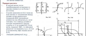
The quantity characterizing the amount of energy losses that occur when current flows through its source is defined as the internal resistance of the current source. Like regular resistance, it has a unit of measurement equal to 1 ohm. The current, moving through the source, loses part of its energy, which turns into heat, just like at any load resistance. This means that the voltage value at the source terminals depends on the current value, and not on the EMF.
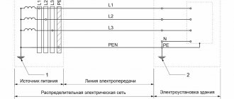
Dependence of the voltage between its terminals on the source current
If we consider a closed electrical circuit that includes a current source (battery, accumulator or generator) and a load R, then the current flows inside the source. The internal resistance of the source, denoted by the letter r, prevents it.
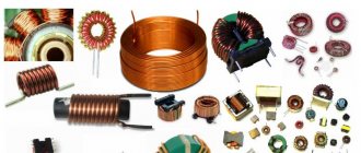
For a generator, r is the internal resistance of the stator windings; for a battery, it is the resistance of the electrolyte.
Internal resistance of the current source.
Let there be a simple closed circuit consisting of a current source (for example, a galvanic cell, battery or generator) and a resistor with a resistance R. The current in the closed circuit is not interrupted anywhere, therefore, it also exists inside the current source. Any source represents some resistance to current. It is called the internal resistance of the current source and is denoted by the letter r.
In a generator, r is the winding resistance; in a galvanic cell, it is the resistance of the electrolyte solution and electrodes.
Thus, the current source is characterized by the values of EMF and internal resistance, which determine its quality. For example, electrostatic machines have a very high EMF (up to tens of thousands of volts), but at the same time their internal resistance is enormous (up to hundreds of megohms). Therefore, they are unsuitable for generating high currents. Galvanic cells have an EMF of only approximately 1 V, but the internal resistance is also low (approximately 1 Ohm or less). This allows them to obtain currents measured in amperes.
Copper-zinc element
It is interesting to consider the principle of operation of galvanic cells using the example of a copper-zinc galvanic cell, the action of which comes from the energy of zinc and copper sulfate. In this source, a copper plate is placed in a copper sulfate solution and a zinc electrode is immersed in a zinc sulfate solution. The solutions are separated by a porous spacer to avoid mixing, but they must come into contact.
If the circuit is closed, the surface layer of zinc is oxidized. In the process of interaction with the liquid, zinc atoms, turning into ions, appear in the solution. Electrons are released at the electrode, which can take part in the formation of current.
Once on the copper electrode, electrons take part in the reduction reaction. Copper ions come from the solution to the surface layer; during the reduction process, they turn into copper atoms, depositing on the copper plate.
Let's summarize what is happening: the process of operation of a galvanic cell is accompanied by the transition of electrons from the reducing agent to the oxidizing agent along the external part of the circuit. Reactions occur on both electrodes. An ion current flows inside the source.
Internal resistance of the EMF source
The thing is that a resistance is “hidden” in the battery, which, relatively speaking, clings in series with the source of the battery’s emf. It is called internal resistance or output resistance. Indicated by a small letter “r”.
It all looks like this in the battery:
We hook the light bulb
So, what do we get in its pure form?
A light bulb is a load that has resistance. So, we simplify the diagram even more and get:
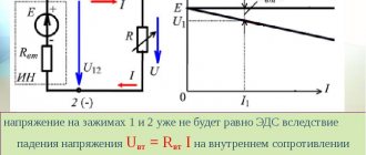
We have an ideal EMF source, internal resistance r and load resistance R. Recall the article voltage divider. It says that the voltage of the EMF source is equal to the sum of the voltage drops across each resistance.
The voltage UR drops across the resistor R, and the voltage Ur drops across the internal resistor r.
Now let's remember the article current divider. The current flowing through series-connected resistances is the same everywhere.
Let's remember algebra for 5th grade and write down everything that we just talked about. From Ohm's law for a section of the chain we obtain that
Further
How is internal resistance measured?
To determine the value of the characteristic under consideration, measurements are used during a direct short circuit of the terminals, which is called a short circuit. As you know, if you short-circuit the terminals of a source, a significant current will flow between them. This is often the result of carelessness and leads to burning of the insulation and melting of the wire.
During a short circuit, the circuit resistance becomes minimal. By accurately measuring the current in this situation and knowing the voltage at the terminals when there is no load, you can determine the internal resistance of the power supply. To do this you will need the following formula:
r = U / I(deputy), where
- the letter r denotes the internal resistance of the current source;
- U is the potential difference at the battery terminals without connection to the electrical circuit;
- I(deputy) - the current that passes when the terminals are directly connected to each other.
Finding the load value in this way is not always possible or practical, since a short circuit can cause a serious accident.
Therefore, other solutions to the question of how to find the internal resistance of a source are used. For example, using special measuring instruments. The original iMax B6, ToolkinRC M8, M6, M600 chargers are equipped with the function of measuring this parameter.
Methods for charging batteries
Using batteries will drain them. Reconditioning batteries and charging small-sized cells is carried out using a current whose strength does not exceed one tenth of the source capacity.
The following charging methods are available:
- using constant current for a given time (about 16 hours with a current of 0.1 battery capacity);
- charging with a decreasing current to a given potential difference;
- use of asymmetrical currents;
- sequential application of short pulses of charging and discharging, in which the time of the first exceeds the time of the second.
Why do you need to know internal resistance?
At first glance, it may seem that the presence of internal resistance is interesting only from a theoretical point of view. In fact, in some situations, knowing what it equals can be vital.
One such situation is determining the health of a car battery. Its internal resistance is not constant. It changes under the influence of various factors and affects the voltage at the terminals. To be confident in the performance of the equipment, you need not only to be able to find its internal resistance, but also to know what its value corresponds to the norm.
The internal resistance of the power supply can be influenced by the following factors:
- Temperature conditions. The colder it is, the slower the rate of chemical processes in the battery. This leads to an increase in internal resistance and a gradual decrease in voltage at the terminals.
- Battery life. New devices have minimal internal resistance. Gradually it begins to grow. This is due to the fact that an irreversible chemical process occurs in the battery. In some cases it is relatively slow, and in others it can be quite noticeable. The latter, for example, applies to lead-acid batteries.
- Battery capacity.
- Sometimes the device may be subject to mechanical stress, which can cause internal breaks.
- Amount of electrolyte used.
- The current produced by the battery depends on the load on the circuit. Depending on it, the resistance changes.
It will be interesting➡ How to take measurements with a megohmmeter
The influence of a large number of factors leads to the fact that different values of internal resistance can be considered normal. However, its standard increase per year is considered to be 5%. If this norm is exceeded, it means that you need to pay special attention to the health of the battery.
When analyzing, it is worth taking into account not only those values that are indicated in the technical documentation. It is also necessary to take into account how intensively the resistance changes over time. This will give more accurate information about the health of the battery and help you understand what needs to be achieved to ensure the functionality of the equipment.
One of the simplest ways to measure internal resistance can be demonstrated with the following example. Its use is possible provided that the emf of the battery is known.
EMF (ℰ, unit of measurement - volts, V) is the electromotive force of the power source, equal to the ratio of the work of external forces to move a charge from the negative pole of the source to the positive pole to the value of this charge: ℰ = A/q. If there is no load connected to the power source, then the EMF is equal in value to the voltage at its terminals.
The situation will be considered when the EMF is 1.5 V. An electrical circuit is created in which the battery outputs are connected to a light bulb. The voltage drop across it and the current passing through the circuit are measured. They are respectively equal to 1.2 V and 0.3 A.
The figures given here are approximate. When measuring, the technician can select a different type of electrical load if he deems it necessary.
Using Ohm's law, you can determine the resistance of a light bulb:
R = U / I = 1.2 / 0.3 = 4 ohms.
In this formula, the letter R denotes the total resistance of the circuit. It can be expressed as the sum of r + R, where r is the internal resistance and R is the normal resistance.
Then: R + r = ℰ / I
From this formula, r = ℰ / I − R = 1.5 / 0.3 − 4 = 1 Ohm is determined.
An important condition for finding the value of r is knowledge of the magnitude of the electromotive force. This characteristic has a maximum value for new and well-charged batteries. Those that have been in use for a long time may have a significantly lower EMF due to discharge and wear, which is often associated with irreversible chemical processes in the battery.
To determine ℰ, you must disconnect any load from the power supply terminals and connect a voltmeter or multimeter in voltage measurement mode. The device will show the EMF value. Why is easy to understand. According to Ohm's law for a complete circuit:
I = ℰ / (R + r),
since the voltmeter has a resistance R→∞, then the current I≈0. Therefore, the voltage at the terminals is equal to the emf:
U = I·R = ℰ – I·r = ℰ.
It should also be mentioned that only an ideal voltage generator has zero internal resistance “r”. There are also elements with high internal resistance - these are different sensors, signal sources, and only an ideal current source has r=∞. In addition, there are two-terminal networks with a negative r value; it can be obtained in feedback circuits and in elements with negative differential resistance. The calculations are applicable not only for a battery, but also for any other current source, for example, a galvanic battery, a two-terminal network, a phase-zero loop. This knowledge can be used to match source and load, reduce high voltages and minimize noise.
AC Conductance
Conductance measurement to evaluate starter batteries was first reported by Keith Champlin in 1975 by demonstrating a linear correlation between load test and conductance. When injecting a frequency of about 90 hertz, capacitive and inductive reactance converges with a 70–90Ah lead acid battery, resulting in a negligible voltage lag that minimizes the reactance. (This frequency rises with a smaller battery and drops with a large pack.) AC conductance meters are commonly used in car garages to measure CCA. The single-frequency method (Figure 5) sees the components of the Randles model as one complex impedance called the modulus of Z.
| Figure 5: AC conductance method. The individual components of the Randles model are molten together and cannot be distinguished. Courtesy of Cadex |
The 1,000-hertz (Hz) ohm test is another common method. A 1,000Hz signal excites the battery and Ohm's law calculates the resistance. Note that the AC method shows different values to the DC method when measuring a reactive resistance, and both readings are correct.
For example, Li-ion in an 18650 cell produces about 36mOhm with a 1,000Hz AC signal and roughly 110mOhm with a DC load. Since both readings are valid, yet far apart, the user must consider the application. The pulse DC load method provides valuable readings for a DC application such as a heating element or an incandescent light, while the 1,000Hz method better reflects the performance requirements of a digital load, such as portable computing and mobile phones that rely to a large extent on the capacitive characteristics of a battery. Figure 6 illustrates the 1,000Hz-method.
| Figure 6: 1000-hertz method. The 1000-hertz provides reactive resistance readings. This has been the preferred method for taking impedance snapshots of batteries powering digital devices. Courtesy of Cadex |
Calculation of the internal resistance of the voltage source
Real voltage sources have their own electrical resistance, which is called “internal resistance”. The load connected to the source terminals is designated as “external resistance” - R.
A battery of batteries generates EMF:
ε = E/Q, where:
- E – energy (J);
- Q – charge (C).
The total emf of a battery cell is its open circuit voltage when there is no load. It can be checked with good accuracy using a digital multimeter. The potential difference measured at the output terminals of the battery when it is connected to a load resistor will be less than its voltage when the circuit is open, due to the flow of current through the external load and through the internal resistance of the source, this leads to the dissipation of energy in it as thermal radiation .
The internal resistance of a chemical battery is between a fraction of an ohm and a few ohms and is mainly due to the resistance of the electrolytic materials used in the manufacture of the battery.
If a resistor with resistance R is connected to a battery, the current in the circuit is I = ε/(R + r).
Internal resistance is not a constant value. It is affected by the type of battery (alkaline, lead-acid, etc.), and changes depending on the load value, temperature and period of use of the battery. For example, with disposable batteries, the internal resistance increases during use, and the voltage therefore drops until it reaches a state that is unsuitable for further use.
If the emf of the source is a predetermined quantity, the internal resistance of the source is determined by measuring the current flowing through the load resistance.
- Since the internal and external resistance in the approximate circuit are connected in series, you can use Ohm's and Kirchhoff's laws to apply the formula:
- From this expression r = ε/I - R.
Example.
A battery with a known emf ε = 1.5 V is connected in series with a light bulb. The voltage drop across the light bulb is 1.2 V. Therefore, the internal resistance of the element creates a voltage drop: 1.5 - 1.2 = 0.3 V. The resistance of the wires in the circuit is considered negligible, the resistance of the lamp is not known. Measured current passing through the circuit: I = 0.3 A. It is necessary to determine the internal resistance of the battery.
- According to Ohm's law, the resistance of the light bulb is R = U/I = 1.2/0.3 = 4 Ohms;
- Now, according to the formula for calculating the internal resistance, r = ε/I - R = 1.5/0.3 - 4 = 1 Ohm.
In the event of a short circuit, the external resistance drops to almost zero. The current can only be limited by the small resistance of the source. The current generated in such a situation is so strong that the voltage source may be damaged by the thermal effects of the current and there is a risk of fire. The risk of fire is prevented by installing fuses, for example in car battery circuits.
It will be interesting➡ Magnetic starters. How does a magnetic starter work?
The internal resistance of a voltage source is an important factor when deciding how to deliver the most efficient power to a connected electrical appliance.
Important!
Maximum power transfer occurs when the internal resistance of the source is equal to the resistance of the load.
However, under this condition, remembering the formula P = I² x R, an identical amount of energy is transferred to the load and dissipated in the source itself, and its efficiency is only 50%.
Load requirements must be carefully considered to decide on the best use of the source. For example, a lead-acid car battery must deliver high currents at a relatively low voltage of 12 V. Its low internal resistance allows it to do this.
In some cases, high voltage power supplies must have extremely high internal resistance to limit short-circuit current.
Which organization is responsible for network voltage?
If network problems are detected in an apartment building that are not related to the wiring in a particular apartment, the issue should be resolved by the whole house together with the neighbors. You should contact the management organization, in other words, the place where you pay for electricity.
The first step is to write a letter of complaint, and it will be better if it is signed by the vast majority of the residents of the house. You should definitely receive the incoming registration number, and keep a copy of the letter for yourself with the registrar’s note.
By law, the period for consideration of such a letter is 30 days, after which the organization is obliged to provide any response or notify about the extension of the consideration period.
If there is no answer, then you should send a letter to the prosecutor's office describing the problem and indicating that a response has not been received from the management party, preferably with a copy attached, which will include the registration number of the letter to the management company.
Depending on the decision of the issue by the prosecutor’s office or in parallel with the sent letter, requests can be submitted to Rospotrebnadzor and the administration of the locality. The Public Chamber can also have a certain impact. A request to Energonadzor will help clarify the situation at what stage the electricity sags.
The final authority in this matter will be the court, for which it will be necessary to collect additional documents.
If household appliances fail during a power surge, then you should:
- Notify the electricity supplier about the incident to record the fact and draw up a report.
- Receive a document from the service center indicating the reason for the failure of the equipment.
- File a claim with the supplier demanding compensation for the damage caused.
- In case of refusal, you must go to court.
Finding internal resistance
It can be found in two ways: calculated or measured. The first path is taken when working with electrical circuits, the second is chosen when working with real devices.
A simple calculation is made using the Ohm's Law formula for a section of a complete circuit:
To find out the current strength, you need to divide the EMF voltage by the sum of the resistances.
Expressing r from here, we get the formula for calculating it:
Where:
- r – internal resistance of the source;
- ε – source emf;
- I – current strength in the complete circuit;
- R is the resistance in the complete circuit.
The complex of measurements of this parameter for this device does not imply direct measurements. The voltages across the load resistance are tested in two current modes: no-load and short-circuit.
Since not any source can withstand even a short-term short circuit, a measurement method without calculations is taken.
The circuit includes an external load resistance in the form of a trimming resistor Rн. The value is set at which the voltage drop across the resistor would be equal to 1/2 U no-load. Then Rн measured by an ohmmeter will correspond to the internal resistance of the source.
Two-terminal network and its equivalent circuit
A two-terminal network is an electrical circuit containing two points of connection to other circuits. There are two types of electrical circuits:
- circuits containing a source of current or voltage;
- bipolar networks that are not sources.
The first are characterized by electrical parameters: current, voltage and impedance. To calculate the parameters of such two-terminal networks, real circuit elements are first replaced with ideal elements. The combination that results from such a replacement is called an equivalent circuit.
Attention! When working with complex electrical circuits, taking into account the fact that the device operates at the same frequency, it is permissible to convert serial and parallel branches to obtain a simple circuit available for calculating parameters. The second type of two-terminal circuits can be characterized only by the value of internal resistance
The second type of two-terminal circuits can be characterized only by the value of internal resistance.
Table of resistivities of various materials
| Specific resistance ρ, Ohm*mm2/m | Specific resistance ρ, Ohm*mm2/m |
| Aluminum | 0,028 |
| Bronze | 0,095 – 0,1 |
| Bismuth | 1,2 |
| Tungsten | 0,05 |
| Iron | 0,1 |
| Gold | 0,023 |
| Iridium | 0,0474 |
| Constantan (Ni-Cu + Mn alloy) | 0,5 |
| Brass | 0,025 – 0,108 |
| Magnesium | 0,045 |
| Manganin (alloy of copper, manganese and nickel – instrument) | 0,43 – 0,51 |
| Copper | 0,0175 |
| Molybdenum | 0,059 |
| Nickel silver (an alloy of copper, zinc and nickel) | 0,2 |
| Sodium | 0,047 |
| Nickelin (an alloy of copper and nickel) | 0,42 |
| Nickel | 0,087 |
| Nichrome (an alloy of nickel, iron chromium and manganese) | 1,05 – 1,4 |
| Tin | 0,12 |
| Platinum | 0.107 |
| Mercury | 0,94 |
| Lead | 0,22 |
| Silver | 0,015 |
| Steel | 0,103 – 0,137 |
| Titanium | 0,6 |
| Hromal | 1,3 – 1,5 |
| Zinc | 0,054 |
| Cast iron | 0,5-1,0 |
Answer: The filament is made of constantan.
DC Load Method
The ohmic measurement is one of the oldest and most reliable test methods. The battery receives a brief discharge for a second or longer. The load current for a small battery is 1A or less; for a starter battery it might be 50A or more. A voltmeter measures the open circuit voltage (OCV) with no load, followed by the second reading with a load; Ohm's law calculates the resistance value (voltage difference divided by current equals resistance).
DC load measurements work well to check large stationary batteries, and the ohmic readings of the device are very accurate and repeatable. High-end test instruments claim resistance readings in the 10 micro-ohm range. Many garages use the carbon pile to measure starter batteries and an experienced mechanic gets a reasonably good assessment of the battery.
The DC load method has limitations in that it blends R1 and R2 of the Randles model into one combined resistor and ignores the capacitor (see Figure 3). “C” is an important component of a battery that represents 1.5 farads per 100Ah capacity. In essence, the DC method sees the battery as a resistor and can only provide ohmic references. In addition, the DC load method gets similar readings from a good battery that is partially charged and a marginal battery that is fully charged. State-of-charge and capacity estimations are not possible.
| Figure 3: DC load method. The true integrity of the Randles model cannot be seen. R1 and R2 appear as one ohmic value. Courtesy of Cadex |
The two-tier DC load method offers an alternative method by applying two sequential discharge loads of different currents and time durations. The battery first discharges at a low current for 10 seconds, followed by a higher current for 3 seconds (see Figure 4); the Ohm's law calculates the resistance values. Evaluating the voltage signature under the two load conditions offers additional information about the battery, but the values are strictly resistive and do not reveal SoC or capacity estimations. The load test is the preferred method for batteries that power DC loads.
| Figure 4: Two-tier DC load. The two-tier DC load follows the IEC 61951-1:2005 standards and provides lifelike test conditions for many DC battery applications. Courtesy of Cadex |
When "resistance is futile"
Electric current is a smart and cunning guy. If it has the ability to bypass the resistor and follow a perfect conductor without resistance, it will do so. At the same time, this will not work with resistors of simply different values: it will not simply go through less resistance, but will be distributed according to Ohm’s law - more current will go where the resistance is less, and vice versa.
But in the figure below, the circuit resistance is zero, because no current will flow through the resistor.
Current follows the path of least resistance.
Now let's look at Ohm's law for a section of the circuit again.
| Ohm's law for a circuit section I = U/R I - current strength [A] U - voltage [V] R - resistance [Ohm] |
Let's substitute a resistance equal to 0. It turns out that the denominator is equal to zero, but in mathematics they say that you cannot divide by zero. But we will reveal a terrible secret to you, just don’t tell the mathematicians: you can divide by zero. If we completely simplify such a complex calculation (precisely because it is complex, we always say that it cannot be done), then we get infinity.
That is:
I = U/0 = ∞
This case is called a short circuit - when the magnitude of the current is so great that it can be directed to infinity. In such situations we see a spark, a storm, madness - and everything breaks.
This happens because two points in the circuit have a voltage between them (that is, there is a difference between them). It's like a waterfall suddenly appearing along a river. This difference causes a spark, which can be avoided by placing a resistor in the circuit.
It is in order to avoid short circuits that additional resistance is needed in the circuit.
Measuring internal resistance.
There are several methods for measuring internal resistance. Two of them are specified in GOST R IEC 61960-2007. Before measuring using any of the methods below, the battery must be fully charged. Tests are carried out at a temperature of 20±5ºC.
Measuring internal resistance using the AC method (a.c.)
This method measures impedance, which at 1000 Hz is approximately equal to resistance.
Electrical impedance (complex electrical resistance) (English impedance from Latin impedio “to hinder”) is the complex resistance between two nodes of a circuit or two-terminal network for a harmonic signal.
Description of the methodology from GOST
For one to five seconds, we measure the root-mean-square value of the alternating voltage Urms, which occurs when an alternating current with a root-mean-square value Irms passes through the battery, following with a frequency of 1000 Hz. Internal resistance Ra.c., Ohm is calculated using the formula Ra.c.= Urms / Irms.
Irms (rms – Root Mean Square – root mean square value).
The alternating current must be of such a value that the peak voltage does not exceed 20 mV.
This method is difficult to implement at home without special equipment. The popular YR1035 device does an excellent job of measuring with an accuracy of 0.01 mOhm. Chargers SKYRC MC3000, Opus BT-C3100V2.2, Liitokala Lii-500 are also measured using the AC method, but with very mediocre accuracy.
Measuring internal resistance using the direct current (dc) method
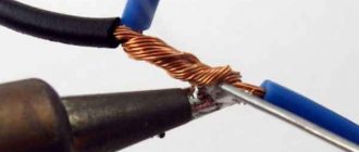
This method can be performed at home using a regular voltmeter and ammeter and a pair of suitable load resistors. As resistances, it is quite possible to use several car incandescent lamps or an improvised resistor made of nichrome wire.
Description of the method from GOST
- We discharge the battery with direct current I1= 0.2 In. At the tenth second we measure the voltage value U1 at the battery terminals.
- We increase the discharge current to the value I2=In. In the next second, we measure the value of voltage U2 at the battery terminals.
Internal resistance Rd.c., Ohm is calculated using the formula Rd.c. = (U1-U2)/(I2-I1)
- Iн – rated battery discharge current.
Circuit for measuring internal resistance using the direct current (dc) technique
The resistances R1 and R2 are selected in such a way that currents I1 and I2 of the required magnitude flow. You need to focus on the rated discharge current of the battery.
The voltmeter must be connected directly to the source poles to eliminate the influence of voltage drop on the wires.
What is Impedance?
Before exploring the different methods of measuring the internal resistance of a battery, let's examine what electrical resistance means and understand the difference between pure resistance (R) and impedance (Z). R is pure resistance and Z includes reactive elements such as coils and capacitors. Both readings are obtained in ohms, a measurement that goes back to the German physicist Georg Simon Ohm, who lived from 1798 to 1854. (One ohm produces a voltage drop of 1V with a current of 1A.) The electric conductivity is also measured in siemens (s) that is reciprocal to ohmic values.
The electrical resistance of a pure load, such as a heating element, has no reactance. Voltage and current flow in unison and there is no advancing or trailing phase. The ohmic resistance is the same with direct current (DC) and alternating current (AC). The power factor (pf) is 1, providing the most accurate metering of the power consumed.
Most electrical loads are reactive and consist of capacitive reactance (capacitor) and inductive reactance (coil). The capacitive reactance decreases with higher frequency while the inductive reactance increases. An analogy of inductive reactance is an oil damper that stiffens when applying a fast back-and-forth action.
A battery has resistance, capacitance and inductance, and the term impedance includes all three in one model. Impedance can best be illustrated with the Randles model (Figure 2) that comprises resistors R1 and R2 as well as capacitor C. The inductive reactance is commonly omitted because it plays a negligible role in a battery, especially at a low frequency.
| Figure 2: Randles model of a lead acid battery. The overall battery resistance consists of ohmic resistance, as well as inductive and capacitive reactance. The diagram and electrical values differ for every battery. R1 = Internal resistant; R2 = Charge transfer; C1 = Double layer capacitor |
Measuring the battery by resistance is almost as old as the battery itself and several methods have developed over time, all of which are still in use.
Ideal current source
The ideal current source is an active element whose current does not depend on the voltage at its terminals. It is assumed that the internal resistance of an ideal current source is infinitely large, and therefore the parameters of the external electrical circuit, on which the voltage at the source terminals depends, do not affect the source current. The symbols of an ideal current source are shown in Fig. 1
The arrow in the current source or the signs “+” and “—” indicate the positive direction of the current i(t)
or the polarity of the source, i.e. the direction of movement of positive charges.
Nowadays it is customary to denote current sources with the letter J, and the lower conventional graphic image is most often used.
Ideal current source
As the resistance of an external electrical circuit connected to an ideal
At a current source, the voltage at its terminals and, accordingly, the power developed by it increase indefinitely. Therefore, an ideal current source, as well as an ideal voltage source, is considered as a source of infinite power.
A current source of finite power is depicted as an ideal current source with a passive element connected in parallel to its terminals, which characterizes the internal parameters of the source and
Representing a theoretical concept, a current source is used in a number of cases to calculate electrical circuits.
Some semblance of a current source can be a device consisting of a battery connected in series with an additional high resistance. Another example of a current source can be a five-electrode amplifying electron tube (pentode). Having an internal resistance incommensurably greater than the resistance of the external electrical circuit, these devices deliver a current that is almost independent of changes in the external load over a wide range, and it is in this respect that they are similar to a current source.
Difficulty of use
In principle, any of the possible redox reactions can be used in batteries. But there are not so many substances capable of working in technically valuable elements. Moreover, many reactions require expensive substances.
Modern batteries have a simpler structure. Two electrodes placed in one electrolyte fill a vessel - the battery body. Such design features simplify the structure and reduce the cost of batteries.
Any galvanic cell is capable of producing direct current.
The current resistance does not allow all the ions to appear on the electrodes at the same time, so the element operates for a long time. The chemical reactions of ion formation sooner or later stop, and the element is discharged.
The current source is of great importance.
How to use a multimeter correctly: instructions for dummies
Let's look at how to measure several electrical characteristics.
Potential
Algorithm for determining voltage:
- Set the mode to ACV or DCV position in the expected interval.
- Connect the black wire to the COM connector, the red wire to the VΩmA connector.
- Connect the tips of the probes to the circuit contacts. For example, insert batteries into the holes of a socket or onto the poles.
- Take a measurement.
The number displayed on the display is the voltage value in volts. The minus sign indicates that the polarity has been reversed. If the multimeter supports the hold function, the value can be locked using the HOLD button. This is convenient for a large chain of measurements.
Current strength
This characteristic is measured only when the tester is connected in series to the circuit and the power is turned on. Most devices make it possible to determine current strength up to 10 A, since large values are rarely used in everyday life. To carry out measurements, a break is made in the circuit. Further actions according to the following scheme:
- The black probe goes into the COM socket.
- Red - into the connector up to 200 mA or 10A.
- Use the tips to gently touch the contacts.
- Read the voltage value from the display.
When working with exposed wires, you must follow safety precautions to prevent electric shock.
Resistance
This characteristic can be measured without power supply. The element being tested is simply closed between two probes. If there is no conductivity, a unit is displayed on the screen. Sequencing:
- Set Ω mode by selecting maximum range.
- Insert the probes into the appropriate connectors.
- Check the condition - short the probes to each other. A 0 or small number should appear, which must be taken into account when measuring the resistance of the circuit.
- Throw the ends of the conductors onto the contacts of the object under study.
- The resistance of the element or section of the circuit will appear on the screen.
For accurate measurements, 2-3 attempts are recommended.
Electrochemical Impedance Spectroscopy (EIS)
Research laboratories have been using EIS to evaluate battery performance for many years. The high cost of equipment, slow testing times, and the need to train skilled professionals to decipher large amounts of data have limited this technology to laboratory settings. EIS reads the values of R1, R2 and C in the Randles model (Figure 7); however, complex modeling is required to correlate data in CCA and estimate power. (See How to measure capacitance.)
| Figure 7: Spectro™ Method. R1, R2 and C are measured separately, allowing charge and power levels to be measured. Provided by Cadex |
Last update 2017-02-12
Learn what resistance readings tell about a battery.
The internal resistance provides valuable information about a battery as high reading hints at end-of-life. This is especially true with nickel-based systems. Resistance measurement is not the only performance indicator as the value between batches of lead acid batteries can vary by 5–10 percent, especially with stationary units. Because of this wide tolerance, the resistance method works best when comparing the readings of a given battery from birth to retirement. Service crews are asked to take a snapshot of each cell or monoblock at time of installation and then measure the subtle changes as the cells age.
There is a notion that internal resistance is related to capacity, but this is false. The resistance of modern lead acid and lithium-ion batteries stays flat through most of the service life. Better electrolyte additives have reduced internal corrosion issues that affect the resistance. This corrosion is also known as parasitic reactions on the electrolyte and electrodes. Figure 1 shows capacity fade with cycling in relation to the internal resistance of Li-ion cells.
| Figure 1: Relationship between capacity and resistance as part of cycling. Resistance does not reveal the state-of-health of a battery and often stays flat with use and aging. Cycle test on Li-ion batteries at 1C: Charge: 1,500mA to 4.2V, 25°C Discharge: 1,500 to 2.75V, 25°C Courtesy of Cadex |