What is rated power?
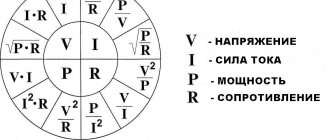
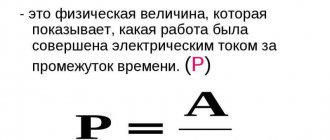
We come across the term “rated power” almost every day. Whether we choose an electric kettle or an incandescent lamp, this value is indicated everywhere. The unit of measurement is watts or kilowatts. It would seem - what could be simpler in this matter? After all, even from a school physics course, everyone knows that to determine power (P) it is enough to multiply the values of current and voltage. But what is hidden behind the words “rated power”? The term “nominal” refers to a certain value of something that does not take into account external corrective factors. Thus, the rated power is the value specified by the manufacturer, which can only be obtained with the specified design parameters. This is a general concept. In each specific case, it is necessary to take into account its specific features. Let's take an example with an incandescent lamp. Its glass bulb is marked: 230 V, 100 W. That is, 100 W can only be achieved at a voltage of 230 V. The rated power is those same 100 W. Its value decreases with decreasing voltage and increases with increasing voltage since these parameters are directly dependent on each other (P=I*U). Typically, most electrical appliances have an upper limit, usually 5-10%. In other words, operation at 230 V + 23 V = 253 V is acceptable. The lower limit may not be specified, as in the case of a lamp. More complex equipment is limited by design parameters both above and below. For example, how do we understand the term “rated engine power”? There are two equivalent definitions - one from an electrical point of view, and the other based on the calculated mechanical load on the shaft. Although they are directly related, the second one is easier to understand. We'll give both. The rating plate always shows the power value. It is numerically equal to that consumed from the electrical network at the calculated mechanical load, and the temperature of the housing must be within acceptable limits (implies long-term operation). That is, we can assume that the passport value is equal to the nominal value. If the electric drive operates in intermittent mode (duty cycle is not equal to 100%), then this correspondence is not fulfilled, since the operating time is not enough to transition to a steady state, when the increase in heating is compensated by the ambient temperature. In this case, a load diagram will be required: the rated power will be equal to the product of the passport value P and the square root of the coefficient selected from the schedule. All of the above is true for the electrical component. According to another definition, the rated power is taken to be equal to the mechanical power developed by the engine at the calculated voltage value and temperature conditions corresponding to the passport one. Thus, if the voltage (U) decreases, the torque also changes, although the shaft rotation speed may remain the same. As was said, the manufacturer includes a certain “safety margin” in the product: fluctuations in U within +-5% allow the motor to develop the design torque (with the mains frequency remaining unchanged). For frequency, this margin is only 2.5%. But the rated power of the transformer takes into account only the temperature regime. If you look at the device’s passport, it shows two temperatures: nominal and ambient. If during operation the first does not exceed its calculated value, and the second differs slightly from the passport data, then in this mode the transformer produces rated power. Any increase in electrical load causes an increase in current and temperature, so controlling the latter is sufficient. As with engines, slight excess is allowed.
UPS terms
Emergency power supply
An independent backup source of electrical energy (UPS or DGS), which, in the event of a malfunction or shutdown of the main source, provides power of the required quality and power to continue operation of the user’s equipment
Emergency (autonomous) operation mode of UPS/UPS
A mode in which power supply to equipment is provided using the energy stored in the UPS battery
Circuit breaker
A protective disconnecting component that breaks the current flow at a predetermined value
Autonomous generator
Local converter of mechanical or any other energy into electrical energy, for example, a diesel-electric generator (DGU), a wind-electric generator, etc.
Battery UPS/UPS
Energy source for UPS/UPS in case of absence or unsatisfactory quality of the mains supply. The battery voltage depends on the circuit design solutions chosen by the UPS manufacturer during its design. Typically, the battery is assembled from lead-acid sealed maintenance-free batteries; in case of special requirements, nickel-cadmium batteries are used. With a long operating time, the cost of the UPS battery begins to occupy a significant share in the cost of the system, and then a diesel generator set is used complete with a UPS for a short operating time. Battery life ranges from 3 to 10 years depending on the type of batteries used and their operating conditions
Active power (effective power)
A term used to describe the product of effective current, voltage and power factor. Expressed in Watts (W) or Kilowatts (kW). Physically represents the power actually consumed by the equipment
Active load
A load whose input power factor is "1", an example would be an incandescent light bulb or a UPS with input power factor correction. The power of such a load, measured in Watts (W), is the same as the power in Volt-Amps (VA)
Ampere (A) or kilovolt ampere (kA)
A unit of measurement of electric current. The current is equal to one Ampere when flowing through a conductor with a resistance of 1 Ohm at an applied voltage of 1 Volt
Bypass
the concept has 2 meanings:
- UPS operating mode - in which the UPS input is connected directly or through correction and filtering circuits to the UPS output. In this mode, the UPS is practically unable to influence the quality of the output voltage. The UPS is switched to bypass mode either forcibly from the UPS control , or the UPS switches to this mode on its own in the event of an overload or malfunction.
- Part of the UPS circuit - this part of the circuit ensures the bypass mode. It can be electronic (static bypass) or mechanical (maintenance bypass). The electronic bypass protects the UPS load from overload, and the equipment from power failure in the event of a UPS failure. Mechanical bypass is designed to disconnect the UPS from the network during maintenance without shutting down the protected equipment
UPS/UPS booster
A device that allows you to increase or decrease the output voltage by switching the windings of an autotransformer or by using specific circuit solutions. Used in line-interactive UPSs
Watt (W) or Kilowatt (kW)
Unit of measurement of active power. Electrically defined as the power produced by a load when a voltage of 1 Volt and a current of 1 Ampere are applied to it.
Volt (V) or Kilovolt (kV)
Voltage unit
Voltampere (VA) or Kilovoltampere (kVA)
A unit of measurement for apparent power, defined as the product of the root mean square (rms) values of voltage and current in a circuit
UPS/UPS switching time
Time for the UPS to switch to offline mode and back. For devices of the Off-line and Line-interactive class, it ranges from 5 to 20 ms, which can cause failures in the connected load. In On-line class devices, switching time does not exist (equal to zero)
Input voltage
Voltage received by the UPS from an external power supply network from a power substation or from a diesel generator set (DGS)
UPS Input Isolation Transformer (UPS)
A transformer included in the input circuit of the UPS to provide galvanic isolation of its internal components and the input electrical network. It is used to avoid short circuits in UPS circuits equipped with a non-sealed battery with liquid electrolyte, if there is a possibility of its leakage. Also used when galvanic isolation of the Bypass circuit is required
UPS/UPS input power factor
Determines how the UPS input circuits behave in relation to the input network, i.e. what load and with what power factor is the UPS for the mains or diesel generator set
UPS/UPS input rated current
RMS current consumed by the UPS at 100% load
UPS/UPS rectifier
A device that converts alternating current to direct current. In modern UPSs, the rectifier also performs the function of correcting the input power factor of the UPS
UPS/UPS Output Power Factor
Determines equipment with which power factors can be connected to a given UPS, i.e. permissible ratio of total and active power at the output of the UPS inverter. For example, an output power factor of 0.8 shows that a UPS with a total power of 100 kVA can connect equipment with an active power of no more than 80 kW with a power factor of 0.8 (the total power of the equipment will be 100 kVA). But it will no longer be possible to connect 80 kW equipment with a power factor of 0.7 to such a UPS, because its total power will be 114 kVA
UPS Output Isolation Transformer (UPS)
A transformer included in the UPS output circuit to provide galvanic isolation between the UPS and its load. Three-phase systems use a delta-star transformer. It forms the output neutral of the load, completely isolated from the input neutral of the UPS. Thus, it is possible to completely protect against interference on the input neutral, which is widespread in industrial facilities. Powerware UPSs of the PW9340, PW9370, PW9315, B4000 series are equipped with output isolation transformers
Output rated current of UPS/UPS
RMS value of current that the output circuits of the UPS can provide, provided they are 100% loaded in kVA with a normalized power factor and at the rated output voltage
UPS/UPS output voltage
The voltage provided by the UPS output circuits to power the protected equipment. Usually, the user has the opportunity to independently select the output voltage from the range - 220, 230, 240 Volts
Galvanic isolation
A circuit solution in which electrical circuits do not have a closed electrical connection between input and output. Galvanic isolation is carried out by transformers or optoelectronic devices
Generator
General name for a device for generating electrical voltage or current, or any other energy
Hertz (Hz)
see Frequency
Delta conversion
The principle of delta transformation. The principle of this conversion is that not all the energy consumed from the network is subjected to double conversion in a UPS / UPS, but only part of it (up to 15%) necessary to maintain a stable output voltage (hence the name of the principle), and this leads to reducing losses and naturally increasing efficiency. In addition, the input power factor of the UPS is significantly increased.
Acoustic decibel (dBA)
A unit of noise level measurement with a filter applied to the meter that takes into account the peculiarity of noise perception by the human hearing aid (nonlinearity of the frequency response of the ear). The noise characteristics of a UPS/UPS are usually measured in dBA
UPS/UPS input voltage range
Upper and lower input voltage thresholds at which the UPS switches to battery power. The wider this range, the less the UPS transfers to the battery, preserving its capacity and, ultimately, lifespan
UPS/UPS frequency range
Permissible deviation of the input or output frequency of the UPS / UPS from the nominal value in steady state
Diesel generator set (DGS)
A device consisting of an internal combustion engine and an electric generator used for emergency power supply of equipment
Dynamic instability of output voltage
UPS / UPS - instability of the output voltage value when the load value at the UPS output changes abruptly (usually data is given when the load power changes from 0 to 100% and from 100% to 0). The lower this value, the higher the dynamic performance of the UPS.
Frequency drift
Frequency drift is a gradual increase or decrease in its average value under constant load
Ethernet
One of the most common types of LAN
Battery capacity
The ability to accumulate and release DC electricity determines the battery life of the UPS. Measured in Ampere-hours or Watt-hours. In the case of a relatively rapid battery discharge, a more convenient concept is used - the power supplied by the battery when discharged to a certain threshold voltage value over a certain period of time.
UPS/UPS Inverter
The part of the UPS circuit that serves to convert DC battery voltage into AC voltage at the source output. In an Off-line class UPS, the inverter operates only in stand-alone UPS mode and generates a stepwise approximation of a sinusoid. In an On-line class UPS, the inverter produces an almost ideal sinusoid at the output and operates in any mode (except Bypass), receiving power from batteries at its input in autonomous mode, and in normal mode - from the input network after rectification and stabilization of the input alternating voltage
Inductance (L)
Any device whose parts include iron has a certain amount of magnetic inertia. This inertia prevents any changes in current. The characteristic of the circuit that causes this magnetic inertia is known as self-inductance. It is measured in Henry and denoted as L
Uninterruptible power supply, UPS, UPS
A device that maintains a given quality of output voltage in the presence of problems in the input voltage by using the energy of rechargeable batteries (disappearance, shape distortion, nominal deviation, etc.). Double conversion On-Line UPS class VFI-SS-111 provides protection against any power supply failures
Grounding (ground)
Potential equalization of metal surfaces of equipment with ground potential (zero) to ensure the safety of operating personnel is ensured using a grounding conductor. It also serves to suppress common-mode interference along the phase and neutral supply conductors. The rules for grounding are strictly regulated in regulatory documentation
UPS/UPS charger
The part of the UPS that ensures that the battery is kept charged. In modern UPSs, the charger operates according to a complex algorithm that ensures maximum service life of the UPS battery, subject to the recommended ambient temperature range, and fast temperature-compensated charging
kVA (kilo-volt-amperes)
The apparent power of the equipment characterizes the currents, for example, flowing through the wires between the UPS and the load. AT FULL POWER with the required margin of 10-20%, the UPS power is selected
kW (Kilowatts)
The active power of the equipment characterizes the power consumed by the load. Based on the active power, in combination with the required operating time, the capacity of the external battery of the UPS is selected
Power factor
A numerical value that determines the relationship between active power and total power consumed by the equipment. In the case of linear voltages and currents flowing in circuits, the power factor coincides with the cosine Phi (cos?). In the case of unity power factor, the current and voltage are in phase and the equipment consumes only active power - this is ideal, since a fine can be imposed on the enterprise for a low power factor. When applied to a UPS, there are input power factor and output power factor
Short circuit
A mode in which the load resistance approaches zero. The current in the circuit in this case is limited by the output resistance of the supply network and the resistance of the supply conductors. In the event of a short circuit at the UPS output, the current is limited by the UPS output inverter or its output transformer. In practice, short circuit currents are never reached because fuses or circuit breakers are installed in the circuits
Total harmonic distortion (THD or non-sinusoidal factor)
Determines the weights of higher harmonics of alternating voltage in relation to the fundamental harmonic. The lower the THD, the closer the voltage shape is to a pure sinusoid. For example: sinusoidal waveform (THD=0), the signal shape is different from sinusoidal, but the distortion is not noticeable to the eye (THD<3%), the deviation of the signal shape from sinusoidal is noticeable to the eye (THD>5%), the signal has a trapezoidal or stepped shape (THD<21%), the signal has a rectangular shape (THD=43%)
UPS/UPS input current THD
Characterizes deviations of the UPS input current shape from sinusoidal. The higher the value of this parameter, the worse it is for equipment connected to the same power supply network and the network itself, in this case electromagnetic compatibility worsens, heating of the wires increases, etc., in addition, this parameter directly affects the power reserve of the diesel generator set when coordinating its operation with the UPS
UPS/UPS output voltage THD
Characterizes deviations of the output voltage shape from sinusoidal, usually given for linear (motors, some types of lighting devices) and nonlinear loads. The higher this value, the worse the quality of the UPS output voltage.
Efficiency (efficiency) of UPS / UPS
The parameter that characterizes the power loss in the UPS is calculated as the ratio of the UPS power supplied to the load (in kW) to the UPS power consumed from the supply network (in kW). The higher this number, the lower the power loss and costs.
UPS/UPS Crest Factor
In Russian terminology, the crest factor is an indicator characterizing the ability of a UPS to power a nonlinear load that consumes pulsed current. Defined as the ratio of the maximum amplitude of the pulse current in a nonlinear load to the amplitude of the harmonic current at equivalent power consumption
Critical load
Equipment the functioning of which affects a continuous technological process or business processes, the downtime of such equipment or the disruption of the functioning of which as a result of a power failure could lead to financial or other losses
Linear load
A load in which current and voltage are related to each other by a linear law, for example: heaters, electric lamps, electric motors, etc.
Local area network, LAN
Two or more computers connected to exchange data
Power
The rate of work done or energy per unit time. Mechanical power is often measured in horsepower, while electrical power is often measured in kilowatts.
UPS/UPS power
The power that the UPS can provide to power the load. There are total (S) and active (P) powers. For most computer loads, they are related to each other by the approximate ratio S [VA] = 1.4*P [W]
Soft start UPS / UPS
An additional way to improve the compatibility of the UPS and its power supply. When switching the UPS from battery mode to input mode, there is no “impact” on it at the moment of switching, the load is transferred smoothly. The greater the time value during which the load can be transferred to the input network, the less it causes “disturbances” in it and the better for the equipment connected to this network. This property of the UPS directly affects the power reserve of the diesel generator set when coordinating its operation with the UPS
Load
Sum of power of equipment units connected to the UPS
Nonlinear load
A load (equipment) in which current and voltage are interconnected by a nonlinear law (computer, monitor...), i.e. any circuit in which semiconductor elements are present
Neutral
One of the conductors conventionally considered the return conductor in a five-wire, four-wire or three-wire alternating current system. The potential of this conductor is close to the potential of the grounding conductor. In three-phase networks (five or four wires) with a nonlinear load, even if all three phases are evenly loaded, an increased current load is placed on the neutral wire. Theoretically, the maximum current through the neutral conductor can be 1.7 times higher than the current in the phase conductor
Electrical problems
Any deviations of the supply voltage parameters from the values established by standards. The quality of electrical energy in the Russian Federation is standardized in GOST 13109-97 “Standards for the quality of electrical energy in general-purpose power supply systems” and determines the ratings and permissible deviations of the following parameters of the electrical network:
- mains supply voltage - 220 V with maximum permissible deviation ±10%;
- supply voltage frequency - 50 Hz with maximum permissible deviation ±0.4 Hz;
- THD of the supply voltage is less than 8% for a long period of time and less than 12% for a short time.
Basic power supply problems:
- complete loss of voltage in the network (network failure);
- long-term and short-term subsidence and voltage surges;
- high-voltage impulse noise;
- high frequency noise;
- frequency deviation beyond acceptable values.
The most common type of problems in big cities are long-term voltage sags, and in rural areas they are supplemented by power failures and high-voltage impulse noise.
Trickle charge
Battery charging mode in which the UPS battery is always under floating charge voltage (Floating Charge). According to Powerware ideology, this charging mode is not optimal for the battery, since it causes direct current to pass through the battery, accelerating its degradation. Powerware uses a cyclic battery charging mode - ABM (Advanced Battery Management)
Normal operation of UPS (UPS)
UPS operating mode in which the load is powered by energy drawn from the mains, and the batteries are disconnected or recharged
Rated input voltage of UPS/UPS
This is the voltage for which all UPS parameters are designed
Rated output voltage of UPS/UPS
This is the voltage that all UPS components are designed to generate.
Rated output power of UPS/UPS
The value of the total and active power of equipment that a UPS, of a certain model, can provide for an indefinitely long time with high-quality voltage normalized in all parameters
Rated input power of UPS/UPS
The value of the total and active power of the UPS, which a UPS, of a certain model, can consume from the supply network to provide power with a rated load voltage normalized in all parameters for an indefinitely long time
Rated current
The continuous current rating of an installation or apparatus determines the rms value of the alternating current or the amount of direct current in Amperes that can be maintained during normal operation without exceeding specified temperature limits.
Rated frequency of UPS/UPS
The frequency of the UPS input or output voltage for which the unit is designed. Often the UPS has the ability to operate in frequency converter mode, for example, an input frequency of 50 Hz to an output frequency of 60 or 400 Hz
Single phase load
An AC load or source, typically having three input or three output terminals, respectively. Three terminals - for connecting phase, neutral and ground conductors
Single-phase and three-phase UPS / UPS (1ph and 3ph)
UPSs according to the phase configuration of inputs and outputs differ into three types: single-phase input - single-phase output (1:1 or 1ph / 1ph), three-phase input - single-phase output (3:1 or 3ph / 1ph), three-phase input - three-phase output (3: 3 or 3ph / 3ph)
Parallel redundancy, expansion of UPS system power
A method of constructing an uninterruptible power supply (UPS) system, the purpose of which is either to increase reliability (redundancy) or to increase the total output power of the UPS (scaling). Achieved by parallel connection of several UPSs and combining their inputs and outputs. The functionality of such a system is ensured by a special phase synchronization circuit for the output voltage. In the case of hardware redundancy, if all UPSs connected in parallel are in good condition, the load is evenly distributed between them, and if one of the sources fails, it is redistributed among the working ones, and the faulty UPS is disconnected from the system. Different manufacturers have different control algorithms and protocols for exchanging information in a parallel system. For example, Powerware uses the HotSync™ control algorithm, which does not require the exchange of frequency and load information between the UPSs in the system to operate. The uniqueness of the solution lies in the fact that there is no exchange of information between UPSs, load power distribution and frequency adjustment are carried out by each UPS independently, and, consequently, the reliability of the entire system as a whole increases.
Apparent power (apparent power) (kVA, VA)
A term used when the current and voltage are in different phases or have a non-sinusoidal shape, which causes reactive (excessive) current components to flow in the circuits. As a result, they talk about apparent power and express it in Volt-amperes (VA) or Kilovolt-amperes (kVA)
Period
The time it takes for an alternating current or voltage to completely change from zero to a positive maximum, zero, a negative maximum and back to zero again. The number of cycles per second represents the frequency, the value of which is expressed in Hertz (Hz). For a network with a frequency of 50 Hz, the period is 20 ms
Alternating current
An electric current that periodically changes its direction and amplitude as it flows through a conductor or circuit. The magnitude of the alternating current increases from zero to a maximum value, then returns to zero, and then the same thing happens in the opposite direction. One complete change occurs in one period or 360 degrees. In the case of alternating current with a frequency of 50 Hertz, the direction of the current changes 50 times per second
Sequential redundancy
A method for constructing an uninterruptible power supply (UPS) system, the purpose of which is to increase the reliability of the power supply system for critical equipment by connecting several UPSs in series, one of which is the main one, and the others are backup. To connect according to this scheme, each UPS must have a separate input of the rectifier circuit and the Bypass circuit. While the main UPS powers the load, backup sources operate in idle mode, consuming minimal power. If signs of malfunction of internal components are detected, the main UPS switches to Bypass mode, and the entire load is taken over by the next backup source in the scheme, which powers the equipment through the bypass circuit of the main UPS
D.C
Electric current that flows in only one direction at a given voltage. The amount of DC current is usually constant for a particular load.
SNMP protocol
(Simple Network Management Protocol) - a protocol for monitoring the operation of network devices, defines a set of tools used by network management programs (Network Management System - NMS) to obtain information about the operation of network devices. To describe network devices, SNMP uses MIB (Management Information Bases)
TCP/IP protocol
Internet Protocol for connecting different networks
Work station
Any network computer that is not a server
Reactivity
Present when there is inductance and/or capacitance in the circuit
UPS/UPS redundancy
Methods for constructing an uninterruptible power supply system aimed at ensuring uninterrupted power supply to the protected equipment even in the event of a malfunction of the UPS or any of its functional parts. The UPS can have redundant internal units (modular UPS) or redundancy is achieved through the use of several UPSs connected in parallel or in series
Bypass mode
Only for On-line UPS of VFI class. In this mode, the load is supplied directly from the mains with filtered and surge-protected voltage. Allows you to increase reliability and avoid using a UPS with more power than necessary
Convolution (shutdown)
Curtailment of the local area network. Consists of correctly shutting down servers and workstations while saving data in running applications
Server
A networked computer that has resources that can be used by other computers and/or performs specialized functions
Network adapter
A device that allows a computer or other device to connect to a LAN
Uninterruptible power system (UPS)
Provides power supply to equipment with voltage with standardized parameters in the event of a complete absence of voltage in the supply network or an unacceptably high deviation of the mains voltage parameters from the nominal values (see “Network problems”). There are two main types of UPS: uninterruptible power supplies (UPS) and generator sets (DGU and BGU)
Star connection
Method of connecting phases in a three-phase system. A fourth or neutral conductor can be connected to the midpoint
Delta connection
A three-phase connection in which the beginning of each phase is connected to the end of the next. The load is connected to the corners of the triangle. In some cases, a center tap is made in each phase, but most often it is made in one leg, providing a four-wire connection
Root Mean Square (RMS)
Used to measure AC current and voltage. Devices that measure this value are labeled “True RMS”; cheap “Chinese” multimeters measure the root mean square value only for a sine wave; for non-sinusoidal values, they have a significant error
Lifetime
Usually this refers to the service life of the battery, which greatly depends on the ambient temperature, the number and depth of battery discharges, and the battery charging mode. In practice, for 5-year-old batteries the service life is 3-6 years, for 10-year-old batteries - 7-10 years
Stabilization (voltage, etc.)
The ability to maintain a value as close as possible to the nominal value
Static instability of UPS/UPS output voltage
The ratio of the deviation of the output voltage from the nominal value to the nominal value with slow changes in the input voltage or load on the UPS. The lower this value, the higher the quality of output voltage stabilization
Rackmount
Standardized rack for placing equipment. The most common rack with a width of 19 inches
UPS/UPS Dry Contacts
UPS interface connector contacts that physically close or open depending on the state of the UPS, i.e. change their resistance from infinity to zero. Implemented on a relay, also called AS400
Ambient temperature
The temperature of the environment in which the equipment operates, in particular the UPS or SPS. May be expressed in degrees Celsius or Fahrenheit
Temperature compensated battery charge UPS/UPS
Necessary to compensate for the influence of ambient temperature. Any change in ambient temperature in the area where the UPS batteries are located should result in a change in battery charging voltage. If this does not happen, the battery may be overcharged or undercharged.
Current (I)
The strength of the flow of electricity. Direct current flows from the negative pole to the positive pole. Alternating current changes its direction. Theoretically, when calculating current and power, the generally accepted direction is from the positive pole to the negative pole. Measured in Amperes
Three-phase
Three sine waves of voltage/current with a period of 360 degrees and an offset of 120 degrees between them. A three-phase system can be either 4- or 5-wire (3 phase conductors, one neutral and one ground)
Phase
One of the conductors in the power supply network. The potential of this conductor changes with a frequency of 50 Hz relative to the neutral conductor. In a three-phase supply network, the voltage waveform of each phase is a sinusoid shifted by 120° relative to the other phases
UPS/UPS filter
Part of the circuit that serves to suppress noise coming from the network to the UPS and from the UPS to the network. To further reduce input current distortion, an additional
THD filter
Installed in the input circuit of the UPS to reduce its influence on the voltage form in the supply network. Since the input node of any powerful UPS, built according to a double conversion (On-Line) circuit, is a rectifier, a non-linear element that consumes a large pulse current, such a UPS becomes the cause of “pollution” of the electrical network. The use of a THD filter can significantly reduce such “pollution”.
Powerful uninterruptible power systems of the Powerware 9150, Powerware 9155, Powerware 9170, Powerware 9305, Powerware 9340, Powerware 9370 series are equipped with filters that reduce the THD of the input current to 5 ... 10%.
It should be noted that all modern UPSs are equipped with input rectifiers with low input current THD and do not require additional filters. An example is the Powerware 9155, Powerware 9355, Powerware 9340, Powerware 9390 UPS series
Voltage filtering
Cleaning or highlighting the main curve, in particular, a sine wave against a background of noise and various interferences, measured in dB
Voltage form
The pattern of changes in voltage. Ideally, a sinusoidal shape, i.e. obeying the law U=Umax*Sin(?*t)
Cold start UPS/UPS
The ability of a UPS to turn on and provide power to a critical load in the absence of input voltage in the mains, receiving electricity from the battery
Voltage frequency
The number of cycles of sign change (full periods) of voltage or current in 1 second. Measured in Hertz (Hz). A voltage frequency of 50 Hz means that the voltage changes sign 50 times per second
Electromagnetic compatibility
The property of equipment not to interfere with the operation of other equipment
High Power UPS
Uninterruptible power supply capable of working with increased power. In most cases, a high-power UPS is equipped with an output isolation transformer. It forms the output neutral, eliminates even current harmonics, and balances the phases. These models work stably with any type of load.
Double conversion UPS
An uninterruptible power supply operating in non-autonomous mode using the double conversion principle. The principle of operation is double conversion of the current type. First, the input AC voltage is converted to DC, then back to AC voltage using an inverse converter (inverter). The switching time is identically zero. Double conversion UPSs have low efficiency (from 80% to 94%), which is why they have increased heat generation and noise levels. Double conversion UPSs are capable of adjusting not only voltage, but also frequency.
AC UPS
Designed to reliably protect the user's single-phase electrical equipment from any network problems, including distortion or loss of voltage in a three-phase network, as well as suppression of high-voltage pulses and high-frequency interference coming from the network.
DGS service life
This is the period of time during which the manufacturer (Cummins Inc.) undertakes to provide the consumer with the opportunity to use the diesel generator set for its intended purpose and is responsible to the consumer for significant defects that arise in the product due to the manufacturer’s fault.
UPS service life
This is the period of time during which the manufacturer (Eaton/Powerware) undertakes to provide the consumer with the opportunity to use the UPS for its intended purpose and is responsible to the consumer for significant defects that arise in the product due to his, the manufacturer's, fault.
UPS reliability (data center)
The ability of equipment to maintain over time, within established limits, the values of all parameters characterizing the ability to perform the required functions in given modes and conditions of use, maintenance, storage and transportation. In English, the term MTBF (Mean Time Between Failures) is used - the mean time between failures or time between failures, as well as MTTF (Mean Time To Failure) - the mean time to failure. It should be noted, however, that published MTBF/MTTF values are often based on the results of accelerated testing - for a limited time, allowing the identification of predominantly the proportion of manufacturing defects. In this case, the declared MTBF value speaks not so much about the reliability itself, and certainly not about durability, but about the percentage of rejected products.
A.C.
Alternating current (from “Alternating Current”). It is used when it should be indicated that the voltage or current in the device changes sign with a certain frequency, for example. "230 Volts AC". In power distribution systems d.t. frequency p.t. in most
Selecting a generator by power
When choosing a generator, the consumer pays attention to various installation parameters - weight, service life, mobility, availability of additional functionality, price, etc. But first of all, you need to choose an installation based on its power. How to correctly calculate this indicator and what to pay attention to?
To make it clearer, let's look at this situation using a simple example. Let's say we have the following household appliances: a vacuum cleaner, a heater, a freezer. The power of these household appliances is 1 kW, 2 kW and 0.3 kW, respectively. It turns out that in order to ensure the operation of these devices, we need a generator with a power of at least 3 kW. To understand this, let's understand the concept of rated power of the generator.
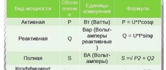
The nominal, or, as it is also called, the real power of the installation, differs significantly from the maximum. In technical documentation, manufacturers most often indicate the maximum power ratings for a given generator model. It is worth noting that with such a load the installation can operate for a very short time without critical consequences - in some cases it is seconds, sometimes 1-2 minutes. At the same time, the real or rated power is slightly lower than the maximum. To calculate it, the power factor cos φ is required. This indicator is determined by the ratio of active power to total power.
Differences
Active power is measured in kilowatts, and total or nominal power is measured in kilovolt amperes. Volt ampere with kilovolt ampere, being a power unit of current, is calculated as the product of current ampere values in an electrical circuit and the volt voltage at its ends. A watt per kilowatt is the energy accomplished per second and is equal to one joule. The measurement is carried out using the force of constant energy at a volt voltage.
You might be interested in: The design and operating principle of an incandescent lamp
Note! Only a part of the device’s power is involved at the time of work activity. The rest comes out.
How do the values differ?
Example
Let's say we have a generator with a power rating of 3 kVA and cos φ equal to 0.8. In this case, the rated power of this installation will be equal to:
3 kVA x 0.8=2.4 (kW)
Now you can understand why power can be indicated in certain units of measurement, in watts (W) or Volt Amperes (VA). Some manufacturers, in order to save the consumer from the need to carry out calculations, simply indicate in the accompanying documentation both power values - nominal and maximum. There are also options when the manufacturer indicates only one of the capacities and gives the value of the power factor. Some unscrupulous companies may hide the power factor from the consumer. This is done in order to pass off the generator as a more powerful unit than it actually is.
Power units
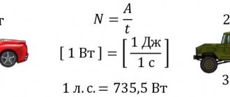
1 W (watt) - current power of 1 A (ampere) in a conductor, between the ends of which a voltage of 1 V (volt) is maintained.
A device for measuring the power of electric current is called a wattmeter. Also, the current power formula allows you to determine power using a voltmeter and ammeter.
An off-system unit of power is kW (kilowatt), GW (gigawatt), mW (milliwatt), etc. Related to this are some off-system units of work that are often used in everyday life, for example (kilowatt hour). Since 1kW = 103W, and 1h = 3600s, then
1 kWh = 103 W 3600 s = 3.6 106 W s = 3.6 106 J.
Taking into account the type of load
Household electrical appliances are characterized by two types of load:
- Active;
- Reactive.
The active (ohmic) load is consumed by devices that convert the received energy into heat. This is an electric stove, iron, hair dryer, air heaters, etc. The reactive load is consumed by other electrical appliances, which convert only a small portion of the energy into heat. The bulk of the energy consumed is used for another purpose. Examples of such appliances include a refrigerator, vacuum cleaner, TV, computer, etc.
If you need help choosing the generator power for your home, industrial workshop or any other facility, contact our specialists for qualified advice.
Converting kVA to kW and vice versa
In layman's terms, the difference between kW and kVA is that kW is useful and kVA is total power. According to the following example of converting values kVA-20%=kW and 1=0.8 kW. To convert ampere to kW, subtract twenty percent from the first value. The result will be an indicator with a small error. For example, if a household stabilizer has a power of 15, then to calculate kilowatts, you need to multiply this value by 0.8 or subtract 20% from it. Then you can recalculate everything using online converters. As a result, you need to follow a simple formula:
P=S * Cosf, where P is the active power, S is the apparent power, Cos f is the power coefficient.
Conversion formula
To reverse the action and calculate kilovolts, for example, on a 10 kilowatt portable generator, you need to divide this value by 0.8, according to the formula below:
S=P/ Cos f, where S is considered the total power, P is the active force, and Cos f is the power coefficient. More detailed background information is given in any physical textbook, including the answer to the question of how to convert the power of a 1000 kVA transformer into kW.
Formula for converting kW to kVA
It is worth noting that the most common interpretations of the power coefficient are the following values: 1 is the optimal value, 0.95 is good, 0.90 is satisfactory, 0.80 is average, 0.70 is low and 0.60 is bad. Therefore, converting the power of a 1000 kVA transformer into kilowatts is not difficult.
Power coefficient values
Answering the question what is the difference between kilowatt and kilovolt, we can say that these are two different quantities. In the first case, this is a unit of measurement for total power, and in the second, only active power. Their difference is manifested in the operation of electrical equipment, despite the possible similarity in the writing of quantities.
Car engine power calculator
Power is an important technical parameter of an internal combustion engine. It affects the dynamics of acceleration, the size of the maximum speed and the elasticity of the motor. It also affects the amount of transport tax, which almost every motorist is required to pay.
To find out the strength of your engine, you will need special formulas and calculation methods. The car engine power calculator, which is presented below in our article, can also help you.
- Calculation of engine power: methods and necessary formulas
- Calculation via torque
- What is torque
- How are engine speeds calculated?
- Calculation of power by engine volume
- Air flow calculation
- Calculation of weight and acceleration time from zero to hundreds
- Calculation of injector performance
- Horsepower calculation
- What is horsepower in a car?
Calculation of engine power: methods and necessary formulas
Engine power is the energy that is generated inside the internal combustion engine during its operation. This indicator is key for any car, and many motorists rely on it when choosing a car. It can be defined in various ways. Let's list the main methods:
- Through revolutions and torque.
- By volume of internal combustion engine.
- By air flow.
- In terms of weight and acceleration time to 100 kilometers per hour.
- According to the performance of injection nozzles.
The main unit of measurement for power is watts, but it is sometimes expressed in terms of horsepower. There is a simple relationship between these units of measurement, so if necessary, horsepower can be easily converted to watts (and vice versa).
In our article, we will look at the basic formulas for determining power, and also learn how to convert horsepower to watts.
Calculation via torque
This method of counting is the main one. To measure power, you need to know two technical parameters - torque and engine speed. Therefore, the calculation is carried out in two stages.
What is torque
Torque is the force that acts on a rigid body during rotation. The higher this indicator, the more powerful the engine of your vehicle will be. The following formula is used to calculate torque:
The formula is deciphered as follows:
- KM is torque.
- O is the total engine volume, expressed in liters.
- D is the pressure in the combustion chamber, expressed in MPa.
- 0.0126 is the correction factor.
How are engine speeds calculated?
To calculate operating power, we need not only torque, but also engine speed. In simple terms, RPM is the speed at which the engine crankshaft rotates. The relationship here is also direct - the higher the rotation speed, the more powerful and productive your car will be.
To calculate power through revolutions, use the following formula:
- KM is torque (the formula for calculating it can be found in the previous paragraph).
- RO - engine speed (expressed in revolutions per second).
- 9549 is the correction factor.
Please note that this formula is suitable for calculating the maximum engine power .
Unfortunately, during operation of the internal combustion engine, part of the power is “eaten up” by certain elements of the car (transmission, transfer case, air conditioning, and so on).
Therefore, in fact, the actual engine power indicator will be 10-15% less, depending on the type of car and the nature of its operation at the moment.
Calculation of power by engine volume
The attentive reader probably noticed that the first formula can be directly substituted into the second to simplify the calculations. The power in this case can be expressed as follows:
M = (KM x OD)/9549 = (O x D x OD)/(9549 x 0.0126) = (O x D x OD)/120.3.
The decoding of this formula will be standard:
- O - engine volume.
- D is the pressure in the combustion chamber.
- OD - revolutions.
- 120.3 is the new correction factor.
Please note that the pressure in the combustion chamber (variable D) in the case of a standard gasoline engine is usually in the range from 0.8 to 0.85 MPa . In the case of a reinforced forced engine, this figure will be 0.9 MPa , in the case of a diesel engine - from 1 to 2 MPa .
Air flow calculation
If your car is equipped with an on-board computer and auxiliary sensors, then the power can also be determined by air consumption.
