What is reactive power?
First, let's look at the concept of electrical power.
In the broadest sense of the word, this term means work performed per unit of time. In relation to electrical energy, we will slightly correct the concept of power: by electrical power we will understand a physical quantity that actually characterizes the rate of current generation or the amount of transmitted or consumed electricity per unit of time. It is clear that the work of electricity per unit time is determined by electrical power, measured in watts. The instantaneous power in a section of the circuit is found using the formula: P = U×I , where U and I are the instantaneous values of the voltage and current parameters in this section.
Strictly speaking, the above formula is valid only for direct current. However, in sinusoidal current circuits, the formula only works when the consumer load is purely active. With a resistive load, all electrical energy is spent doing useful work. Examples of resistive loads are resistive devices such as a boiler or an incandescent lamp.
If there are capacitive or inductive loads in the electrical circuit, parasitic currents appear that are not involved in performing useful work. The power of these currents is called reactive.
With inductive and capacitive loads, some of the electricity is dissipated as heat, and some prevents useful work from being done.
Devices with inductive loads include:
- electric motors;
- chokes;
- transformers;
- electromagnetic relays and other devices containing windings.
Capacitors have capacitance.
The essence of the concept
When electric current flows through a conductor, an electromagnetic field appears around it. It is formed due to moving elementary particles with a charge. A magnetic field is considered the main sign of the presence of an electric field. When one changes, the other also changes. If the current in the conductor disappears, then the electromagnetic field will still not disappear anywhere, except that it will lose its intensity.
The founder of field theory was the English physicist James Clerk Maxwell. It was he who proved the connection between these two phenomena, describing them in his work published in 1857. The scientist proved that the electric field cannot exist separately from the magnetic field. The magnitude of these fields is related to the energy contained in them. It is constantly transferred from one form to another, but does not disappear.
The electromagnetic field propagates in the form of radiation, or as scientists say - spatial disturbance. This emission travels freely in any physical environment. It is characterized by frequency, length and polarization (direction) of the wave. And also one of the parameters of radiation is the amount of energy transferred by the wave (intensity).
Numerically, intensity is defined as the average period of oscillation of a wave penetrating an area located perpendicular to it. Moreover, it is related to the energy density and the speed of wave propagation. The flow of electromagnetic energy is found taking into account the Poynting vector, which takes into account the density, intensity and field strength.
That is, mathematically, the intensity is described by the expression: I (t) = 1/T ∫ {s (t)} dt, where S (t) is the Pointing vector. In a simple understanding, its meaning is that the quantitative component of electricity changes over time, and the rate of change depends on the strength of the electric field and magnetic induction.
To designate the electrical component of the electromagnetic field, the concept of electrical power was introduced. It is understood as a physical quantity that characterizes the transfer or transformation of electrical energy.
Physical definition
The main characteristic of any electrical device is power. The transfer of electricity from a power source to a load is accompanied by the conversion of energy from one type to another. The generated electricity is transmitted through an electrical circuit (for example, a transmission line) and is partially dissipated. In other words, part of the electricity is converted into other energy: thermal, light, mechanical.
This transformation is characterized by intensity, indicating how much of it will transform into another form per unit of time. The intensity with which transformation occurs is called power.
According to the International System of Units (SI), current power is measured in watts. Its abbreviated designation in Russian is W, and in the international language it is W. In technical literature, the value itself is denoted using the Latin letter P.
The mathematical definition corresponding to the above looks like P = dW / dt, that is, it characterizes the change in energy over time. Whether it is power generated by sources or transmitted through power lines, it has the same physical meaning. Its value is calculated depending on the signal shape, that is, constant and variable components.
Since its change occurs over time, for the convenience of understanding the process, the concepts of instantaneous values were introduced. With their help, you can calculate energy for any point in time.
Instantaneous quantities
Instantaneous power is understood as the amount of energy corresponding to the product of the potential difference and current in a certain section of the circuit. Any solid physical body consists of a crystal lattice, which contains charge carriers - electrons. Their measure is the pendant. They can be either free or attached to atoms. Free particles move chaotically in the body, compensating for the energy of their movement in different directions in relation to each other.
You might be interested in The work of third-party forces in a DC circuit and sources of EMF
If an electromagnetic field is applied to a body that has free electrons, then their movement will become orderly. This movement is called current strength. The current is determined by the ratio of the number of charges passing through a conductor with a unit cross section per unit time: I = dQ/dT. Its measurement value is ampere.
To move a charge in a conductor, it is necessary to expend work, which is called voltage. That is, it is a physical quantity corresponding to the energy expended to move a charge from one point to another. The difference in energy values at these points is called the potential difference. Voltage is measured in volts. And its value can be calculated using the formula: U = A/q.
When moving in the body of a conductor, electrons encounter various impurities and defects in the crystal lattice. As a result, part of their charge is transferred to these structures, that is, power is actually taken away. The captured energy is partially converted into heat and light. The number of certain fluctuations (inhomogeneities) along the current path was called resistance, the value of reverse conductivity. In accordance with SI, it is denoted by the letter R and measured in ohms.
The instantaneous dependence of all three quantities on each other was established by experimental physicist Simon Ohm. According to his law, the current strength is directly proportional to the potential difference and inversely proportional to the resistance in a section of the circuit. That is, it is equal to: I = U/R.
Physics of the process
When we are dealing with DC circuits, there is no need to talk about reactive power. In such circuits, the values of instantaneous and total power are the same. The exception is the moments of switching on and off capacitive and inductive loads.
A similar situation occurs in the presence of purely active resistances in sinusoidal circuits. However, if devices with inductive or capacitive reactances are included in such an electrical circuit, a phase shift in current and voltage occurs.
In this case, a phase lag of the current is observed on inductances, and on capacitive elements the phase of the current shifts so that the current leads the voltage. Due to the violation of the current harmonics, the total power is decomposed into two components. Capacitive and inductive components are called reactive and useless. The second component consists of active capacities.
The phase shift angle is used when calculating the values of active and reactive capacitive or inductive powers. If the angle φ = 0, which occurs with resistive loads, then there is no reactive component.
Important to remember:
- the resistor consumes exclusively active power, which is released in the form of heat and light;
- inductors provoke the formation of a reactive component and return it in the form of magnetic fields;
- Capacitive elements (capacitors) cause the appearance of reactance.
Occurrence of reactive power
Let's say the circuit contains a DC power supply and an ideal inductance. Turning on the circuit generates a transient process. The voltage tends to reach the nominal value; the growth is actively hampered by the inductance’s own flux linkage. Each turn of the wire is bent in a circular path. The resulting magnetic field will cross the adjacent segment. If the turns are located one after the other, the nature of the interaction will increase. This is called intrinsic flux linkage.
The nature of the process is as follows: the induced EMF prevents changes in the field. The current tries to grow rapidly, the flux linkage pulls back. Instead of a step we see a smoothed protrusion. The energy of the magnetic field is spent to interfere with the process that created it. The case of reactive power occurrence. The phase differs from the beneficial one and is harmful. Ideal: the direction of the vector is perpendicular to the active component. It is assumed that the wire resistance is zero (a fantastic scenario).
When the circuit is turned off, the process will be repeated in reverse order. The current tends to instantly drop to zero; energy is stored in the magnetic field. If the inductance disappears, the transition will take place suddenly, flux linkage gives the process a different coloring:
- A decrease in current causes a decrease in the magnetic field strength.
- The effect produced induces the back-EMF of the turns.
- As a result, after the power source is turned off, the current continues to exist, gradually attenuating.
Reactive power is a certain link of inertia, constantly lagging and interfering. The first question is: why then are inductors needed? Oh, they have plenty of useful qualities. Benefit makes you put up with reactive power. A common positive effect is the operation of electric motors. Energy transfer occurs through magnetic flux. Between the turns of one coil, as shown above. A permanent magnet, a choke, and everything capable of being captured by an induction vector are subject to interaction.
The cases cannot be called comprehensive in a descriptive sense. Sometimes clutch flow is used in the form shown as an example. The principle is used by ballasts of gas-discharge lamps. The inductor is equipped with a myriad of turns: turning off the voltage does not cause a smooth decrease in current, but a surge of large amplitude of the opposite polarity. The inductance is great: the response is truly amazing. Exceeds the original 230 volts by an order of magnitude. It is enough for a spark to appear and the light bulb to light up.
Reactive power and capacitors
Reactive power is stored by magnetic field energy by inductances. What about the capacitor? Acts as a source of the reactive component. Let us supplement the review with the theory of vector addition. The average reader will understand. Oscillatory processes are often used in the physics of electrical networks. The well-known 220 volts (now accepted 230) in a 50 Hz outlet. A sine wave whose amplitude is 315 volts. When analyzing circuits, it is convenient to represent them as a clockwise rotating vector.
Graphical circuit analysis
The calculation is simplified and the engineering representation of reactive power can be clarified. The current phase angle is considered equal to zero and is plotted to the right along the abscissa axis. The reactive energy of the inductance is in phase with the UL voltage and is 90 degrees ahead of the current. Ideal case. Practitioners have to take into account the winding resistance. Part of the power will be reactive to inductance. The angle between the projections is important. The value is called power factor. What does this mean in practice? Before answering the question, let's consider the concept of a resistance triangle.
Power triangle and cos φ
For clarity, let us depict the total power and its components in the form of vectors. Let us denote the total power vector by the symbol S, and assign the symbols P and Q to the vectors of the active and reactive components, respectively. Since the vector S is the sum of the current components, then, according to the rule of vector addition, a power triangle is formed.
Power factor
Applying the Pythagorean theorem, we calculate the modulus of the vector S:
From here you can find the reactive component:
Reactive component
We have already mentioned above that reactive power depends on the phase shift, and therefore on the angle of this shift. It is convenient to express this dependence in terms of cos φ. By definition, cos φ = P/S . This value is called the power factor and is designated Pf. Thus, Pf = cos φ = P/S.
Power factor, that is, cos φ, is a very important characteristic that allows you to evaluate the efficiency of current operation. This value is in the range from 0 to 1.
If the phase shift angle takes a zero value, then cos φ = 1, which means that P = S, that is, the total power consists only of active power, and there is no reactance. When the phases are shifted by an angle π/2, cos φ = 0, which means that only reactive currents dominate in the circuit (in practice, this situation does not arise).
From this we can conclude: the closer to 1 the coefficient Pf, the more efficiently the current is used. For example, for synchronous generators a coefficient of 0.75 to 0.85 is considered acceptable.
§57. AC Power and Power Factor
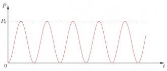
Instantaneous power value. In a circuit containing active, inductive and capacitive resistance, in which the current I and voltage u are generally shifted in phase by a certain angle ?, the instantaneous value of power p is equal to the product of the instantaneous values of current i and voltage u. The instantaneous power curve p can be obtained by multiplying the instantaneous values of current i and voltage u at different angles ?t (Fig. 199, a. From this figure it is clear that at some moments in time, when the current and voltage are directed towards each other, the power has a negative value . The occurrence of negative power values in an electrical circuit is harmful. This means that during such periods of time the receiver returns part of the received electricity back to the source; as a result, the power transmitted from the source to the receiver decreases. Obviously, the greater the phase shift angle ?, the greater the time during which part of the electricity returns back to the source, and the greater the energy and power returned back.
Active and reactive power. Instantaneous power can be presented as the sum of two components 1 and 2 (Fig. 199,b). Component 1 corresponds to a change in power in a circuit with active resistance (see Fig. 175,b).
Its average value, which is called active power,
P = UI cos ? (75)
It represents the average power that flows from the source to electrical installations at alternating current.
Component 2 changes similar to the change in power in a circuit with reactance (inductive or capacitive, see Fig. 179, a and b). Its average value is zero, therefore, to evaluate this component, use its amplitude value, which is called reactive power:
Q = UI sin ? (76)
Considering the power curves (see Fig. 199, b), it can be established that only active power can ensure the conversion of electrical energy into other types of energy in the receiver. This power has a positive sign throughout the entire period, i.e. the corresponding electrical energy 2, called active, continuously moves from source 1 to receiver 4 (Fig. 200, a). Reactive power cannot create any useful work, since its average value over one period is zero. As can be seen from Fig. 199, b, this power becomes either positive or negative, i.e. the corresponding electrical energy, 3, called reactive,
Rice. 199. Dependence of instantaneous power p (a) and its components (b) on the angle ?t
Rice. 200. Diagram illustrating the transfer of electrical energy between a source and a receiver containing active and reactive resistance, in the absence of a compensator (a) and in its presence (b): 1 - source; 2.3 - conventional images of active and reactive energy; 4 - receiver; 5 - compensator
continuously circulates through the electrical circuit from the source of electrical energy 1 to the receiver 4 and back (see Fig. 200, a).
The occurrence of reactive power in an alternating current circuit is possible only when energy storage devices, such as an inductor or a capacitor, are included in this circuit. In the first case, the electrical energy coming from the source is accumulated in the electromagnetic field of the inductor and then released back; in the second case, it accumulates in the electric field of the capacitor and then returns back to the source. The constant circulation of reactive power from source to receivers loads alternating current generators and electrical networks with reactive currents that do not create useful work, and thus does not make it possible to use them for their intended purpose for generating and transmitting active power to consumers. Therefore, in production conditions, they try to reduce as much as possible the reactive power consumed by electrical installations.
Full power. Sources of alternating current electrical energy (generators and transformers) are designed for a certain rated current Inom and a certain rated voltage Unom, which depend on the design of the machine, the size of its main parts, etc. It is impossible to significantly increase the rated current or rated voltage, as this can lead to unacceptable heating of the machine windings or breakdown of their insulation. Therefore, each generator or transformer can deliver for a long time, without the danger of an accident, only a very certain power, equal to the product of its rated current and rated voltage. The product of effective values of current and voltage is called apparent power,
S = UI
Therefore, apparent power represents the highest value of active power for a given current and voltage. It characterizes the maximum power that can be obtained from an alternating current source, provided that there is no phase shift between the current passing through it and the voltage. Apparent power is measured in volt-amperes (V*A) or kilovolt-amperes (kV*A).
The relationship between the powers P, Q and S can be determined from the vector voltage diagram (Fig. 201, a). If we multiply all sides of triangle ABC by current I, we obtain a power triangle A'B'C' (Fig. 201,b), the sides of which are equal to P, Q and S. From the power triangle we have:
S = ?(P2 + Q2)
From this expression it follows that for a given apparent power S (i.e. voltage U and current I), the greater the reactive power Q that passes through the alternator or transformer, the less active power P it can deliver to the receiver. In other words, reactive power does not allow the full design power of alternating current sources to be fully used to generate useful electrical energy. The same applies to electrical networks. The current I = ?(Ia2+Ip2), which can be safely passed through a given electrical network, is determined mainly by the cross-section of its wires. Therefore, if part of the current Iр passing through the network (see Fig. 194, b) is used to create reactive power, then the active current Ia must be reduced, ensuring the creation of active power that can be passed through this network.
Rice. 201. Voltage vector diagram (a) and power triangle (b) for an alternating current circuit
If active power P is given, then with an increase in reactive power Q, the reactive current Iр and the total current I passing through the wires of alternating current generators, transformers, electrical networks and electrical energy receivers will increase. At the same time, power losses ?P = I2Rpp in the active resistance Rpp of these wires also increase.
Thus, the useless circulation of electrical energy between the alternating current source and the receiver, due to the presence of reactances in it, also requires the expenditure of a certain amount of energy, which is lost in the wires of the entire electrical circuit.
Power factor. From formula (75) it follows that the active power P depends not only on the current I and voltage U, but also on the value of cos?, called the power factor:
cos? = P/(UI) = P/S = P/?(P2 + Q2)
By cos value? one can judge how a given receiver or electrical circuit uses the source power. The greater cos?, the less sin?, therefore, according to formulas (75) and (76) for given U and I, i.e. S, the greater the active and less reactive power supplied by the source. As cos increases? and constant active power P supplied to the receiver, the current in the circuit I = P/(U cos?) decreases. At the same time, power losses ?P = I2Rпp in the wires are reduced and the possibility of additional loading of the source and electrical network is provided, i.e., their better use. If the receiver is powered from a source with a constant load current, then an increase in cos? leads to an increase in the active power P used by the receiver. When cos?=1, reactive power is zero, and all power supplied by the source is active. Therefore, all enterprises and all sectors of the national economy strive to increase the power factor in every possible way and bring it, if possible, to unity.
Power factor values for AC electrical installations vary. Electric lamps have mainly active resistance, so when they are turned on, there is practically no phase shift between current and voltage. Therefore, for a lighting load the power factor can be considered equal to unity. The power factor for AC motors depends on the load. At the rated design load of the engine cos? = 0.8-0.9, and even higher for large engines. When the engines are underloaded, their power factor decreases sharply (at idle, cos ? = 0.25-0.3).
Improved power factor. Cos? increase in various ways. The main one is the inclusion of special devices called compensators in parallel with the electrical energy receivers. As the latter, capacitor banks (static compensators) are most often used, but synchronous electric machines (rotating compensators) can also be used.
Way to increase cos? using a static compensator (Fig. 202, a) is called phase shift compensation, or reactive power compensation. In the absence of a compensator, a current i1 flows from the source to the receiver, containing active and inductive reactances, which lags behind the voltage and by a certain phase angle ?1. When the compensator Xc is turned on, a current ic passes through it, leading the voltage by 90°. As can be seen from the vector diagram (Fig. 202, b), in this case, current i1 will flow in the source circuit and its phase shift angle will be ? relative to voltage will also be less than ?1.
To fully compensate for the phase shift angle ?, i.e., to obtain cos? =1 and the minimum current value Imin, it is necessary that the compensator current Ic is equal to the reactive component I1p = I1 sin ?1 of the current I1. When compensator 5 is turned on (see Fig. 200, b), source 1 and the electrical network are unloaded from reactive energy 3, since it already circulates through the “receiver - compensator” circuit. Thanks to this, a significant increase in the use of alternating current generators and electrical networks and a reduction in energy losses arising from the useless circulation of reactive energy between source 1 and receiver 4 are achieved.
Rice. 202. Diagram illustrating the method of increasing cos? using a compensator (a), and vector diagram (b)
In this case, the generator acts as a generator of reactive energy, since the currents Iin the capacitor and I1p in the inductor (see, Fig. 202, b) are directed towards each other (the first leads the voltage in phase by 90°, the second lags behind it by 90° ), as a result of which turning on the compensator reduces the total reactive current Iр and the phase shift between the current I and voltage U. With proper selection of the reactive power of the compensator, it can be achieved that all reactive energy 3 (see Fig. 200, b) entering the receiver 4, will circulate within the “receiver-compensator” circuit, and the generator and network will not participate in its transmission. Under these conditions, only active power 2 will be transmitted from source 1 to receiver 4, i.e. cos ? will be equal to one.
In most cases, for economic reasons, electrical installations carry out incomplete compensation of the phase shift angle and are limited to the cos value? = 0.95.
Full power
According to established practice, consumers do not pay for the useful power, which is directly used in the household, but for the full power, which is supplied by the supplier. These indicators are distinguished by units of measurement - total power is measured in volt-amperes (VA), and useful power is measured in kilowatts. Active and reactive electricity is used by all electrical appliances powered from the network.
Reactive electricity concept
This type of electricity is inherent in circuits that contain reactive elements. Reactive electricity is the portion of the total incoming power that is not spent on useful work.
In DC circuits there is no concept of reactive power. In AC circuits, a reactive component occurs only when an inductive or capacitive load is present. In this case, there is a mismatch between the phase of the current and the phase of the voltage. This phase shift between voltage and current is indicated by the symbol “φ”.
With an inductive load in the circuit, a phase lag is observed, and with a capacitive load, it is advanced. Therefore, only part of the total power reaches the consumer, and the main losses occur due to useless heating of devices and instruments during operation.
Power losses occur due to the presence of inductive coils and capacitors in electrical devices. Because of them, electricity accumulates in the circuit for some time. After this, the stored energy is fed back into the circuit. Devices whose power consumption includes a reactive component of electricity include portable power tools, electric motors and various household appliances. This value is calculated taking into account a special power factor, which is designated as cos φ.
Electrical Energy Measurement
Based on the expression P= U*I, we can conclude that energy can be measured using instruments designed to measure voltage and current. You will need to obtain the data using an ammeter and voltmeter, and then, substituting them in the formula, calculate the power value. The essence of the measurement is that a voltmeter is simultaneously connected in parallel to the circuit, and an ammeter is connected in parallel to the open circuit. This method is called indirect, and the use of two instruments reduces the accuracy of the result obtained.
Therefore, special testers were developed designed for direct energy measurement - wattmeters. This kind of meters can be used in single-phase circuits of both direct and alternating current. But wattmeters are divided into two categories:
- Digital - their circuitry is based on a microprocessor unit that analyzes the received signal and, using complex algorithms, calculates the result, which is displayed on the device screen in digital form. Their measurement error is no more than 0.1.
- Analog - using electrodynamic and ferrodynamic measuring heads. They are made in the form of coils that deflect the arrow. The deviation scale is graduated in watts. Depending on the influence of the field, the arrow deviates by the measured amount. The first type of device has an accuracy class of about 0.1-0.5, and the second - 1.5-2.
Analog devices are hardly used anywhere anymore, mainly for finding the power of devices connected to an industrial network with a frequency of 50 Hz. At DC, their results are mediocre, since the measuring coils are affected by the hysteresis of the cores (saturation effect).
Varmeters make up a separate subgroup of testers. These are special meters designed to calculate reactive power. And also for the indirect method, an electrical measuring device called a phase meter is used. Using it, you can find the phase angle of the signal, that is, actually determine the power factor.
Reactive power calculation
The power factor ranges from 0.5 to 0.9; The exact value of this parameter can be found in the electrical device data sheet. The apparent power must be determined as the active power divided by the factor.
For example, if the passport of an electric drill indicates a power of 600 W and a value of 0.6, then the total power consumed by the device will be equal to 600/06, that is, 1000 VA. In the absence of passports for calculating the total power of the device, the coefficient can be taken equal to 0.7.
Since one of the main tasks of existing power supply systems is to deliver useful power to the end user, reactive power losses are considered a negative factor, and an increase in this indicator calls into question the efficiency of the electrical circuit as a whole. The balance of active and reactive power in a circuit can be visualized in the form of this funny picture:
Reactive coefficient
In another way, it is called the power factor and is a dimensionless quantity introduced to calculate the reactive component. Scientifically speaking, it shows how much the phase of the alternating current flowing through the load shifts from the voltage that appears across it. Numerically, it is taken to be equal to the cosine of the shift. Mathematically, this shift is interpreted as the cosine of the angle between the vector values of current and voltage.
In simple words, the power factor, denoted φ, indicates that part of the consumed electricity that is converted into useful work. For example, with cos φ = 0.9, ninety percent of the total energy will be spent on performing a useful action, and the remaining ten will be considered losses. Therefore, if the passport for any device indicates that the power of the product is 500 W, and cos φ = 0.5, then its total energy consumption will be 500/0.5 = 250 VA.
That is, the coefficient φ is found from the ratio of the energy consumed by the device to the total power value. Often, the equipment passport also indicates the component φ (the nature of the load). It can be resistive-capacitive or resistive-inductive. In this case, the coefficient itself is respectively leading or lagging.
If the voltage in the circuit changes according to a sinusoidal law, and the current according to a non-sinusoidal law, then the load will not have any reactive component, and the coefficient is assumed to be equal to the main wave (first harmonic). Non-sinusoidal refers to distortions of the electrical signal associated with harmonics that dominate the fundamental frequency.
In mathematics, the formula for finding the power factor is the expression: cos φ= P/S. Therefore, the higher its value, the less energy the device consumes from the network. There are various ways to raise the value of cos φ, even to a maximum value of one, called correction. The most effective is to add a complex electronic unit to the circuit, placed at the input of the device.
Differences
The difference between the values is that the active power characteristic shows the efficiency of the devices, and the reactive one is the transfer of this efficiency. The difference is also observed in definition, symbol, formula and significance.
You might be interested in Features of kW and kVA units of measurement
Note! As for the meaning, the second is needed only to control the voltage created from the first value and overcome power fluctuations.
The meaning of reactive load
Any reactive load creates a time shift between the phases of current and voltage. This value is measured in degrees. The most visual is the vector representation of electrical parameters. If you connect an inductance, the voltage will lead the current. The angle between them is denoted in formulas by the letter “ϕ” (“Phi” in Greek).
Time and vector diagrams show how the main parameters change when connecting inductive (capacitive) elements
The picture shows that when a capacitive load is connected, the vectors “swap” places. Under ideal conditions, the shift between vectors is 90°. In reality, one should take into account the influence of electrical resistance of the circuit and imperfect designs. Taking into account the characteristics of the elements, it should be recalled that in the inductance (capacitance), while maintaining the parameters of the power source, the current (voltage) changes smoothly, respectively.
Why is the voltage in the network variable?
To explain the present situation, we need to make a brief excursion into history. Electricity has been known to man for hundreds (according to some sources, thousands of years). However, the truly massive use of this energy began relatively recently - at the end of the 19th century. It was then (1879) that Edison patented the first functional device that helped solve lighting problems. To power light bulbs, he began installing DC networks.
Ten years later, Tesla created alternating current generators. After fierce competition, it was his method of transmitting energy over distances that won. This result was achieved more by market methods than by careful comparison of consumer characteristics.
For your information. The New York City Subway still operates with DC power.
Sources
- https://www.asutpp.ru/reaktivnaya-moschnost.html
- https://VashTehnik.ru/enciklopediya/reaktivnaya-moshhnost.html
- https://FB.ru/article/191380/chto-takoe-aktivnaya-i-reaktivnaya-elektroenergiya
- https://amperof.ru/teoriya/reaktivnaya-moshhnost.html
- https://rusenergetics.ru/ustroistvo/reaktivnaya-moschnost
Formula for the general case
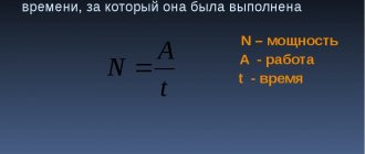
Since voltage is work, multiplying it by the number of charges transferred will give you the energy expended to move particles from one edge of the conductor to the other. Energy, in a general sense, is work per unit of time. Therefore, we can write the following expression Pab = A/dt, where:
- dt is the time interval during which all free charges were transferred;
- A - the work itself.
The formula for current power for one charge can be written P = U/dt, and based on it for all charges as Pab = q*U/dt, where q is the number of charges passing from one point (a) to another (b) over a period of time dt.
Based on the definition given to the current strength, it is practically a charge. In the case of time variation, the current can be described by the expression I = q/dt. Then, based on this formula, the statement that q = I*dt will be true. If we substitute the resulting formula instead of q into the expression describing the power, we get Pab = U* (I*dt/dt) = U*I.
If the change time is infinitely small, then we can assume that the voltage and current practically do not change. As a result, the instantaneous electrical power will be equal to P (t) = u (t)*i (t). As can be seen from the formula, the power value for any point in time will be directly proportional to the instantaneous values of the current and potential difference. Moreover, if the circuit is not ideal, then it contains a certain resistance. Using Ohm's law for a section of a circuit, the formula for finding instantaneous power can be rewritten as P (t) = i (t)2*R = u (t)2/R.
Power is simultaneously associated with several quantities at once and corresponds to the total work expended on moving a certain number of coulombs per unit of time (one second). From the definition it follows that the same power value can be obtained in different ways, for example, by reducing the current but increasing the voltage. This approach is used when transmitting energy over long distances. For this purpose, transformers are used to step down and step up the current.