Option 1
This protection is the simplest and differs from similar ones in that it does not use any transistors or microcircuits. Relays, diode isolation - that’s all its components.
The scheme works as follows. The minus in the circuit is common, so the positive circuit will be considered.
If there is no battery connected to the input, the relay is in the open state. When the battery is connected, the plus is supplied through the diode VD2 to the relay winding, as a result of which the relay contact closes and the main charging current flows to the battery.
At the same time, the green LED indicator lights up, indicating that the connection is correct.
And if you now remove the battery, then there will be voltage at the output of the circuit, since the current from the charger will continue to flow through the VD2 diode to the relay winding.
If the connection polarity is reversed, the VD2 diode will be locked and no power will be supplied to the relay winding. The relay will not work.
In this case, the red LED will light up, which is intentionally connected incorrectly. It will indicate that the polarity of the battery connection is incorrect.
Diode VD1 protects the circuit from self-induction that occurs when the relay is turned off.
If such protection is implemented in a car battery charger , it is worth taking a 12 V relay. The permissible relay current depends only on the power of the charger . On average, it is worth using a 15-20 A relay.
Reverse polarity protection device for charger. | Master Vintik. Everything with your own hands!
A simple circuit for protecting the battery and charger from polarity reversal
But when searching the Internet for the required scheme, I did not find anything similar. And before that I saw it a year ago. I drew a diagram from memory and am ready to share it with you.
This device is needed to protect your battery and charging from damage, preventing you from mixing up the terminals and will save you from many problems.
Here is a diagram of a polarity reversal device for relay chargers.
- Elements:
- R1 = 510 Rel2 = 12V (Any 12V 10-15A, removed from a former UPS for a computer, can be used with a car)
- VD1-3= 1N4007 (or similar).
Although VD3 is not required, you can use a jumper instead. VD1 from the self-induction of the relay coil.
This is how the device works. When you connect a battery, the remaining charge in it passes through the relay and closes the contacts, thereby supplying current from the charger to the battery.
If you connect the wires to the battery incorrectly, then VD2 will not allow electricity to pass through the relay and charging will not start. And instead of charging, the LED will light up, indicating that the charging is not connected correctly.
Here is a reverse polarity protection device for a PCB charger.
Reverse polarity protection device seal for the charger.
- You can use this link to download the Sprint-Layout 5.0 reverse polarity protection device seal for the charger
- Source: malmon.ru
- Charger diagram for IPod, IPhone
- Homemade automatic battery charger
- More information about charging and discharging a car battery
The circuit proposed below on the MC34063A allows you to charge your iPod without connecting it to a computer. Using a computer's USB port to charge the battery is not always practical. For example, there is no computer at hand or there is no need to turn it on because it is charging. Cell phone chargers for iPods and MP3 players are available, but they are expensive and you need to have separate charging options at home and in the car. Read more…
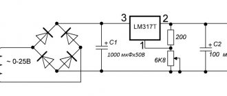
A simple charger with current regulation and charge control for a car battery
The battery is one of the important elements in a car. It needs to be monitored and charged on time, especially in winter, and also when the car has not been used for a long time. For this you need a charger. You can buy it, or you can assemble it from inexpensive parts, which will cost much less than a store-bought one, but in terms of characteristics and reliability it is superior to some copies currently sold. After remaking a whole bunch of chargers, I finally assembled a fairly simple charger with current regulation and automatic charge control. Read more…
A car battery ( AK battery ) is one of the most important parts of a car . The battery provides electricity to: electric lamps in the headlights, instrument panel and interior lighting, the vehicle's electronic ignition system, fuel pump, car radio and other vehicle components, as well as the most consumed load source - the starter when starting the engine. Normal operation of all vehicle components is possible only with a properly used battery. It must be serviced and charged on time. Read more…
Popularity: 17,828 views.
Source: https://www.MasterVintik.ru/ustrojstvo-zashhity-ot-perepolyusovki-dlya-zaryadnogo-ustrojstva/
Option 2
This scheme still has no analogues in many respects. It simultaneously protects against power reversal and short circuit.
The operating principle of this scheme is as follows. During normal operation, the plus from the power source through the LED and resistor R9 opens the field-effect transistor, and the minus through the open junction of the “field switch” goes to the output of the circuit to the battery.
When a polarity reversal or short circuit occurs, the current in the circuit increases sharply, resulting in a voltage drop across the “field switch” and across the shunt. This voltage drop is enough to trigger the low-power transistor VT2. Opening, the latter closes the field-effect transistor, closing the gate to ground. At the same time, the LED lights up, since power for it is provided by the open junction of transistor VT2.
Due to its high response speed, this circuit is guaranteed to protect the charger from any output problem.
The circuit is very reliable in operation and can remain in a protected state indefinitely.
Examples of circuits and their descriptions
Circuits for protecting the power supply from output short circuit or overload are built on different element bases. They can be divided according to the type of element used as a key.
On a bipolar transistor
Overcurrent protection circuit on a bipolar transistor.
Simple short circuit protection can be assembled using a bipolar transistor. A resistance of 0.5 Ohm was used as a measuring shunt.
In the initial position, transistor T1 is open (through resistor R1). Transistor T2 is off. When the current through the shunt increases and the voltage on it reaches sufficient to open the transistor T2 , the voltage at the base of T1 drops almost to zero, it closes, interrupting the current. At the same time, the LED lights up, signaling a short circuit. When the current decreases below the limit, the circuit returns to its original position.
When the power supply voltage is above 25 and below 8 volts, you may have to select resistor R1 so that the key transistor is reliably open. Resistor R3 can be used ready-made ceramic or made from nichrome.
Ceramic 10-watt 0.5 ohm resistor.
The triggering current is set by selecting the shunt resistance - the higher it is, the lower the current the protection will operate. Also, the response current is affected by the resistance of the resistor R2 and the gain of the transistor T2 , which can be used as any low-power device of the npn structure. The operating current is limited by the highest collector current of the switch, which can be a powerful NPN transistor.
| Transistor type | Maximum collector current, A |
| KT819 | 10 |
| KT729A(B) | 30(20) |
| 2N5490 | 7 |
| 2N6129 | 7 |
| 2N6288 | 7 |
| BD291 | 6 |
| BD709 | 6 |
The inherent drawback of such a circuit solution is that the full load current flows through the switch (and the short-circuit current until the transistor closes). Therefore, the key element must be installed on a radiator of appropriate size.
On a field effect transistor
This drawback can be somewhat mitigated by using a field-effect transistor as a switch. Its resistance in the open state is noticeably lower, which means the power dissipated on it is also less. And the load current is limited to a lesser extent.
Short circuit protection on a field-effect transistor.
Here the switch is located in the negative output voltage bus. In the initial position, the field-effect transistor is open by the voltage supplied through the LED. The current in this circuit is very small, the LED does not light. Transistor T2 is closed. As the current consumption increases, the voltage on the shunt R1 begins to increase, when it increases to the opening level T2 , the switch T1 will close, and the current through the LED will increase, indicating that the protection is activated. The trigger level is adjusted by selecting the shunt resistance.
The protection current can also be adjusted by changing resistance R4 . If you install a potentiometer instead, you can make adjustable current protection. You cannot use a variable or tuning element as R1
Transistor T2 is any low-power one. T1 must be designed for full load current. You can use transistors from the table or others suitable for current and voltage.
| Transistor type | Maximum drain current, A |
| IRFZ40 | 50 |
| IRFZ44 | 41-55 (depending on version) |
| IRFZ46 | 46-55 (depending on version) |
| IRFZ48 | 61-72 (depending on version) |
If the operating current exceeds 8..10 amperes, the key must be installed on the radiator.
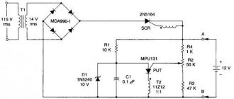
On a thyristor
If there is no powerful transistor, protection can be assembled using a thyristor. Features of this scheme:
- the second sign of a short circuit is used - a decrease in voltage;
- The protection operates in a rectified (pulsating) voltage circuit (without smoothing capacitors).
Overcurrent protection circuit on a thyristor.
The second feature is due to the fact that the thyristor turns off during the next decrease in voltage to zero at the end of the half-cycle. With constant voltage, it will not close until the load is removed (or the power supply is turned off). Therefore, the scope of application of this circuit is limited to transformer chargers (batteries do not need voltage smoothing).
During operation of the circuit, at the beginning of each half-cycle, the voltage across the divider P1R4 increases, transistor T1 opens, supplying voltage to the control electrode of the thyristor. VS1 also opens, passing half a sine wave into the load. When the voltage drops, the transistor turns off. The thyristor also closes, because at the moment it passes through zero, the current through it drops to a level less than the holding current. In the new half-period everything repeats itself again. If, as a result of a short circuit, the output voltage decreases, the transistor will not be able to open, and the thyristor will not open either . When the current drops to the nominal level, the output voltage will be restored and the thyristor will open again. The operating current (more precisely, voltage) is set by potentiometer P1 .
Option 3
This is a particularly simple circuit, which can hardly even be called a circuit, since it uses only 2 components. This is a powerful diode and fuse. This option is quite viable and is even used on an industrial scale.
Power from the charger is supplied to the battery through the fuse. The fuse is selected based on the maximum charging current. For example, if the current is 10 A, then a 12-15 A fuse is needed.
The diode is connected in parallel and is closed during normal operation. But if the polarity is reversed, the diode will open and a short circuit will occur.
And the fuse is the weak link in this circuit, which will burn out at the same moment. After this you will have to change it.
The diode should be selected according to the datasheet based on the fact that its maximum short-term current was several times greater than the fuse combustion current.
This scheme does not provide 100% protection, since there have been cases when the charger burned out faster than the fuse.
All types of protection in computer power supplies
Greetings, friends!
During the operation of any electronic device, “swirls” can occur, which, in the absence of insurance, can damage it, and in the case of a power supply in a PC, several components in addition. The topic of today's publication is protection in power supplies, with a description of all the necessary options. So, let's begin. p, blockquote 1,0,0,0,0 —>
Bottom line
From an efficiency point of view, the first scheme is better than the others. But from the point of view of versatility and speed of response, the best option is scheme 2. Well, the third option is often used on an industrial scale. This type of protection can be seen, for example, on any car radio.
All circuits, except the last one, have a self-healing function, that is, operation will be restored as soon as the short circuit is removed or the polarity of the battery connection is changed.
Author: Eduard Orlov –
Attached files:
A simple reverse polarity protection circuit
Well, as promised, the second article is devoted to the polarity reversal protection system, which has found quite wide application in industrial and home-made chargers. This option was chosen as particularly simple and can be repeated even by a person who has nothing to do with electronics.
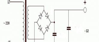
To implement such a protection circuit, you only need a diode - just one diode, which will be installed in the forward direction on the positive bus of the charger.
Such a system is just so simple that to modify the charger, it is not at all necessary to disassemble it. To implement this idea, we use the most important function of a semiconductor diode - in the forward direction the diode is open, but if it is connected in the reverse direction, it will be locked.
Consequently, if you suddenly confuse the polarity, then the current simply will not flow, no pops, heating or other smoke effects.
But as we know, when the voltage flows through the junction of the rectifier diode, then at the output of the latter there will be a voltage drop in the region of 0.7 Volts, precisely in order for the drop to be minimal, we will use SCHOTTTKY diodes (with a Schottky barrier) - there is a drop on it voltage is around 0.3-0.4 Volts. The only drawback of such protection is that a fairly large current will flow through the diode, which leads to heating of the diode.
To do this, the diode must be installed on the heat sink. High current Schottky diodes can be found in computer power supplies. The diodes in the indicated blocks are a three-terminal diode assembly; each assembly contains two diodes with a common cathode. You need to select diodes with a current of at least 15 Amps per diode. In computer units there may be diodes with a current of up to 2x30 Amperes.
- First you need to install a diode on the heat sink, then parallelize the anodes of the diodes, so we connected both diodes in parallel.
- Author; AKA KASYAN
- .
Source: https://xn—-7sbbil6bsrpx.xn--p1ai/prostaya-sxema-zashhity-ot-perepolyusovki.html
Correct selection of wire and cable cross-sections
The main measure for protection against short circuits is the selection of a suitable cross-section for cables and conductors. The conditions of future operation, as well as the equipment that is planned to be connected, should also be taken into account.
The ability of conductors to operate under continuous load conditions depends entirely on the cross-sectional area of the conductors, measured in mm2. There are special tables that facilitate the choice, which detail the performance of conductors in accordance with the load, taking into account the electrical parameters of the network.
All conductors are selected with some margin, so in most home networks 1.5 mm2 conductors are used for lighting, and 2.5 mm2 for the socket group. If necessary, individual electrical wiring calculations are performed to eliminate overheating and other negative consequences.
The material of the conductors should also be taken into account. For example, the resistance of aluminum is approximately 1.8 times higher than that of copper. That is, with the same current strength and cross-section, the aluminum core will heat up 2 times faster. Therefore, in modern wiring diagrams, cable and wire products only with copper conductors are used. Aluminum wires are used only in high-power electrical installations and for transmitting electricity through power lines.
Protection of circuits from power reverse polarity using an N-channel MOSFET
n-channel MOSFET + 7.2…15V zener diode + resistor of a couple of tens of kilo-ohms = SAFETY
[Read in English]
The task seems to be trivial. And why would anyone ever need to protect any electronic products from power supply reverse polarity?
Alas, an insidious case has a thousand and one ways to slip a minus instead of a plus onto a device that you spent many days assembling and debugging, and now it just started working.
I will give just a few examples of potential killers of electronic breadboards, and finished products too:
- Universal power supplies with their universal plugs, which can be connected either with a plus on the internal contact or with a minus.
- Small power supplies (such boxes on the power plug) - they are all produced with a plus on the central contact, aren’t they? NO!
- Any type of connector for power supply without a hard mechanical “key”. For example, convenient and cheap computer “jumpers” with a pitch of 2.54mm. Or screw clamps.
- How do you like this scenario: the day before yesterday there were only black and blue wires at hand. Today I was sure that the “minus” is the blue wire. Bang - that's a mistake. At first I wanted to use black and red.
- Yes, just if you have a bad day - mix up a couple of wires, or plug them in the other way around simply because you were holding the board upside down...
There will always be people (I know at least two such peppers) who, looking straight into the eyes, will firmly and categorically declare that they will never do such a stupid thing as reversing the polarity of the power source! God is their judge. Maybe after they themselves assemble and debug several original designs of their own design, they will become wiser. In the meantime, I won't argue. I'll just tell you what I use myself.
Life stories
I was still quite young when I had to resolder 25 out of 27 cases. Luckily, these were good old DIP microcircuits. Since then, I almost always place a protective diode next to the power connector.
By the way, the topic of protection against incorrect power polarity is relevant not only at the prototyping stage. Just recently I witnessed the heroic efforts of a friend to restore a giant laser cutter.
The cause of the breakdown was a would-be technician who mixed up the power wires of the sensor/stabilizer for the vertical movement of the cutting head. Surprisingly, the circuit itself seems to have survived (it was, after all, protected by a diode in parallel).
But everything burned out completely afterwards: amplifiers, some kind of logic, control of servos...
Protection diode in series with load
This is perhaps the simplest and safest option for protecting the load from power supply reverse polarity. There is only one bad thing: the voltage drop across the diode. Depending on which diode is used, it can drop from about 0.2V (Schottky) and up to 0.7...1V - on conventional rectifier diodes with a pn junction. Such losses may be unacceptable in the case of a battery-powered or stabilized power supply. Also, at relatively high current consumption, power losses on the diode can be very undesirable.
Protection diode in parallel with load
With this type of protection there are no losses during normal operation. Unfortunately, in the event of a polarity reversal, the power supply runs the risk of breaking. And if the power source turns out to be too strong, the diode will burn out first, followed by the entire circuit it protects.
In my practice, I sometimes used this type of reverse polarity protection, especially when I was sure that the power source had overcurrent protection. However, one day I earned very clear prints on my burnt fingers when I touched the radiator of the voltage stabilizer, which was trying to fight against a thick Schottky diode.
Source: https://MyElectrons.ru/mosfet-reversed-protection/