The term limit switch is nothing more than a common abbreviation for “limit switch”. In it, the contacts are closed without fixation by a movable rod - this is convenient for monitoring the position of moving elements. Limit switches of various types are installed in cars on the doors or in the trunk; they control the position of the brake pedal and handbrake lever.
What is a limit switch
A limit switch is a limit switch, which is installed in the control system for generating a signal that gives permission for further operation of the circuit. It usually has several pairs of contacts (open and closed). But there are also contactless limit switches, which consist of an infrared LED and a photocell located opposite each other.
Device
The limit switch consists of movable contact elements and fixed ones. It has a metal case in which the entire mechanism is installed. The switch structure is shown in the diagram below.
Mechanical limit switch (structural part)
The main parameter of limit switches is the free play of the switch rod, which, depending on the modification, is 0.5-2.7 mm. The operating stroke of switches is measured in millimeters. Therefore, the devices can be used using an additional lever, which is equipped with a small roller.
Principle of operation
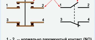
Let's look at the principle of operation using the example of a car limit switch circuit. When any door acts mechanically on the roller of the movable rod, the contact closes, as a result of which the interior lamp lights up. The diodes on the electrical circuit are installed against reverse currents.
Schematic diagram of turning on the car lamp through limit switches
Application
Limit switches are used:
- in furniture products;
- in the automotive industry;
- in everyday life and household appliances;
- in production.
Options for installing alarms on Focus 3
BP-03 is a module that facilitates the installation of remote or automatic engine starting systems on vehicles equipped with an RFID (radio frequency identification) system. The RFID system is used on most modern cars. A transponder is built into the car's standard ignition key, the code of which is polled when the engine is started with the key.
To remove the Ford Focus 3 under-torpedo, remove the left dashboard trim (on the latches). Next, unscrew 1 self-tapping screw securing the torpedo and remove it (on the latches). We disassemble the Ford Focus 3 steering column housing (1 screw and latches). You must first remove the plug covering the key slot. To access the Ford Focus 3 VCM unit, remove the glove compartment. To do this, remove the right torpedo trim and unscrew 1 screw behind it. Next, unscrew the 2 screws at the top of the glove compartment. Then remove the bottom trim of the VCM unit (2 clips) and unscrew the 2 screws securing the glove compartment under it.
We install an antenna with a built-in shock and tilt sensor on the windshield of a Ford Focus 3, an LED on the right pillar. We install the service button in any convenient place.
Install under the hood
We install a siren and an engine temperature sensor under the hood of a Ford Focus 3. We route the wires through the standard seal on the right side of the engine shield. To install the siren, it is necessary to dismantle the right headlight unit (fastened with 2 screws).
Basic connections on Ford Focus 3
Most connections are made on the connectors of the VSM unit. In connector C1 we connect the CAN alarm bus. We connect it in connector C3. In connector C3 of the BCM unit we connect the ignition circuit, accessories, alternative control of central locking and alarm.
To turn off the car lights and radio after remote start, connect in connector C2 to the driver's door limit switch wire according to Scheme 1 and perform additional programming. channel according to paragraph 16 of the installation map. To simulate pressing the clutch pedal (on a Ford Focus 3 with a manual transmission), we make connections in the harness behind the BCM unit according to Scheme 2 and perform additional programming. channel according to paragraph 16 of the installation map. In a thick harness above the BCM block we connect the starter control of the Ford Focus 3. In connector C5 of the BCM block we connect the power supply to the Starline alarm. To bypass the standard immobilizer, we put the frame of the BP-03 bypass module on the ignition switch
Kinds
Limit switches are divided into the following types:
- mechanical;
- contactless;
- reed switches;
- ultrasonic;
- capacitive;
- sensory (optical);
- inductive.
Mechanical
Mechanical limit switches are the main type of switches in construction, as well as manufacturing and metallurgy. The presence of rubber seals on the contact group protects the devices from dust and dirt.
Contacts of mechanical limit switches can withstand current up to 16 amperes.
Mechanical switches are:
- push-button;
- lever;
- roller
Contactless
Contactless limit switches operate on a transistor switch, which has low resistance. The advantages of such devices include the absence of burning of contacts, as well as compactness.
Wireless switch
Ultrasonic
Ultrasonic circuit breakers are used as volume and motion sensors and are based on special quartz elements. The devices can withstand small loads in the circuit, such as from a curtain drive motor or low-voltage equipment.
Ultrasonic limit switch
Capacitive
Such switches operate in the event of a change in electrical capacitance created by man. When approaching the device, an electrical capacitance appears, which activates the multivibrator device located in the end switch. The closer a person comes, the greater the capacitance and the lower the pulse frequency. The basis of the mechanism is the capacitor plate.
The video below discusses capacitive limit switches. Filmed by chipdip channel.
Touch (optical)
The touch switch device has an infrared LED and a phototransistor. The diode, controlling the supplied pulse, allows the circuit to open the phototransistor. Such devices can be widely used on CNC.
Inductive
Inductive limit switches operate within a specified range of the electromagnetic field. The sensor, which has left the magnetic field zone, sends a pulse to turn on the device.
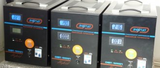
Ford Focus Security Alarm System
The system prevents thieves from trying to open the interior doors, trunk doors, hood, or remove the car radio.
The system is activated when the vehicle is locked. Turn the key all the way to the lock position and hold it in this position for one second.
Automatic activation delay.
The 20-second delay for activation of the security alarm begins to take effect from the moment all doors of the cabin, luggage compartment and hood are closed.
In case of unauthorized opening of the passenger compartment door, luggage compartment or hood, a warning signal sounds within 30 seconds. In addition, the hazard warning lights flash for five minutes.
Rice. 1.23. Alarm Trigger
The alarm goes off again whenever you try to start the engine or remove the car radio.
Rice. 1.24. Disabling the alarm
The security alarm system can be deactivated at any time by opening the lock of one of the front doors (even if the alarm is triggered).
The tailgate alarm system is deactivated when the tailgate is unlocked using the key or remote control. After closing the luggage compartment, the system will be activated again.
Security alarm with internal sensors
This system protects against unauthorized entry attempts by monitoring any movements occurring inside the Ford Focus.
Rice. 1.25. Security alarm sensors
The security alarm system with internal sensors is activated when the double locking function is activated.
Source
How to connect a limit switch
Before connecting the wires of devices, it is necessary to turn off the electricity by making a switch in the panel. Limit switch installation requires careful adjustment of the response.
To install and connect the device, you need to fix the door using four self-tapping screws so that when closed it presses on the limit switch key, and when open the button is released. Connect the electrical circuits of the switch through the terminal block to a current of 220 V.
The limit switch in the electrical circuit should be the last element before the supply wire.
For the front door
The limit switch on the front door is designed to ensure the functioning of the alarm system and activate the light in the apartment. It is more advisable to install contactless sensors, since they take up little space and are quite reliable in operation.
Before installation, the position of the door and the limit switch should be taken into account. To connect the electrical circuit device, it must be done on a fireproof base for fire protection purposes. Installation and adjustment of the switch should be done with a certified tool.
For wardrobe
The purpose of installing limit switches is to provide automatic lighting when the door is opened. First you need to lay electrical wiring to the cabinet. At the ends of sliding doors, it is required to install a door mechanical switch with a voltage of 220 volts. All wires must be laid in protected trays. Then the installation of the lamp and end strips are marked. After installation, the wires are connected and the operation of the limit switches is adjusted.
For sliding doors
For sliding doors, the installation of a limit switch is similar to that for furniture, but an ultrasonic sensor should be used.
For swing doors
For swing doors you need to use a mechanical push-button switch type 4313WD. Wires to the installation site are laid in trays. Setting up the operation of the switch with your own hands must be done carefully without damaging it, since the working stroke of the rod is 3.5 mm.
For gates
Roller mechanical limit switches are used to automatically open and close gates. Installation is possible only on sliding gates, since they have less play in the mechanical part than swing gates. At the ends of the gate it is necessary to install end gates, which will be connected to the opening drive motor and to the starter.
When installing switch devices on gates, the conductors are supplied to the electric motor in a corrugated pipe, and the switch is installed in a moisture-resistant housing.
For auto
The installation of limit switches in the car is necessary for the functioning of the alarm and lighting. A simple push-button switch is used on the hood and trunk doors. For interior doors - contactless. After connecting the limit switches for the car, you should adjust the sensitivity of the security system.
Loading …
Trunk limit switch
Standardly, a limit switch is installed in the trunk to activate the backlight in it; on cars with a standard alarm system, it also serves to control opening during active security. The limit switch can also be used by the standard central locking, blocking locking if the trunk is not slammed shut.
If we are talking about a cheap car with a minimum configuration, then you will have to connect the trunk limit switch yourself when installing the alarm. It’s easiest for owners of those cars where more expensive equipment includes a standard trunk alarm switch: as with doors, here it is enough to install the original part in the designated place. Otherwise, alas, you will have to drill a hole and install a universal one. Increasingly, the switch is not installed as a separate part in the trunk, but is built into the lock itself, as is the case with the doors.
Sometimes this leads to serious problems: for example, on the Renault Koleos, a failure of the trunk locking mechanism has become a “trademark disease”, and in the author’s practice, the “anti-record” is only a week after purchasing a new car. The lock, not locking, did not allow the built-in limit switch to operate, and this, as on other cars on similar platforms, blocked the locking of the central locking as a whole; due to the non-locking trunk, the owner could not lock the doors. In such cases, it was necessary to tightly block the trunk lock in a locked state until a new one arrived for a warranty replacement.
Video “Design of limit switches”
The video shows the design of limit switches. Filmed by chipdip channel.
Limit switches, end caps, limit or limit switches are the name given to a device for limiting the movement of a mechanism. They have special requirements for setting up the response. If used incorrectly (positioned in the electrical circuit), an accident may occur - the moving mechanism may break.
According to the principle of operation, it resembles a regular switch, only it does not work manually by directly pressing a key at will, but in special situations - if necessary, prevent further movement, limit it within acceptable limits.
Car alarm connection points for Ford Focus 2003, automatic transmission, SE package
Author Dragon
Ignition switch: +12V – red ACC – can not be connected Ignition – green/yellow Starter – gray/black
Connections on the BCM behind the glove compartment: Ground - black in the lower connector Opening the central locking (-) - black/yellow in the lower connector Closing the central locking (-) - black/red in the lower connector Left turn (+) - blue in the lower connector Right turn (+) – gray in the lower connector Trunk opening (-) – white in the upper connector Doors (put a diode in the gap of each wire, otherwise it will work when the car falls asleep): driver’s side – black/yellow, 2nd connector from the bottom, front passenger’s side – black/blue, 2- 2nd connector from the top, right rear – black/green, bottom connector, rear – black/orange, 2nd connector from the bottom Trunk – black/yellow in the driver’s sill (put a diode in the gap, otherwise it will trigger when the car falls asleep, if you don’t turn off the interior light)
Brake - on a frog
Engine control - solder to the battery lamp on the instrument panel.
PS the SL A91 injector is twisted.
Design
Looking at the photo of the limit switch, you can see that it consists of 2 or 3 main parts:
- Dielectric or current-conducting housing (depending on purpose and design).
- A moving mechanical part that responds to pressure. Contactless and electromagnetic ones do not have it. This part is missing from their design.
- A group of normally open/closed contacts that control movement or provide a signal.
It resembles a box of small or even miniature sizes with a moving part in the form of a button, wheel or lever.
Photo gallery
The main limit switches are shown in the photo.
Lever mechanical switch
Push Button Switch Proximity Sensor
Roller switch
Principle of operation
The limit switch works in different ways: to supply or cut off voltage. This can be either a direct mechanical effect - push, touch, pressing, or the effect of electromagnetic fields, ultrasound or infrared radiation on special elements included in the design of the switch.
Sensory ones, for example, react to an object entering the radiation spectrum of rays, capacitive ones - to the approach of a person, mechanical ones - only to direct physical impact.
Regardless of the functional features, a group of contacts that control the required range of motion is always activated.
At the same time, it is important to correctly configure and install the limit switch so that it does not start prematurely, does not miss a signal, or breaks when a working mechanism “runs into” it.
Limit switches and their purpose, where they are located in different cars
People who had to deal with the process of independently installing an alarm on a car definitely had to deal with the word limit switch. The instructions say that certain wires must be connected to it. This detail is present on absolutely every old or new car, on the doors and hood of the Grant, Niva, Kalina, Skoda, Logan, Chevrolet, Lanos, Octavia, Sprinter and other vehicles. The operating principle of limit switches is very simple, and the devices themselves are quite small in size, inexpensive, and very easy to connect. They are necessary so that you can correctly open the doors, the hood, use the lighting, and for other purposes that involve the process of enabling or disabling functions.
Classification
Limit switches are divided into types and groups. The requirements for their type and configuration are determined by the scope of their application and purpose.
There are such groups of limit switches:
- Mechanical or contact. Triggering occurs when there is direct action on a pin, button, wheel or lever. A control or warning signal is issued. These also include microswitches. Their serious drawback is burning and sticking of contacts when switched on and off repeatedly. For long-term use, without frequent repairs, their design includes arc arrester chambers.
- Pneumatic. They react to pressure in the system and stop the supply of air or any gas.
- Reed switches (electromagnetic). Activated when approaching a certain point in space. Tuned to a magnet included in the moving mechanism.
- Automotive. Used in signaling and lighting circuits. Can be classified as mechanical, since the operating principle is the same.
- Contactless. They are triggered when any object approaches a certain area.
- Spindle. They limit the movement of the mechanism and are often used as a limit switch. Can be used where the shaft rotates at low speed.
Disassembling the interior
Before you begin installing the main elements of the alarm system, prepare a place for them by performing the following work:
- Remove the lower trim of the instrument panel, first dismantling the left trim.
- Then remove the part, having previously unscrewed the fastener.
- Remove the plug from the ignition switch slot and disassemble the steering shaft casing.
- Remove the right instrument panel trim.
- Unscrew the screws securing the upper shelf of the glove box and remove the lower cover of the module control unit (BCM).
- Then they unscrew the glove box fastening and remove it, gaining full access to the module control unit.
Brief characteristics of some subspecies
The design of mechanical limit switches is determined by their scope of application. Most often this is:
- Construction;
- Mechanical engineering;
- Metallurgy.
- Various production purposes requiring automatic control.
They are mainly manufactured in the following types:
- Roller
- Lever;
- Float;
- Push-button.
Microswitches
Microswitches are a type of mechanical limit switches. They are mainly used in electronics and household appliances. But you can use them effectively at home: place them on the door so that when you open it, the light comes on or the hood turns on.
They require special care in setting up the response, since the stroke of their moving part is calculated in millimeters.
Proximity switches
Contactless switches are a more advanced device, the operation of which involves transistor switches with low resistance. When the electrical circuit breaks, the contacts do not burn.
Contactless switches have their own variety:
Ultrasonic
Used as volume and motion sensors. The design contains special sound quartz elements.
Capacitive
React to the approach of a human body. Based on interaction with him.
Touch (optical)
The design includes a special infrared LED and phototransistor. Works in any lighting. When the LED beam is interrupted, the photocell is triggered, and the working mechanism is turned off and on.
Inductive
Reacts to electromagnetic fields when approaching or moving away. Triggers when the settings are satisfied: the mechanism enters the impact zone or goes beyond it.
Based on contactless communication devices, various useful, highly sensitive sensors are manufactured, which are widely used in the process of automation of production processes. Control and dosage of liquid and bulk materials is the main area of their application.
It is important before directly installing the limit switch (regardless of its type) to turn off the voltage and de-energize the power circuit. The connection diagram itself is usually drawn on the device body and will not cause any difficulties.
To understand where the limit switch needs to be installed, you need to carefully study the features of the mechanism whose operation needs to be controlled.
Before purchasing a device and all its components, you should definitely consult with a specialist to understand which type or model is best suited for specific purposes.
In order not to overpay or buy something that is not needed, it is important to understand why the limit switch is purchased, what it will limit, which device to turn on or off. The right choice and proper connection are the key to long-term work!
Installation of hood lock StarLine L10
A reinforced hood lock is a mandatory item in the anti-theft protection program for Ford Focus vehicles. Many thefts were committed due to poor security of the engine compartment. And without installing a hood lock, the mechanical gearbox lock from Garant would also be useless - access to the engine compartment of the Focus allows you to quickly and easily “bypass” it.
During the installation of the lock, a special reinforced bracket was used.
What does the marking say?
Contactless switches are supplied to the market by various manufacturers. Among them are Western, domestic and Chinese companies
When purchasing, it is important to pay special attention to the quality of the units and the reputation of the manufacturer.
Due to the seriousness of the regulated processes, which are controlled by various modifications of sensors, you should only choose products that have accompanying documentation - instructions with installation diagrams, operating conditions and a list of technical parameters.
On the body of the device itself, manufacturers indicate its characteristics in the form of a set of letters and numbers - mark
Among these designations, some important information is encrypted, which is used when choosing the right model. Not all indicators can fit on a small area of the switch
The rest that are important to the consumer are contained in the user manual
Not all indicators can fit on a small area of the switch. The rest that are important to the consumer are contained in the user manual.
If the model you like does not come with instructions, then you should not buy it - it may be a fake. Moreover, some of the necessary parameters will remain unknown, and you cannot take the seller’s word for it.
All manufacturers are required to provide technical specifications to the end consumer. This requirement is prescribed by part 5-2 of GOST on low-voltage non-contact equipment mentioned above
Each company that produces switching devices for electrical circuit control has developed its own designation system. Its decoding is given in the catalog, which also contains the range of products offered.
An example of product labeling from the company AS Energia. The remaining parameters of the models are located in the instructions supplied with the kit.
The need for marking did not arise by chance - there is a wide variety of switches. In addition, they can be classified according to various principles.
For example, depending on the function performed during switching, devices are divided into the following categories:
- switching on (NO) – A;
- shutdown (NF) – B;
- switching – C;
- programmable option – P;
- other – S.
Depending on the installation method, sensors can be recessed, non-recessed, and others.
Sometimes manufacturers prefer to indicate a long code that describes the maximum parameters of the product, including the location of the sensitive element, the presence of an indication, climate control, etc.
If the company uses the marking principle recommended by GOST, then the inscription on the switch will, for example, look like this:
U3 A30 A D2
Where:
- U – ultrasonic method of detecting an irritant. The rest correspond to other Latin letters: I – inductive, C – capacitive, D, R and T – direct, reflective and barrier photoelectric, respectively;
- 3 – installation method is different;
- A30 – shape and diameter, which in this case means cylindrical with a thread with a diameter of 30 mm;
- A – element switching function, which means switching on (NO);
- D – number of wires for direct or alternating current output, which corresponds to two connectors for direct current;
- 2 – plug-in connection method.
In total, there are 4 combination options, among which one corresponds to ribbon wires, two is considered above, three corresponds to a clamp, and four corresponds to another method.
In modifications that require the presence of a wire, the manufacturer puts the characteristics on a label that is attached directly to the cable. It may also indicate the degree of protection, recommended voltage, etc.
Among the conscientious manufacturers are ZAO Sensor/Sesor, the German company Fotoelektrik Pauly, NPK TEKO, PKF STRAUS, ZAO Meander, the companies OWEN and SKB IS, NPP PRISMA from Yekaterinburg and others.
Many of them offer the service of manufacturing VBs with the parameters required by the consumer - to order.
We also recommend reading our other article, where we described in detail the different types of light switches. Read on for more details.
Car alarm connection points for Ford Focus 2006-2009
At the ignition switch we take the power wires. 12 Volts - red Ignition - green/yellowStarter - gray/red ACC - yellow
We connect to the dimensions on the light switch to the orange/black (in some to orange/yellow) wire (positive polarity)
The fuel pump can be found in the right threshold - green/orange.
Stop - green/white on the “frog” brake pedal.
The central locking control and door limit switches are located on the fuse block at the bottom of the passenger's feet. (In some cars, the central locking is installed in the driver's door - green/h and blue/h). Central locking (controlled by minus) - black/orange and black/green in the orange connector. When you search, close all the doors, otherwise the locks will not close. Door switches (positive) - black (driver's), black (rear left), black (rear right) and black (front right) in the same orange connector where the tsz. Look with a voltmeter, not a probe. The probe will not show a “plus” when the door is opened (at least the light bulb one). The trunk limit switch is in the same place as all the others and is also positive - black/cr.
If there is a hood switch on the car, then you can take it in the adjacent blue connector - h/w. By the way, he is also positive.
To control the engine, it is better to take a signal from an injector (any). Right wire in the direction of travel. You can try charging - the pink wire on the generator. But it takes a long time for 12 volts to appear on this wire. Therefore, autorun often does not work correctly. In terms of noise (or voltage), it works, but when the stove is fully turned on (motor at maximum), it again does not work correctly (in the case of Sherkhans, it does not work 100% correctly).
If the low beam is turned on when you turn on the ignition, then (to prevent this from happening) cut the thin side and the thin side on the headlight switch.
| Chain | Color | Location |
| + 12V | Red (thick) | In the harness to the fuse box, green large size. |
| ACC | Yellow | Egnition lock |
| IGN1 | Green/yellow | Egnition lock |
| SARTER | Grey/black | Horizontal harness behind the glove compartment (you can also block the starter there.) |
| Turns | Blue/white Blue/red | In the harness to the fuse box, green large size. |
| Handbrake (-) | Black/red | Horizontal harness behind the glove compartment. |
| Central lock (-) | Black/green | Harness for the fuse box, small orange size. |
| Black/orange | ||
| Trunk limit (+) | Black/red | |
| Left front door switch (+) | Black/yellow | |
| Left rear door switch (+) | Black/orange | |
| Right front door switch (+) | Black/blue | |
| Right rear door switch (+) | Black/green | |
| Open trunk (-) | Black/yellow | |
| Gasoline pump | Green/orange | On the right threshold. |
| Engine monitoring | Nozzle. | |
| Immo crawler StarLine BP-03. The alarm unit is conveniently located under the radio. (To remove the radio, you need special keys.) There is no point in opening the trunk with the key fob. When you open it, it still won’t open smoothly; you have to open it smoothly with your hand, but it’s heavy. Therefore, we connect all the limit switches of the doors and trunk through 5 diodes and send them to the alarm system, to the positive input of the doors. Moreover, the alarm does not have a positive trunk input. If the low beam turns on when you turn on the ignition, then to prevent this, cut the green/red thin, green/yellow thin on the sidelight switch. |
5.1. Installation of car alarm components
We install the LED indicator in the right rack
Windshield antenna
We remove the alarm unit under the dashboard. Siren and limit switch under the hood.
We mount the shock sensor above the glove compartment
5.2. Connecting circuits
All connections are made on the BCM unit (under the glove compartment).
General view of BCM
Power +12 - large green connector, red wire
Ignition (+) - large blue connector, light green/yellow wire
Starter (+) - horizontal harness behind the glove compartment, gray/black wire
Turn signals (+) - large green connector, blue and blue/orange wires
Door switches (+) - small orange connector: black/yellow, black/orange, black/blue, black/green
Connect limit switches via diodes
Please note: there are two wires black/orange and black/green, determine the ones you need!!! Trunk switch (+) - small orange connector, black/red
Trunk switch (+) - small orange connector, black/red
Central locking (-) - central locking control is connected in a small orange connector - black/orange and black/green
Valet button
Transition from the passenger compartment to the engine compartment
Alarm connection
The connection is based on the wiring diagram. If the Lada Kalina limit switches are installed incorrectly to the alarm system, it will not work normally and the car will be left unprotected.
Connection procedure using the StarLine E90 alarm system as an example:
- Driver's door. Connect the limit switch to the brown-red wire.
- Front passenger door. Connect the switch to the brown-red wire.
- Left rear door. Connect to the black and white cable.
- Right rear door. Connect to the black and white wire.
The door switches are connected in the left kick panel and the right threshold. The kick panel is where all the elements of the audio system are installed.
Kalina door limit switches are connected in the same way in the Pandora security and anti-theft system.