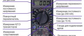
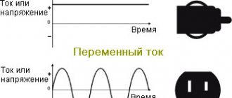
The invention of electricity brought humanity to a new frontier of development. Technological progress relied on two directions of movement using electricity. In one case, direct current was used, in the second - alternating current. The introduction of electricity sources and power consumers resulted in a hundred-year war between adherents of the two types of energy. In the end, those who promoted the idea of widespread use of its variable form won.
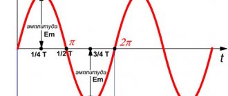
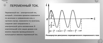
Sine wave of alternating electricity in the coordinate system
General concept of alternating current
Unlike electrons constantly moving in one direction, alternating current changes both direction and value several times per unit of time. Changes occur according to a harmonic law. If you observe a similar signal using an oscilloscope, you can see a picture in the form of a sine wave.
Relative to the ordinate axis OY, the current changes its direction from positive to negative and does this periodically. Therefore, its instantaneous value in the first position is considered positive, in the second - negative.
Important! Since alternating current is an algebraic quantity, we can talk about its sign of charge only for a specific instantaneous value, depending on the direction in which it flows at that moment.
Signal on the oscilloscope screen
Free electromagnetic oscillations. Oscillatory circuit
Electromagnetic oscillations are periodic changes in charge, current and voltage that occur in an electrical circuit. The simplest system for observing electromagnetic oscillations is an oscillatory circuit.
An oscillatory circuit is a closed circuit formed by a capacitor and a coil connected in series.
The coil resistance \( R \) is zero.
If you charge the capacitor to the voltage \( U_m \), then at the initial moment of time \( t_1=0 \), the voltage on the capacitor will be equal to \( U_m \). The charge of the capacitor at this moment in time will be equal to \( q_m=CU_m \). The current strength is zero.
The total energy of the system will be equal to the energy of the electric field:
The capacitor begins to discharge, and current begins to flow through the coil. Due to self-induction in the coil, the capacitor discharges gradually.
The current reaches its maximum value \( I_m \) at time \( t_2=T/4 \). The charge on the capacitor at this moment is zero, the voltage on the capacitor is zero.
The total energy of the system at this moment in time is equal to the energy of the magnetic field:
At the next moment of time, the current flows in the same direction, gradually (due to the phenomenon of self-induction) decreasing to zero. The capacitor is recharged. The charges of the plates have charges opposite in sign to the original ones.
At the moment of time \( t_3=T/2 \) the charge of the capacitor is \( q_m \), the voltage is \( U_m \), the current strength is zero.
The total energy of the system is equal to the energy of the electric field of the capacitor.
The capacitor then discharges again, but the current through the coil flows in the opposite direction.
At the moment of time \( t_4=3T/4 \) the current strength in the coil reaches its maximum value, the voltage on the capacitor and its charge are equal to zero. From this moment, the current in the coil begins to decrease, but not immediately (the phenomenon of self-induction). The energy of the magnetic field is converted into the energy of the electric field. The capacitor begins to charge, and after some time its charge is equal to the original one, and the current strength becomes equal to zero.
After a time equal to the period \( T \), the system returns to its initial state. One complete oscillation has occurred, then the process is repeated.
Important! The oscillations occurring in the oscillatory circuit are free. They are accomplished without any external influence - only due to the energy stored in the circuit.
In the circuit, the energy of the electric field of the capacitor is converted into the energy of the magnetic field of the coil and vice versa. At any arbitrary moment in time, the total energy in the circuit is equal to:
where \( i, u, q \) – instantaneous values of current, voltage, charge at any time.
These oscillations are damped. The amplitude of oscillations gradually decreases due to the electrical resistance of the conductors.
Periodic alternating current
One that, while changing, manages to return to its original value at equal time intervals and at the same time goes through the entire cycle of its transformations, is called periodic. It can be traced on a sinusoid displayed on the oscilloscope screen.
Period and amplitude of sinusoidal oscillation
Resonance frequency: formula
It can be seen that at regular intervals the graph repeats without changes. These intervals are designated by the letter T and are called periods. The frequency with which a certain number of similar periods fits into a unit of time is the frequency of an alternating current.
It can be calculated using the AC frequency formula:
f = 1/T,
Where:
- f – frequency, Hz;
- T – period, s.
Frequency is equal to the number of cycles per second and has a unit of 1 hertz (Hz).
Attention! The SI unit of frequency is named after Heinrich Hertz. 1 hertz (Hz, Hz) = 1 s-1. Multiple and submultiple units, expressed by standard SI prefixes, are applicable to it.
Frequency standards
In order to ensure coordination of the operation of sources of alternating electricity, transmission systems, reception and operation of electrical consumers, frequency standards are applied. Frequency used in electrical engineering in some countries:
- 50 Hz – countries of the former USSR, the Baltic states, European countries, Australia, North Korea and others;
- 60 Hz is the standard adopted in the USA, Canada, the Dominican Republic, Taiwan, the Cayman Islands, Cuba, Costa Rica, South Korea and some other countries.
In Japan, both frequencies are used. Eastern regions (Tokyo, Sendai, Kawasaki) use 50 Hz. Western regions (Kyoto, Hiroshima, Nagoya, Okinawa) use a frequency of 60 Hz.
For your information. The railway infrastructure of Austria, Norway, Germany, Switzerland and Sweden still uses the 16.6 Hz frequency.
Forced electromagnetic oscillations. Resonance
Forced electromagnetic oscillations are called periodic changes in charge, current and voltage in an oscillatory circuit that occur under the influence of a periodically changing sinusoidal (alternating) emf from an external source:
where \( \varepsilon \) is the instantaneous value of the EMF, \( \varepsilon_m \) is the amplitude value of the EMF.
In this case, the energy necessary to compensate for energy losses in the circuit due to the presence of resistance is supplied to the circuit.
Resonance in an electrical circuit is the phenomenon of a sharp increase in the amplitude of forced oscillations of current strength in an oscillatory circuit with low active resistance when the frequency of forced oscillations of the external EMF coincides with the frequency of natural oscillations in the circuit.
Capacitive and inductive reactances change differently depending on frequency. As frequency increases, inductive reactance increases and capacitive reactance decreases. As the frequency decreases, the capacitive reactance increases and the inductive reactance decreases. In addition, voltage fluctuations on the capacitor and coil have a different phase shift in relation to current fluctuations: for the coil, voltage and current fluctuations have a phase shift \(\varphi_L=-\pi/2\), and on the capacitor \( \varphi_C=\pi/2 \). This means that when the energy of the magnetic field of the coil increases, the energy of the electric field of the capacitor decreases, and vice versa. At the resonant frequency, the inductive and capacitive reactances cancel each other out and the circuit has only active resistance. At resonance, the following condition is satisfied:
The resonant frequency is calculated using the formula:
Important! The resonant frequency does not depend on the active resistance \( R \). But the lower the active resistance of the circuit, the more pronounced the resonance.
The less energy loss in the circuit, the stronger the resonance. If the active resistance is very small \( (R\to0) \), then the resonant value of the current increases without limit. As the resistance increases, the maximum current value decreases, and at higher resistance values, resonance is not observed.
The graph of current amplitude versus frequency is called a resonance curve. The resonance curve has a larger maximum in a circuit with lower active resistance.
Simultaneously with the increase in current strength at resonance, the voltages on the capacitor and coil increase sharply. These voltages become identical and many times greater than the external voltage. Voltage fluctuations across the inductor and capacitor always occur in antiphase. At resonance, the amplitudes of these voltages are the same and they compensate each other. The voltage drop occurs only across the active resistance.
With resonance, the best conditions arise for the flow of energy from the voltage source into the circuit: with resonance, voltage fluctuations in the circuit coincide in phase with current fluctuations. The establishment of oscillations occurs gradually. The lower the resistance, the longer it takes for the current to reach its maximum value due to the energy supplied from the source.
The phenomenon of resonance is used in radio communications. Each transmitting station operates on a specific frequency. An oscillating circuit is inductively coupled to the receiving antenna. When a signal is received, alternating emfs arise in the coil. Using a variable capacitor, the frequency of the circuit matches the frequency of the received oscillations. From the oscillations of various frequencies excited in the antenna, the circuit selects oscillations equal to its own frequency.
Resonance can lead to overheating of wires and an accident if the circuit is not designed to operate under resonance conditions.
Alternating sinusoidal current
Rotation speed: formula
This is the current that changes periodically over time, and its changes obey the sinusoid law. This is the elementary movement of electric charges, therefore it cannot be further decomposed into simple currents.
The type of formula for such an alternating current is:
i = Im*sinωt,
Where:
- Im – amplitude;
- sinωt – phase of sinusoidal current, rad.
Here ω = const is called the angular frequency of alternating electricity, and the angle ωt is in direct time dependence.
Knowing the frequency f of the original current, you can calculate its angular frequency using the expression:
ω = 2πf = 2π/T.
Here 2π is the value of the central angle of the circle expressed in radians:
- T = 2 π radians = 3600;
- T/2 = π = 1800;
- T/4 = π/2 = 900.
If we express 1 rad in degrees, it will be equal to 57°17′.
Sinusoidal alternating motion of electrons
How to calculate Xc
The current strength of a circuit with constant voltage readings at the time of operation of the electric capacitor is equal to 0. Its value in a circuit with alternating voltage after connecting the capacitor I? 0. As a result, the capacitor imparts less Xc to a chain with a variable voltage than to a chain with a constant voltage.
Formula for calculating voltage in one second
Formula for calculating the amount of electric current in an instant
It turns out that voltage changes differ in phase from current changes by π/2.
According to the law formulated by Ohm, the strength of the electric current is directly proportional to the magnitude of the circuit voltage. Formula for calculating the largest values of voltage and current:
The largest values of voltage and current can be calculated using the formula: The final formula for calculating capacitance in an alternating current circuit
ω = 2πf.
f is an indicator of the frequency of intermittent current, measured in hertz;
ω is an indicator of the angular frequency of the current;
C is the size of the capacitor in farads.
Important! Xc is not a parameter of the conductor; it depends on such characteristics of the electrical circuit as the frequency of the electric current. Increasing the values of this value causes an increase in the transmittance of the capacitor (the limit of its resistance to intermittent current decreases)
Increasing the values of this value causes an increase in the transmitting capacity of the capacitor (the limit of its resistance to intermittent current decreases).
Let's imagine that a capacitor with a capacity of 1 μF is connected to the circuit. It is necessary to calculate the level of capacitance at a frequency of 50 Hz and how the capacitance of the AC circuit changes at a frequency of 1 kHz. The voltage amplitude applied to the capacitor is 50 V.
After entering the data into the formula that determines Xc, the following values are obtained:
Result for frequency 50 Hz Result for 1 kHz
Capacitive reactance is equated to the ratio of deviations in voltage fluctuations of the terminals of an electrical chain with capacitive parameters (with small inductive and active resistances) to fluctuations in the electric current of the chain. It is equivalent to an electric capacitor.
Polyphase AC
AC symbol
To start and operate many industrial devices and electrical equipment, not one phase, but several are required. In this regard, concepts such as two-phase and three-phase alternating currents are considered.
Three-phase current
This type of electricity is used in a three-phase system, which includes three single-phase circuits. The circuits have an EMF of variable nature of the same frequency. These emfs are phase shifted relative to each other by ϕ = Т/3 = 2π/3. Such a system is called three-phase current, and the circuit is called a phase.
The generation, conversion, delivery and consumption of alternating electric current mainly occurs through a three-phase power supply system.
Three-phase alternating current
Two-phase current
Back in 1888, Nikola Tesla described how a two-phase network could be used in practice, and proposed the design of a two-phase motor he developed. Such networks began to be used at the beginning of the 20th century. They consisted of two circuits.
There, the circuit voltages were shifted in phase by 900. Each phase included two wires; two-phase generators had two rotors, also structurally rotated at an angle of 900.
Important! Such networks made it possible to soft start two-phase electric motors from almost zero torque. While starting a single-phase asynchronous motor requires an additional starting winding or starting system.
Two-phase voltage graph and schematic drawing of a two-phase generator
Harmonic electromagnetic oscillations
Harmonic electromagnetic oscillations are periodic changes in charge, current and voltage that occur according to a harmonic - sinusoidal or cosine - law.
In electrical circuits this can be oscillations:
- current strength – \( i=I_m\cos(\omega t+\varphi+\frac{\pi}{2}); \)
- voltage – \( u=U_m\cos(\omega t+\varphi); \)
- charge – \( q=q_m\cos(\omega t+\varphi); \)
- EMF – \( \varepsilon=\varepsilon_m\sin\omega t. \)
In these equations, \( \omega \) is the cyclic frequency, \( \varphi \) is the initial phase of oscillations, amplitude values: current strength - \( I_m \), voltage - \( U_m \) and charge – \( q_m \).
Important! If at the initial moment of time the charge has a maximum value and the current strength is zero, then the charge oscillates according to the cosine law with an initial phase equal to zero. If at the initial moment of time the charge is zero and the current is maximum, then the charge oscillates according to the sine law.
The current strength is equal to the first derivative of charge versus time:
The amplitude of current fluctuations is equal to:
Oscillations of charge and voltage in the oscillatory circuit occur in the same phases. The voltage amplitude is:
The current oscillations are shifted in phase relative to the charge oscillations by \( \pi/2 \).
Period of free electromagnetic oscillations
The period of free electromagnetic oscillations is found according to Thomson's formula :
where \( L \) is the inductance of the coil, \( C \) is the electrical capacity of the capacitor.
Cyclic frequency: \( \omega=\frac{2\pi}{T}=\frac{1}{\sqrt{LC}} \)
Important! The period and cyclic frequency do not depend on the initial conditions, but are determined only by the inductance of the coil and the electrical capacitance of the capacitor. The amplitude of charge and current fluctuations is determined by the initial energy reserve in the circuit.
With free harmonic oscillations, periodic energy transformation occurs. The period of energy oscillations is two times less than the period of oscillations of charge, current and voltage. The frequency of energy oscillations is twice the frequency of oscillations of charge, current and voltage.
Effective value of sinusoidal current
Effective value refers to its effectiveness. It is equal to the value of direct current that will do the same work as alternating current in one period of time. By work here we mean its thermal or electrodynamic orientation. It is most convenient to use the rms value of alternating electricity.
Then the effective value for the sinusoidal current is determined by the formula:
I = * Im ≈ 0.707 * Im,
where Im is the magnitude of the current amplitude.
RMS current value
Reaming Process Technical Description
To understand what a refresh rate is and how frames are completed, you need to understand the types of LCD TVs and monitors that are on the market today.
- LCD (Liquid Crystal Display) was one of the first developments of LCD televisions. These days they are relatively cheap as many improved models and new technologies have emerged. Thus, LCD panels are inferior to LED in terms of comparative characteristics. Image formation is carried out using CCFL fluorescent illumination. Such devices do not have good picture clarity, but when scanning over 100Hz you can count on a complete absence of flicker.
- LED (Light-emitting Diode) are improved LCD monitors, complemented by a new image illumination system using LED diodes. These monitors have higher contrast. Please note: the placement of diodes over the screen area may be different, which affects the quality of picture transmission. Models marked “Full LED”, “True LED”, “Direct LED” are of higher quality; in them, the diode backlight is distributed over the entire area of the screen, but the “Edge LED” marking means that the backlight is concentrated in the end parts. You can read more about these nuances in the article about LED technology. Such a TV will be much cheaper, but the image will be slightly worse.
- The Plasma Display Panel does not require additional illumination: plasma cells are illuminated due to the effect of ultraviolet rays on phosphors. Plasma provides higher contrast compared to the two types described above and deeper dark shades. The affordable cost of the panel is compensated by its fragility: after 3–4 years the panel fades somewhat and the image quality noticeably decreases. The list of shortcomings is complemented by significant energy consumption and frequent failures when detecting removable modules. Such a TV may not see a hard drive or flash drive, headset or similar connected devices.
- OLED (OrganicLight-emitting Diode) in the modern world is the pinnacle of technical television progress. These were the first curved TVs in 2015, but the extravagant design was not in great demand, and after that the usual flat OLED devices appeared. Manufacturers have achieved high picture quality without any additional backlighting. The advantages of this technology compared to LED are obvious.
AC generation
In addition to standard generators, inverters and phase splitters are used to produce alternating current.
Inverter
This is a device with the help of which direct current is converted into alternating current. During this process, the output voltage also changes. The device circuit is an electronic generator of a sinusoidal pulse voltage of a periodic nature. There are options for inverters that operate with a discrete signal. Inverters are used for autonomous power supply of equipment from constant voltage batteries.
Inverter 12/220 V, power 1500 W
Phase splitter
Another way to get multiple phases from a signal is to split it into several phases. This is done using a phase splitter. Forced processing of digital or analog signals is used both in radio electronics and power electrical engineering.
To supply power to three-phase asynchronous motors, a phase splitter based on them is used. To do this, the windings of a three-phase motor are connected not by a star, but in a different way. Two coils are connected to each other in series, the third is connected to the midpoint of the second winding. The motor is started as a single-phase one, after acceleration, an EMF is induced in its third winding.
Interesting. In the case of phase splitting using this method, the phase shift between windings 2 and 3 is not 1200, as it should ideally be, but 900.
Using the formula
Using Ohm's law allows you to construct the time characteristics of various elements. Using it, it is easy to calculate the loads for electrical circuits, select the desired cross-section of wires, and select the correct circuit breakers and fuses. Understanding the law makes it possible to use the correct power source.
The use of Ohm's Law can be applied in practice to solve a problem. For example, let there be an electrical line consisting of series-connected elements, such as capacitance, inductance and resistor. In this case, the capacitance C = 2*F, the inductance L = 10 mH, and the resistance R = 10 kOhm. It is required to calculate the impedance of the complete circuit and calculate the current. In this case, the power supply operates at a frequency equal to f = 200 Hz and produces a signal with an amplitude U = 12 0 V. The internal resistance of the power supply is r = 1 kOhm.
First you need to calculate the reactance in the AC circuit. So, the capacitive reactance is found from the expression: Xc = 1/ (2 *p *F*C) and at a frequency of 200 Hz it is equal to: Xc = 588 Ohm.
The inductive reactance is found from the expression: XL = 2*p*F* L. At f = 200 Hz and it leaves: X*L = 1.25 Ohm. The total resistance of the RLC circuit will be: Z = ((10 *10 3 +1*10 3 ) 2 + (588−1.25) 2 ) ½ = 11 kOhm.
The potential difference, changing according to the harmonic sine law, will be determined: U (t) = U * sin (2* p *f*t) = 120*sin (3.14*t). The current will be equal to: I (t) = 10* 10 −3 + sin (3.14*t+p/2).
Using the calculated data, it is possible to construct a current graph corresponding to a frequency of 100 Hz. To do this, the dependence of the current on time is displayed in a Cartesian coordinate system.
It should be noted that Ohm's law for an alternating signal differs from that used for classical calculations only by taking into account the impedance and frequency of the signal
And it is important to take them into account, since any radio component has both active and reactance, which ultimately affects the operation of the entire circuit, especially at high frequencies. Therefore, when designing electronic structures, in particular pulsed devices, it is Ohm’s complete law that is used for calculations
AC networks
Based on their purpose and application, these networks can be classified as follows:
- general systems: power supply for industrial, transport, agricultural and domestic facilities;
- autonomous networks: supplying mobile and stationary autonomous entities.
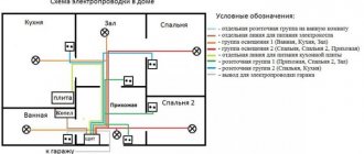
General three-phase alternating current networks are built according to a four-wire circuit, where three wires are “phase” and the fourth is “zero”. Transformer substations are built according to a scheme with a solidly grounded neutral. Long-distance transmission is carried out at high voltage, which is then reduced at substations to a voltage of 0.4 kV and distributed to consumers.
Household objects are connected using a single-phase circuit. In this case, two wires are required: “phase” and “neutral”.
Other parameters for high-quality pictures
In addition to the refresh rate, there are other necessary parameters for a high-quality image that need to be taken into account when choosing a modern LCD TV.
Optimal resolution
The first thing you need to pay attention to is the resolution of the TV. The image on the display consists of small dots - pixels. Monitor resolution is the number of horizontal and vertical pixels. Modern television panels have resolutions of HD (1366x768), Full HD (1920x1080) and Ultra HD or 4K (3840x2160). When choosing a TV resolution, you need to consider the signal source and image quality. If a television receiver is purchased to watch digital terrestrial or cable television, then the picture will not be of the best quality.
HD resolution is sufficient for such content, but since it is considered outdated and is gradually fading into the background, it is better to overpay a small amount and purchase a Full HD TV receiver. In addition, you need to choose a diagonal of no more than 42 inches, otherwise the image will be very bad.
A television receiver with a resolution of 1920x1080 is suitable for satellite television or other high-quality signal, for example, for watching movies from USB drives or via the Internet. The screen diagonal can be any. Today a new standard is gaining popularity - Ultra HD. Even though there's not a lot of relevant content out there right now, it's worth buying a TV with a display that's capable of staying up-to-date even in a few years when 4K becomes widespread. Today, on such TVs you can watch Blu-Ray movies through an appropriate player connected to the TV receiver using an HDMI cable.
Matrix type
There are several types of TVs on the market today:
- LCD TV with CCFL backlight (fluorescent lamps) - budget models;
- LCD TVs with LED backlighting (light emitting diodes) are modern devices characterized by increased contrast and better images;
- OLED (Organic Light-emitting Diode) – TVs based on organic crystals. They do not require a separate backlight; these TVs provide high quality color reproduction and incredible depth of black.
Until recently, plasma TVs were popular on the market, but today this technology is not in demand due to its high cost and many disadvantages. In addition to the type of TV, image quality also depends on which of the three types of matrices is used in their manufacture - TN, IPS and VA.
TN matrices are installed on budget television receivers; they have low color rendering and a poor viewing angle. IPS matrices have a good color gamut, good contrast and a wide viewing angle.
At the same time, they are very expensive. VA is an intermediate link between TN and IPS. They have slightly worse color rendition and viewing angle than IPS matrices, but they have much better contrast and lower cost.
Flat screen or curved
Most modern television panels are equipped with a flat screen. Expensive TV models from manufacturers such as Samsung, Haier, LG, etc. have curved displays.
Watching movies on it is exciting because... the image turns out three-dimensional and realistic, but there is a drawback - the picture is distorted when viewed from the side. Therefore, you can only buy such a TV receiver if it is installed opposite the viewing location.
Relationship between frequency and operation of electrical equipment
Current frequency is one of the parameters of electricity that affects the stable operation of electrical installations and equipment. When supplying energy to the consumer, this parameter is strictly controlled, just like voltage.
The thread of relationship is expressed by the formula for the nominal number of revolutions per minute for rotating machines. Efficiency (coefficient of performance) is inherent in the very design of the units. It is maximum at:
n = 60f/p,
Where:
- n – number of rpm;
- f – frequency;
- p – number of pairs of poles.
The number of revolutions of the generator turbine is directly related to the frequency of the generated alternating current; the resulting frequency is responsible for the optimal rotation mode of the consumer's electric motor. When the frequency in the network decreases, the machine speed is reduced automatically. The shaft is overloaded and the engine suffers.
At the same time, the production line into which it transfers rotational energy also undergoes changes in operation:
- the speed of the conveyor changes, which entails a failure of the technological process and ultimately defects;
- the power and rotation speed of pumps and fans are reduced, which leads to unstable operation of the systems in which they are installed;
- a 1% decrease in frequency in the power system leads to a drop in the total power at the load to 2%.
Frequency meters are used to monitor this important electrical parameter.
Attention! A decrease in frequency by 10-15% causes the productivity of mechanisms even at the power plant itself to drop to zero. At a current frequency in the network of 50 Hz (the critical value is 45 Hz), an avalanche decline occurs.
Capacitance
In a DC circuit, no current flows through the capacitor. For alternating current, a capacitor has a finite resistance that is inversely proportional to its capacitance. In an AC circuit, the capacitor resistance is less than in a DC circuit.
In such a circuit, voltage fluctuations lag behind current fluctuations in phase by \( \pi/2 \). Fluctuations in current and voltage occur according to the law:
Amplitude of current in the coil: \( I_m=C\omega U_m. \).
If we introduce the notation \( X_C=\frac{1}{\omega C} \), we obtain a relationship between the amplitude values of current and voltage, similar to Ohm’s law: \( I_m=\frac{U_m}{X_C} .\)
Capacitance \( X_C \) is the reciprocal of the product of the cyclic frequency and the electrical capacitance of the capacitor. Capacitance is inversely proportional to frequency.
The physical meaning of capacitance: a change in alternating current at any time is counteracted by the electric field between the plates of the capacitor.
In an alternating current circuit, fluctuations in current and EMF occur according to a sinusoidal law with the same cyclic frequency \( \omega \) and phase difference \( \varphi \):
The ratios of the amplitude values of current \( I_m \) and EMF \( \varepsilon_m \) in an alternating current circuit are related by Ohm’s law for an alternating current circuit :
It says: the amplitude of the alternating current is directly proportional to the amplitude of the emf and inversely proportional to the total resistance of the circuit:
The quantity \( Z \) is called the impedance of the alternating current circuit.
Electrical energy has the following advantages over other types of energy:
- can be transmitted over long distances with low losses;
- convenient to distribute between consumers;
- easily converted into other forms of energy.
Currently, AC energy is produced and used. This is due to the ability to convert its voltage and current with low energy losses, which is especially important when transmitting electricity over long distances.
The following types of power plants are distinguished:
- thermal;
- hydroelectric power stations;
- atomic.
Receiving alternating current
Alternating current is obtained using an alternating current generator.
An alternator (electromechanical alternator) is a device that converts mechanical energy into electrical energy. The operation of an alternating current generator is based on the phenomenon of electromagnetic induction.
The process of producing alternating current can be considered using the example of rotating a coil of wire in a uniform magnetic field. The magnetic flux through the coil area is equal to:
If the rotation period of the turn is \( T \), then the angle is \( \alpha=\frac{2\pi t}{T}=\omega t \).
Then \( \Phi=BS\cos\omega t. \)
The induced emf changes according to the law \( e=-\Phi'=BS\omega\sin\omega t=\varepsilon_m\sin\omega t. \)
EMF amplitude \( \varepsilon_m=BS\omega. \)
If the frame contains \( N \) turns, then \( \varepsilon_m=NBS\omega. \)
Main parts of alternator:
- stator winding with a large number of turns, an emf is induced in it. The stator consists of individual electrical steel plates to reduce eddy current heating;
- The rotor (the rotating part of the generator) creates a magnetic field. To obtain the desired frequency, alternating current may have several pairs of poles. At hydroelectric power plants, the number of pole pairs in the generator is 40–50, at thermal power plants – 10–16;
- voltage relief terminals.
Industrial generators produce a voltage of about 104 V. The industrial frequency of alternating current in our country is 50 Hz.
Electricity transmission
Electricity is produced mainly away from the main energy consumers, where fuel resources are available.
From the power plant, alternating current flows through the power transmission line (PTL) wires to various consumers of electrical energy. To reduce losses during AC transmission, it is necessary to use high voltage. The longer the line, the higher the voltage should be. In high-voltage power lines it can reach 500 kV. Generators at power plants produce voltage of 16–20 kV. Consumers do not need high voltage. There is a need for voltage conversion. From the power plant, the electric current is supplied to the step-up substation, then transmitted through the power line to the step-down substation, where the voltage is reduced to 6–10 kV, and then to 220–380 V. A transformer is used to convert the voltage.
A transformer is a device that converts alternating voltage without changing its frequency.
In the diagrams the transformer is designated:
Main parts of the transformer:
- closed core made of electrical steel;
- two coil windings.
The coil connected to the AC voltage source is called the primary winding; the coil to which the load is connected is the secondary winding.
The core is assembled from individual plates to reduce losses due to heating by eddy currents.
The operating principle is based on the phenomenon of electromagnetic induction. When the primary winding is connected to the poles of a voltage source, an alternating current appears in it. Voltage changes over time according to a harmonic law. The current strength in the coil and the magnetic flux created by this current will change with the same frequency.
When the magnetic flux changes in each turn of the wire of the primary winding, a variable self-induction emf occurs. This magnetic flux will also penetrate the second coil. In each of its turns, an induced emf occurs, varying according to a harmonic law with the same frequency. The number of turns in the windings is different. The ratio of the self-induction emf \( \varepsilon_1 \) in the primary winding to the induced emf in the secondary winding \( \varepsilon_2 \) is equal to the ratio of the number of turns in the primary winding \( N_1 \) to the number of turns in the secondary winding \( N_2 \):
Operating mode
- Idling mode - the secondary winding circuit is open. The voltage \( U_2 \) at its ends at any moment of time is equal to the induced emf \( \varepsilon_2 \), taken with the opposite sign. Therefore we can write:
where \( k \) is the transformation coefficient.
If \( k>1 \), then the transformer is step-down, if \( k<1 \), then it is a step-up transformer.
- Load mode. When a load is connected to the ends of the secondary winding, an alternating current appears in it. The voltage \( U_2 \) at its ends at any time differs from the induced emf \( \varepsilon_2 \) by the amount of voltage drop across the internal resistance of the secondary winding \( r \): \( U_2=\ varepsilon_2-I_2r \) or \( U_2=I_2R \).
The current power in the windings is the same. Therefore, an increase in the voltage at the input of the step-up transformer by \( k \) times is accompanied by a decrease in the current strength in the secondary coil by the same amount.
There are no friction losses in the transformer since there are no rotating parts. Core losses consist of heating and magnetization reversal losses.
The ratio of power \( P_2 \) consumed by the load to power \( P_1 \) consumed by the primary winding of the transformer is called the transformer efficiency:
Transformer efficiency is 98%.
Electrical energy consumption: industry – about 70%; Agriculture; transport; construction; means of communication; at home.
High frequency currents
HDTV – this is their abbreviation; they are used for melting metals and hardening the surface of metal products. HDTV are currents with a frequency of more than 10 kHz. Induction furnaces use HDTV by placing a conductor inside a winding through which the HDTV is passed. Under their influence, eddy currents arising in the conductor heat it up. By adjusting the strength of the HDTV, the temperature and heating rate are controlled.
Interesting. The metal to be melted can be suspended in a vacuum using a magnetic field. It does not require a crucible (a special ladle for heating). This is how very pure substances are obtained.
Advantages of using HDTV in different cases:
- rapid heating during forging and rolling of metal;
- optimal temperature conditions for soldering or welding parts;
- melt even very refractory alloys;
- cooking in microwave ovens;
- Darsonvalization in medicine.
HDTV is obtained using installations that include an oscillating circuit or electric machine generators. The stator and rotor of the generators have teeth on the sides facing each other. Their mutual movement generates a pulsation of the magnetic field. The greater the product of the number of rotor teeth and its rotation frequency, the greater the output frequency.
How many Hertz is safe for humans?
For a normally hearing person
The range of auditory perception begins at low frequencies, around 20 Hz. This roughly corresponds to the lowest pedal on an organ with labial pipes. At the other end of the range is the highest frequency that does not cause discomfort at 20,000 Hz.
Interesting materials:
How to make sound on Skype? How to make a sound-letter analysis of a word in the fall? How to remove direct pigment from hair? How to remove the restriction on registration actions? How to remove direct action pigment from hair? How to delete everything from an iPhone and make it new? How to find out the expiration date of a foreign passport? How to find out when a major home renovation will be done? How do I know when my Windows 10 license expires? How do you know when a photo was taken?
Pulsation period and frequency
The frequency of alternating current may have another name - ripple. The pulsation period is the time of a single pulsation.
Cycle intensity
For an electrical network with a frequency of 50 Hz, the pulsation period will be:
T = 1/50 = 0.02 s.
If necessary, knowing this dependence, you can calculate the frequency from the cycle time.
The danger of multi-frequency charges
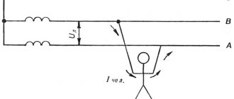
Both direct and alternating current at certain values pose a danger to humans. Up to 500 V the difference in safety is in the ratio 1:3 (42 V DC to 120 V AC).
At values above 500 V, this ratio levels out, with constant electricity causing burns and electrolysis of the skin, while changing electricity causes convulsions, fibrillation and death. Here the pulsation frequency is of great importance. The most dangerous frequency range is from 40 to 60 Hz. Further, with increasing frequency, the risk of damage decreases.
Effect of frequency on threshold current
The frequency of alternating electricity is an important parameter. It affects not only the operation of consumer electrical installations, but also the human body. By changing the frequency of electrical oscillations, it is possible to change technological processes in production and the quality of the generated energy.
Electrification of railways using alternating current[edit]
The Russian AC passenger electric locomotive EP1P is produced at the Novocherkassk Electric Locomotive Plant.
In Russia and the republics of the former USSR, about half of all railways are electrified using single-phase alternating current with a frequency of 50 Hz. Voltage ~ 25 kV (usually up to 27.5 kV, taking into account losses)
is fed to the contact wire, the second (return) wire is the rails.
Electrification is also carried out according to the 2 × 25 kV (two twenty-five kilovolts each)
, when a voltage of ~ 50 kV is applied to a separate supply wire
(usually up to 55 kV, taking into account losses)
, and half the voltage of 50 kV is applied to the contact wire from autotransformers
(i.e. 25 kV)
. Electric locomotives and AC electric trains do not require alteration when operating on 2 × 25 kV sections.
A policy is being pursued to further expand the AC traction range both through newly electrified sections and through the transfer of some lines from direct current to alternating current. Transferred to 1990s - 2000s:
- on the East Siberian Railway: section Slyudyanka - Irkutsk - Zima; - on the Oktyabrskaya Railway: section Loukhi - Murmansk; — on the Volga Railway: Saratov and Volgograd railway junctions; - on the North Caucasus Railway: sections Mineralnye Vody - Kislovodsk and Beshtau - Zheleznovodsk.
It should be noted that dual-system electric locomotives are also produced that can operate on both alternating and direct current (see VL61D, VL82 and VL82M, EP10, EP20).
What the market currently offers
The most modern panels today are considered to have a scanning frequency of 600 and 800 Hz with built-in Sub-Field Driving technology, which promises unsurpassed picture quality. There are many doubts about such characteristics. Distrust in manufacturers was born a long time ago, when such equipment was just beginning to enter the market. In those days, marketers did not hesitate to attribute hertz when image finishing technologies inserted not copies of frames, but simply black pictures that the eye was not able to perceive. Thus, quality did not improve, but sales of digital electronics went very well. Modern LCD TVs of well-known brands correspond to the parameters stated in the passport, and there is no need to doubt this. It is more important to take care of the availability of the necessary cables that allow you to transmit digitized satellite or cable TV channels.
Summarizing
Taking into account all relevant parameters, several conclusions can be drawn.
- Scanning provides a smooth image and a clear storyboard of moving objects.
- The resolution ensures realistic rendering of each frame, when you can see all the details; color, movement of water or people are accurately conveyed.
- When choosing which TV model is better, it is worth analyzing all the key characteristics together so that both the screen resolution and frame refresh rate are at the same level.
Also, feel free to include and compare the image in the store before purchasing. Consultants will never be able to describe in words the quality of the picture of a particular model. Maximum comfort and satisfaction from a new acquisition will be at its best if you approach the choice with a degree of criticality.