About virtual oscilloscopes.
I once had a fix idea: sell an analog oscilloscope and buy a digital USB oscilloscope to replace it. But, having wandered around the market, I discovered that the most budget oscilloscopes “start” at $250, and the reviews about them are not very good. More serious devices cost several times more.
So, I decided to limit myself to an analog oscilloscope, and to build some diagram for the site, use a virtual oscilloscope.
I downloaded several software oscilloscopes from the network and tried to measure something, but nothing good came of it, since either it was not possible to calibrate the device, or the interface was not suitable for screenshots.
I had already abandoned this matter, but when I was looking for a program to measure the frequency response, I came across the “AudioTester” software package. I didn’t like the analyzer from this kit, but the Osci oscilloscope (hereinafter I will call it “AudioTester”) turned out to be just right.
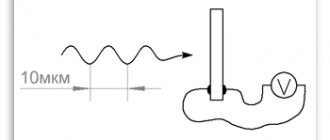
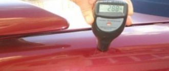
This device has an interface similar to a conventional analog oscilloscope, and the screen has a standard grid that allows you to measure amplitude and duration. https://oldoctober.com/
The disadvantages include some instability of work. The program sometimes freezes and in order to reset it you have to resort to the help of Task Manager. But all this is compensated by the familiar interface, ease of use and some very useful functions that I have not seen in any other program of this type.
Attention! The AudioTester software package includes a low frequency generator. I don't recommend using it because it tries to control the audio card driver itself, which can result in permanent audio muting. If you decide to use it, take care of a restore point or an OS backup. But, it’s better to download a normal generator from “Additional materials”.
Another interesting program for the Avangard virtual oscilloscope was written by our compatriot O.L. Zapisnykh.
This program does not have the usual measuring grid, and the screen is too large for taking screenshots, but it does have a built-in amplitude voltmeter and frequency meter, which partially compensates for the above disadvantage.
Partly because at low signal levels both the voltmeter and the frequency meter begin to lie a lot.
However, for a novice radio amateur who is not used to perceiving diagrams in Volts and milliseconds per division, this oscilloscope may be quite suitable. Another useful property of the Avangard oscilloscope is the ability to independently calibrate the two available scales of the built-in voltmeter.
So, I will talk about how to build a measuring oscilloscope based on the AudioTester and Avangard programs. Of course, in addition to these programs, you will also need any built-in or separate, most budget audio card.
Actually, all the work comes down to making a voltage divider (attenuator) that would cover a wide range of measured voltages. Another function of the proposed adapter is to protect the audio card input from damage when high voltage comes into contact with the input.
Return to top to menu.
Product customization
After assembling the USB oscilloscope, the last step is to the EEPROM flash 24LC64 memory chip For this:
- Download and install the Cypress Suite application on your computer.
- Launch the program and go to the EZ Console .
- Click on the inscription “ LG EEPROM ”.
- A window with the firmware file . Select it and run it with the Enter .
- If the error “ Error ” appears, start the firmware operation again.
- After the process has completed successfully, the message “ Done ” should appear. The oscilloscope is ready for use.
Before launching an oscilloscope based on an external audio adapter, do the following:
- Save the files miniscope.exe, miniscope.ini and miniscope.log from the downloaded archive in a separate folder. Open miniscope.exe .
- After starting the program, go to the settings and perform the actions shown in the pictures.
- To check functionality give a test signal. A sine wave should appear.
The device is ready for use.
Calibration is necessary for the device, which operates through an attenuator and an internal sound card. To do this, apply a signal with a known amplitude and frequency to the gadget. Having achieved a stable scan, turn on the measuring grid . By coordinating the actions of the trimming resistor with the adjustments on the control panel, bring the grid values to the original values.
If you cannot display the values correctly, you can adjust the grid using the audio controls on your computer. To do this, open the volume control located on the taskbar and, moving the slider, get the desired signal level.
Finished products must be grounded . Be careful when connecting a signal to the audio adapter port.
Technical data and scope.
Since there is an isolation capacitor in the input circuits of the audio card, the oscilloscope can only be used with a “closed input”. That is, only the variable component of the signal can be observed on its screen. However, with some skill, using the AudioTester oscilloscope you can also measure the level of the DC component. This can be useful, for example, when the multimeter reading time does not allow you to record the amplitude value of the voltage on a capacitor charging through a large resistor.
The lower limit of the measured voltage is limited by the noise level and background level and is approximately 1 mV. The upper limit is limited only by the parameters of the divider and can reach hundreds of volts.
The frequency range is limited by the capabilities of the audio card and for budget audio cards is: 0.1Hz... 20kHz (for a sine wave signal).
Of course, we are talking about a rather primitive device, but in the absence of a more advanced device, this one may well do.
The device can help in repairing audio equipment or be used for educational purposes, especially if it is supplemented with a virtual low-frequency generator. In addition, using a virtual oscilloscope it is easy to save a diagram to illustrate any material, or for posting on the Internet.
Return to top to menu.
Homemade set-top box with Bluetooth module
If a wider frequency range is required, then the above option will not work. This is where a new option comes to the rescue - a separate gadget, which is a set-top box with an analog-to-digital converter that provides signal transmission in digital form. In this case, the audio path of a smartphone or tablet is no longer used, which means that higher measurement accuracy can be achieved. In fact, at this stage they are only a portable display, and all information is collected by a separate device.
You can assemble an oscilloscope from an Android tablet with a wireless module yourself. There is an example on the network where a similar device back in 2010 was implemented using a two-channel analog-to-digital converter based on the PIC33FJ16GS504 microcontroller, and the LMX9838 Bluetooth module served as a signal transmitter. The device turned out to be quite functional, but difficult to assemble, so for beginners it will be an impossible task to make it. But, if desired, finding a similar project on the same amateur radio forums is not a problem.
Electrical diagram of the oscilloscope hardware.
The drawing shows the hardware part of the oscilloscope - “Adapter”.
To build a two-channel oscilloscope, you will have to duplicate this circuit. The second channel can be useful for comparing two signals or for connecting external synchronization. The latter is provided in AudioTester.
Resistors R1, R2, R3 and Rin. – voltage divider (attenuator).
The values of resistors R2 and R3 depend on the virtual oscilloscope used, or more precisely on the scales it uses. But, since the “AudioTester” has a division price that is a multiple of 1, 2 and 5, and the “Avangard” has a built-in voltmeter with only two scales interconnected by a ratio of 1:20, then using an adapter assembled according to the above the circuit should not cause inconvenience in both cases.
The input impedance of the attenuator is about 1 megohm. In a good way, this value should be constant, but the design of the divider would be seriously complicated.
Capacitors C1, C2 and C3 equalize the amplitude-frequency response of the adapter.
Zener diodes VD1 and VD2, together with resistors R1, protect the linear input of the audio card from damage in the event of accidental high voltage entering the adapter input when the switch is in the 1:1 position.
I agree that the presented scheme is not elegant. However, this circuit solution makes it possible in the simplest way to achieve a wide range of measured voltages using only a few radio components. An attenuator built according to the classical scheme would require the use of high-megaohm resistors, and its input impedance would change too significantly when switching ranges, which would limit the use of standard oscilloscope cables designed for an input impedance of 1 MOhm.
Return to top to menu.
Review of the best devices for radio amateurs
"Siglent SDS 1022"
A high-precision device that displays all signals. The upper limit of the signal frequency reaches 100 Hz. Works in 3 modes. The cost is about 16 thousand rubles. There is practically no error in operation. Processes signal frequencies from 10 to 100 Hz.
Trademark "Rigol"
Their main advantage is high performance, ease of use and adjustable sensitivity. A high-quality filter virtually eliminates errors. The device has a dual display.
The DS1102C model is widely used in work. Runs in frontal and inclined mode. The device is two-channel. The interface is simple. Price – 20 thousand rubles.
"Tektronics TDS 3064"
Despite the use of electronic lines for testing, thanks to it you can check the functioning of the board. Dual channel, wide bandwidth. Easily customizable digital filter. The advantage of the model is 20 automatic measurements. Thanks to the storage and playback function, it is possible to record data frame by frame. Built-in mathematical functions, auto-calibration, hardware frequency meter and Fourier converter. The device operates with a start delay. Compact model, nice design. Price – 22,000 rubles.
"Tektronics MSO 4104"
Like the previous model, it has a wide bandwidth of 100 MHz. At start, the sampling frequency is 1 Hz. The main feature of the model is the built-in input impedance. The device is two-channel, memory capacity is 1 MB.
High sensitivity vertically, can be triggered by video and front. Can perform all mathematical functions. The device allows you to obtain measurement data automatically. The model is quite compact and easily portable.
The price of the oscilloscope is about 18 thousand rubles.
Oscilloscopes from
Their main advantage is a user-friendly interface and versatility. Compared to previous devices, the bandwidth is not wide - about 60 MHz. Standard memory capacity (32,000 points). The device supports CP commands, screen resolution is 480 by 234 pixels. Six-digit hardware frequency counter.
USB oscilloscope review of the best models
The best in this category will be Hantek, Instrustar, SainSmart. These are the best budget options. Suitable for repairing TVs and laptops.
Based on these characteristics, choosing the right oscilloscope will be easy.
Protection from the "fool".
To protect the linear input of the audio card from accidental high voltage, zener diodes VD1 and VD2 are installed parallel to the input.
Resistor R1 limits the current of the zener diodes to 1 mA, at a voltage of 1000 Volts at the 1:1 input.
If you really intend to use an oscilloscope to measure voltages up to 1000 Volts, then as resistor R1 you can install MLT-2 (two-watt) or two MLT-1 (one-watt) resistors in series, since the resistors differ not only in power, but also according to the maximum permissible voltage.
Capacitor C1 must also have a maximum allowable voltage of 1000 Volts.
A little clarification of the above. Sometimes you want to look at a variable component of relatively small amplitude, which nevertheless has a large constant component. In such cases, you need to keep in mind that on the screen of an oscilloscope with a closed input, you can only see the alternating voltage component.
The picture shows that with a constant component of 1000 Volts and a swing of the variable component of 500 Volts, the maximum voltage applied to the input will be 1500 Volts. Although, on the oscilloscope screen we will only see a sine wave with an amplitude of 500 Volts.
Return to top to menu.
Dual Channel Devices
When it is necessary to compare two types of signals, such devices are used. There are two varieties:
- Two-channel – for observing pulses from identical Y-channels. By switching the toggle switch, output signals are alternately supplied to the CRT plates. Observe each signal of inputs Y1-Y2 separately or together. The second - at each reverse sweep.
- Double-beam - they have two separate Y-channels and a two-beam CRT design. Such a device has a joint start of the horizontal scan generator, the inclusion of vertical scan occurs for each channel separately. This allows you to see 2 waveforms simultaneously.
How to measure the output impedance of a line output?
You can skip this paragraph. It is designed for lovers of small details.
The output impedance (output impedance) of a line output designed to connect phones (headphones) is too low to have a significant impact on the accuracy of the measurements we will perform in the next paragraph.
So why measure output impedance?
Since we will use a virtual low-frequency signal generator to calibrate the oscilloscope, its output impedance will be equal to the output impedance of the Line Out of the sound card.
By making sure that the output impedance is low, we can prevent gross errors when measuring the input impedance. Although, even under the worst circumstances, this error is unlikely to exceed 3... 5%. Frankly, this is even less than the possible measurement error. But it is known that errors have a habit of “running up”.
When using a generator to repair and tune audio equipment, it is also advisable to know its internal resistance. This can be useful, for example, when measuring ESR (Equivalent Series Resistance) or simply the reactance of capacitors.
Thanks to this measurement, I was able to identify the lowest impedance output in my audio card.
If the audio card has only one output jack, then everything is clear. It is both a line output and an output for phones (headphones). Its impedance is usually small and does not need to be measured. These are the audio outputs used in laptops.
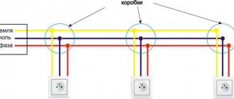
When there are as many as six sockets and there are a couple more on the front panel of the system unit, and each socket can be assigned a specific function, then the output impedance of the sockets can differ significantly.
Typically, the lowest impedance corresponds to the light green jack, which by default is the line output.
| Color/location | Switch state | |
| Phones (Ohm) | Line Out (Ohm) | |
| Lime / Rear | 5 | 230 |
| Grey/Rear | 7 | 230 |
| Lime/Front | 12 | 80 |
| Laptop | 0,7 | Doesn't switch |
An example of measuring the impedance of several different audio card outputs set to “Telephones” and “Line Out” modes.
As can be seen from the formula, the absolute values of the measured voltage do not play a role, therefore these measurements can be made long before calibrating the oscilloscope.
Calculation example.
R1 = 30 Ohm.
U1 = 6 divisions.
U2 = 7 divisions.
Rx = 30(7 – 6) / 6 = 5 (Ohm).
Return to top to menu.
Functional Features
The main function of an oscilloscope is to provide a graph of voltage over time. Typically the Y axis represents voltage and the X axis represents time. This can be useful:
- to measure parameters such as clock frequencies, duty cycles of pulse-width modulated signals, propagation delay, or rise and fall times of sensor signals;
- to warn the user about the presence of failures in the system or interceptors;
- for research (observation, recording, measurement) of amplitude and time parameters.
For information. The measurement ranges are huge. For example, on a relatively cheap oscilloscope you can adjust from 5 mV/cm to 5 V/cm (vertical scale) and from 2 µs/cm to 20 s/cm (horizontal scale).
Other device features:
- Display and calculate the frequency and amplitude of an oscillating signal;
- Show voltage and time. This function is most often used in experimental laboratories;
- Help resolve any faulty project components by reviewing the expected outcome;
- Show changes in AC or DC voltage.
Waveforms of parameters
To better understand the functions of the device, you need to become familiar with the terms used and what they represent:
Bandwidth indicates the range of frequencies that the device can accurately measure; Gain accuracy measures how accurately the vertical system attenuates or enhances the signal. The value is indicated in percentage error; Time base or horizontal precision indicates how accurately the horizontal system represents the timing of a signal. This is displayed as a percentage error; Rise time is another way of describing the usable frequency range of an instrument. The rise time must be taken into account when measuring pulses and steps. The instrument cannot accurately display pulses with a rise time faster than the oscilloscope's specified rise time; Vertical sensitivity measures how much a vertical amplifier can boost a weak signal. Vertical sensitivity is usually specified in mV/div (millivolts per division). The smallest voltage that a general purpose oscilloscope can detect is typically about 1 mV per vertical division of the screen; Sweep Speed – This setting specifies how quickly the trace can move across the screen. This is usually specified in ns/div (nanoseconds per division); The sampling rate on a digital oscilloscope indicates how many samples per second the A to D converter can take. The maximum sampling rate is usually specified in MPs (megapixels per second). The faster the oscilloscope can sample, the more accurately it can represent the subtle details of the signal
The minimum sample rate can also be important if you need to watch slowly changing signals over long periods of time. Typically, the sampling rate changes with changes made to the control to maintain a constant number of waveform points in the waveform record; The record length of a digital oscilloscope indicates the number of waveforms the device can acquire for each record.
The maximum recording length depends on its memory. It is possible to obtain a detailed image of the signal over a short period of time, or a less detailed image over a longer period of time.
How to measure the input impedance of a linear input?
To calculate the attenuator for the linear input of an audio card, you need to know the input impedance of the linear input. Unfortunately, it is impossible to measure the input resistance using a conventional multimeter. This is due to the fact that there are isolation capacitors in the input circuits of audio cards.
The input impedances of different audio cards can vary greatly. So, this measurement will still have to be done.
To measure the input impedance of an audio card using alternating current, you need to apply a sinusoidal signal with a frequency of 50 Hz to the input through a ballast (additional) resistor and calculate the resistance using the given formula.
A sinusoidal signal can be generated in a software low-frequency generator, a link to which is in the “Additional Materials”. Amplitude values can also be measured using a software oscilloscope.
The picture shows the connection diagram.
The voltages U1 and U2 must be measured with a virtual oscilloscope in the corresponding positions of the SA switch. There is no need to know the absolute voltage values, so the calculations are valid until the device is calibrated.
Calculation example.
R1 = 50kOhm.
U1 = 100
U2 = 540
Rx = 50 * 100 / (540 – 100) ≈ 11.4 (kOhm).
| Color/Location | Impedance (kOhm) |
| Red/Rear | 82 |
| Black/Rear | 75 |
| Lime/Front | 11,4 |
| Pink/Front | 50 |
| Laptop | 8,5 |
Here are the results of impedance measurements of various line inputs.
As you can see, the input resistances differ significantly, and in one case, almost an order of magnitude.
Return to top to menu.
Step-by-step instructions for assembling the DSO138 construction set
You should consider in more detail the detailed instructions for manufacturing an oscilloscope of this brand, because other models are assembled in a similar way.
It is worth noting that in this model the board comes immediately with a soldered 32-bit Cortex microcontroller on the M3 core. It operates two 12-bit inputs with a characteristic of 1 μs and operates in a maximum frequency range of up to 72 MHz. Having this device already installed makes the task somewhat easier.
Step 1. It is most convenient to start installation with SMD components. You need to take into account the rules when working with a soldering iron and a board: do not overheat, hold for no longer than 2 seconds, do not connect different parts and tracks together, use solder paste and solder.
Step 2. Solder the capacitors, inductors and resistances: you need to insert the specified part into the space provided for it on the board, cut off the excess length of the leg and solder it on the board. The main thing is not to confuse the polarity of the capacitors and not to close adjacent tracks with a soldering iron or solder.
Step 3. Install the remaining parts: switches and connectors, buttons, LED, quartz
Particular attention should be paid to the diode and transistor side. Quartz has metal in its structure, so you need to ensure that there is no direct contact of its surface with the traces of the board or take care of the dielectric lining
Step 4. 3 connectors are soldered to the display board. After completing manipulations with the soldering iron, you need to rinse the board with alcohol without auxiliary products - no cotton wool, discs or napkins.
Step 5. Dry the board and check how well the soldering was done. Before connecting the screen, you need to solder two jumpers to the board. The existing bitten-off pins of the parts will be useful for this.
Step 6. To check operation, you need to connect the device to a network with a current of 200 mA and a voltage of 9 V.
The check consists of taking indicators from:
- 9 V connector;
- Test point 3.3 V.
If all parameters correspond to the required values, you need to disconnect the device from the power supply and install the JP4 jumper.
Step 7. You need to insert a display into the 3 available connectors. You need to connect an oscilloscope probe to the input and turn on the power yourself.
The result of correct installation and assembly will be the appearance on the display of its number, firmware type, version and developer’s website. After a few seconds, you will be able to see sine waves and a scale when the probe is turned off.
How to calculate a voltage divider (attenuator)?
The maximum unlimited amplitude of the audio card input voltage, at the maximum recording level, is about 250 mV. A voltage divider, or as it is also called an attenuator, allows you to expand the range of measured voltages of an oscilloscope.
The attenuator can be constructed using different circuits, depending on the division coefficient and the required input resistance.
Here is one of the divider options that allows you to make the input resistance a multiple of ten. Thanks to the additional resistor Rext. you can adjust the resistance of the lower arm of the divider to some round value, for example, 100 kOhm. The disadvantage of this circuit is that the sensitivity of the oscilloscope will depend too much on the input impedance of the audio card.
So, if the input impedance is 10 kOhm, then the division ratio of the divider will increase tenfold. It is not advisable to reduce the resistor of the upper arm of the divider, since it determines the input resistance of the device, and is the main element in protecting the device from high voltage.
So, I suggest you calculate the divider yourself based on the input impedance of your audio card.
There is no error in the picture; the divider begins to divide the input voltage already when the scale is 1:1. Calculations, of course, need to be done based on the actual ratio of the divider arms.
In my opinion, this is the simplest and at the same time the most universal divider circuit.
Using the presented formulas, you can calculate the attenuator for the adapter if you agree with the proposed circuit.
An example of divisor calculation.
Initial values.
R1 – 1007 kOhm (result of measuring a 1 mOhm resistor).
Rin. – 50 kOhm (I chose the higher-impedance input of the two available on the front panel of the system unit).
Calculation of the divider in the switch position 1:20.
First, using formula (1), we calculate the division coefficient of the divider, determined by resistors R1 and Rin.
(1007 + 50)/ 50 = 21,14 (once)
This means that the total division ratio in the switch position 1:20 should be:
21,14*20 = 422,8 (once)
We calculate the resistor value for the divider.
1007*50 /(50*422,8 –50 –1007) ≈ 2,507 (kOhm)
Calculation of the divider in the switch position 1:100.
We determine the overall division ratio at the switch position of 1:100.
21,14*100 = 2114 (once)
We calculate the resistor value for the divider.
1007*50 / (50*2114 –50 –1007) ≈ 0,481 (kOhm)
To make calculations easier, take a look at this link: How to pair Notepad with the Windows Calculator to make calculations easier?
If you are going to use only the Avangard oscilloscope and only in the 1:1 and 1:20 ranges, then the accuracy of resistor selection may be low, since the Avangard can be calibrated independently in each of the two available ranges. In all other cases, you will have to select resistors with maximum accuracy. How to do this is written in the next paragraph.
If you doubt the accuracy of your tester, then you can adjust any resistor with maximum accuracy by comparing ohmmeter readings.
To do this, instead of a permanent resistor R2, a tuning resistor R* is temporarily installed. The resistance of the trimming resistor is selected so as to obtain the minimum error in the corresponding division range.
Then the resistance of the trimming resistor is measured, and the constant resistor is already adjusted to the resistance measured by an ohmmeter. Since both resistors are measured with the same device, the ohmmeter error does not affect the measurement accuracy.
And these are a couple of formulas for calculating the classic divisor. A classic divider can be useful when a high input impedance of the device (mOhm/V) is required, but you don’t want to use an additional dividing head.
Return to top to menu.
Let's put it all together
It seems that everything is simple, all that remains is to collect everything into a single pile.
To save you time, I posted this project on github github.com/dlinyj/realtime_graph_on_js Since I want to give you a working example, and the program is a trade secret, I made a simple Python script that generates random data for display.
#!/usr/bin/env python3 import random f = open(“/var/www/html/result.dat”, “w”) for i in range (20): f.write(“%d\t% d\t%d\t%d\t\n" % (random.randint(0, 255), random.randint(0, 255), random.randint(0, 255), random.randint(0, 255 ))) f.close() The basis of everything is the CGI in bash, which I wrote about above, which calls this Python script. #!/bin/bash echo "Content-type: text/html;charset=utf-8" echo /usr/bin/python3 /usr/lib/cgi-bin/test.py > /dev/NULL 2&>1 echo “true” exit 0 The source code of the entire web page can be viewed here.
First, I configure the parameters of the graph itself. This is all taken from ready-made examples of the Chart.js framework.
The schedule is updated using a timer. Every 2000 ms, the gen_graph() function is called, which calls the CGI script described above.
var gen_graphUrl = "cgi-bin/gen_graph.sh"; function gen_graph() { $.ajax({ url: gen_graphUrl, success: function(result) { parseData(); } }); } parseData(); var timerId = setInterval(function() { gen_graph(); }, 2000); function stop_reload () { clearInterval(timerId); }; The parseData() function parses CSV data and converts it from json format: function parseData() { Papa.parse(“result.dat”, { download: true, complete: function(results) { createGraph(results.data); } }); } As a result, our test case works like this:
How to select or adjust voltage divider resistors?
Since radio amateurs often have difficulty finding precision resistors, I will talk about how you can adjust common resistors for a wide range of applications with high accuracy.
High-precision resistors are only several times more expensive than conventional ones, but on our radio market they are sold for 100 pieces, which makes their purchase not very advisable.
Using trim resistors.
As you can see, each arm of the divider consists of two resistors - a constant one and a trimmer one.
Disadvantage: cumbersome. Accuracy is limited only by the available accuracy of the measuring instrument.
Selection of resistors.
Another way is to select pairs of resistors. Accuracy is ensured by selecting pairs of resistors from two sets of resistors with a large spread. First, all resistors are measured, and then pairs are selected whose sum of resistances most closely matches the circuit.
It was in this way, on an industrial scale, that the divider resistors for the legendary TL-4 tester were adjusted.
The disadvantage of this method is that it is labor intensive and requires a large number of resistors.
The longer the list of resistors, the higher the selection accuracy.
Adjusting resistors using sandpaper.
Even industry does not shy away from adjusting resistors by removing part of the resistive film.
However, when adjusting high-resistance resistors, it is not allowed to cut through the resistive film. For high-resistance film resistors MLT, the film is applied to a cylindrical surface in the form of a spiral. Such resistors must be filed extremely carefully so as not to break the circuit.
Precise adjustment of resistors in amateur conditions can be done using the finest sandpaper - “null sandpaper”.
First, the protective layer of paint is carefully removed from the MLT resistor, which obviously has a lower resistance, using a scalpel.
The resistor is then soldered to the “ends”, which are connected to the multimeter. By careful movements of the “zero” skin, the resistance of the resistor is brought to normal. When the resistor is adjusted, the cut area is covered with a layer of protective varnish or glue.
What a “zero” skin is is written here.
In my opinion, this is the fastest and easiest way, which, nevertheless, gives very good results.
Return to top to menu.
Introduction
It is impossible to find an industry today that does not use electronic instruments and electronic devices of measuring technology, automation and computer technology.
Continuous change and improvement of the element base, a wide range of produced reprogrammable and ready-to-use electronic modules and assemblies allow us to develop and introduce into production electronic devices for a wide variety of purposes in a fairly short time. This is facilitated by a variety of hardware and software support tools for developers. The design and creation of an electronic device is a complex process involving several stages of iterative functional design. As a rule, first this is the initial development of a circuit diagram and calculation of the nominal values of the elements, then the design and manufacture of a printed circuit board, conducting bench tests and finalizing the functional and circuit diagram of the device based on their results, making changes to the printed circuit board, repeating bench tests and making adjustments, until all requirements of the technical specification are satisfied. The use of modern computer technologies greatly simplifies the task. For these purposes, various packages of application programs for the end-to-end design of electronic equipment are designed, which are a type of CAD - computer-aided design systems. All modern computer packages for end-to-end design of electronic equipment require entering the design in the circuit diagram editor, after which a list of connections necessary for the operation of the electronic modeling program is generated. As a counting core, almost all programs of this kind use the SPICE (Simulation Program with Integrated Circuit Emphasis) software module developed at the University of California, Berkeley, or a variation thereof. Due to the use of a single computational algorithm, electronic device simulation programs from different manufacturers represent only different graphical shells that provide the user with access to the functions of the SPICE software module, as well as some additional capabilities for processing and presenting the obtained data.
An interesting product of this kind is the Circuit Design Suite Multisim offered by National Instruments Corporation. This is a convenient and intuitive platform designed for the full cycle of designing electronic devices. It links the design and testing processes, providing the electronics designer with the flexible capabilities of virtual instrument computer technology. Multisim provides a large number of professional design features, focused on the latest modeling tools and an improved component base.
Among a number of other similar programs, Multisim has the most simple and easy-to-learn interface. The peculiarity of this program is the presence of a set of control and measuring instruments, in appearance, controls and characteristics as close as possible to their industrial analogues. This helps, simultaneously with mastering the circuit modeling program, to acquire practical skills in working with such common instruments in the measuring laboratory as a multimeter, generator, and oscilloscope.
The operating principle of all Multisim tools (connection to the circuit, use) is identical to the operating principle of real analogues of these devices.
Construction and details.
The elements of the adapter circuit are housed in a rectangular duralumin housing.
The attenuator division ratio is switched using a toggle switch with the middle position.
The standard CP-50 connector is used as the input jack, which allows the use of standard cables and probes. Instead, you can use a regular 3.5mm Jack audio jack.
Output connector: standard 3.5mm audio jack. The adapter connects to the linear input of the audio card using a cable with two 3.5mm jacks at the ends.
The assembly was carried out using the hinged mounting method.
To use the oscilloscope you will need another cable with a probe at the end.
How to make it is written in detail here.
Return to top to menu.
Step 11: Analyze the signal from the remote control
You can see the IR signal from the remote control using TIL78 phototransistor.
Assemble the circuit according to the drawing and follow the following instructions:
- Set the "dt" value to 2 ms or 100 µs.
- Turn on Ch-0's "Trigger".
- Increase the level by dragging the slider (see picture).
- Press the "UMA" button: the oscilloscope will enter standby mode.
- Press any button on the remote control, after pointing it at the phototransistor.
- Analyze the graph.
How to calibrate a virtual oscilloscope?
To calibrate an oscilloscope, you need to have at least some kind of measuring instrument. Any pointer tester or digital multimeter that you trust will do.
Due to the fact that some testers have too high an error when measuring alternating voltage up to 1 Volt, we perform calibration at the maximum possible voltage, but unlimited in amplitude.
Before calibration, we make the following settings.
Disable the audio card equalizer.
“Line output level”, “WAVE level”, “Line input level” and “Recording level” are set to the maximum gain position. This will ensure repeatability of the result during further measurements.
Having reset the generator settings just in case using Command > Get Generator Default Setting, set the “Gain” (level) to 0db.
We select the generator frequency of 50Hz using the “Frequency Presets” switch, since all amateur instruments for measuring alternating voltage can operate at this frequency, and our adapter cannot yet operate correctly at higher frequencies.
Switch the adapter input to 1:1 mode.
Looking at the oscilloscope screen, use the Trim generator knob to select the maximum unlimited signal level.
The signal may be limited both at the input of the audio card and at its output, and the accuracy of calibration may be significantly reduced. AudioTester even has a special overload indicator, which is highlighted in red in the screenshot.
Using a tester, we measure the voltage at the generator output and calculate the corresponding amplitude value.
Example.
Voltmeter reading = 1.43 Volts (rms).
We get the amplitude value.
1,432*√2 = 2,025 (Volt)
The “Options > Calibrate” command brings up the “AudioTester” calibration window.
And although the dimension in “mVrms” is indicated next to the input window, which in theory should mean the root mean square value, in reality, in the “oszi v2.0c” oscilloscope from the “AudioTester” kit, the entered values correspond to... it’s not clear what. Which, however, does not at all prevent you from accurately calibrating the device.
By entering values in small increments, you can precisely adjust the size of the sine wave image to the amplitude value calculated above.
The picture shows that the signal amplitude is a little more than two divisions, which corresponds to 2.02 Volts.
The accuracy of the display of the amplitude of the signals received from the 1:20 and 1:100 inputs will depend on the accuracy of the selection of the corresponding divider resistors.
When calibrating the Avangard oscilloscope, the values obtained during measurement by the tester must also be multiplied by √2, since both the voltmeter and the Avangard calibrator are designed for amplitude values.
Enter the resulting value into the calibration window in millivolts - 2025 and press Enter.
To calibrate the second range of the Avangard oscilloscope, which is about, you must first calculate the real division factor by comparing the readings of the built-in voltmeter in two divider ranges: 1:1 and 1:20. The oscilloscope voltmeter should be in the “12.5” position
Example.
122 / 2323 = 19,3
Then you need to correct the “calibr” file, which can be opened in Notepad. On the left is the file before editing, and on the right is after.
The "calibr" file is located in the same directory as the current copy of the program.
In the eighth line we enter the real division coefficient corresponding to the divider of the first (left) channel.
If you have built a two-channel adapter, then in the ninth line we make an amendment for the second (right) channel.
Return to top to menu.
general description
Sooner or later, probably every radio amateur will need an oscilloscope.
Based on some considerations, mostly budgetary ones, it was decided to build a computer-based device.
In this case, the computer is used to display information in a familiar graphic form. The controller's built-in ADC is used for measurement. The measured data is sent to the PC via USART.
Of course, our oscilloscope must have two channels. In addition, it must be able to measure signals with voltage on the order of the mains voltage.
In this regard, for obvious reasons, it is necessary to provide galvanic isolation of both channels between themselves and the computer.
There is some limitation on the frequency characteristics of the device being developed. This is due to the low speed of the ADC built into the controller. However, taking into account the fact that our model is budget, and the absence of high-frequency tasks in the foreseeable list of areas of application of the oscilloscope, this circumstance is not so critical.
So, the main characteristics of an oscilloscope attachment for a PC:
- two galvanically isolated measurement channels,
- maximum amplitude voltage limit in each channel up to 800 volts,
- eight-stage divider at the input of each channel,
- maximum sampling frequency 25 kHz,
- three stages of sampling frequency control - 25, 10 and 5 kHz,
- communication with a computer via the com interface - a port with galvanic isolation from the measured channels.
How to equalize the amplitude-frequency response of the adapter?
The linear input of the audio card, and the adapter circuits themselves, have some input capacitance. The reactance of this capacitance changes the division ratio of the divider at high frequencies.
To equalize the frequency response of the adapter in the 1:1 range, you need to select the capacitance of capacitor C1 so that the amplitude of the signal at a frequency of 50 Hz is equal to the amplitude of the signal with a frequency of 18-20 kHz.
Resistors R2 and R3 reduce the influence of the input capacitance and create an increase in the frequency response in the high frequency region. This rise can be compensated by selecting capacitors C2 and C3 in the corresponding ranges of 1:20 and 1:100.
I selected the following capacitances: C1 – 39pF, C2 – 10nF, C3 – 0.1nF.
Now that the Y channel of the oscilloscope's vertical deviation is calibrated and linearized, you can see what certain periodic signals, and more, look like. “AudioTester-e” has “waiting scan synchronization”.
Return to top to menu.
The best oscilloscope software for Windows PC
The following sections provide brief overviews of popular specialized programs. When choosing, you should pay attention to ease of learning, interface language, and other details, taking into account the needs of a particular user.
FrequencyAnalyzer
The program was created for processing audio signals. It is permissible to change the measurement frequency. User-selectable 8 (16) digit conversion helps establish the required accuracy. The disadvantage is the lack of a Russified version.
Winscope
This online oscilloscope does more than just show the signal. When you select the appropriate mode, Lissajous figures are displayed on the screen. The user can examine the spectral distribution in the range from 20Hz to 20kHz.
Sound oscilloscope
The 2ray Oscilloscope is well suited for studying two signals. If necessary, waveforms can be saved as graphic files. The clear interface simplifies the use of the program.
Oscilloscope Spectrum in real time
Multi-Instrument contains not only an oscilloscope, but also a generator. This software suite is complemented by a spectrum analyzer. Such equipment is suitable for complex testing of radio equipment.