I think that no person in his right mind would argue with the fact that brakes play a key role on any vehicle. In principle, you simply cannot do without them! However, few of these thinkers thought about the fact that you can also get an energy boost from braking. When the working parts of the brake mechanism come into contact (friction), a lot of heat is released and flies out into the chimney. But this energy can be directed in a more rational direction: accumulate it for reuse.
Fortunately, this is real, and this process is called recovery (partial return of energy). The system is not new and has been installed on electric and hybrid cars for quite some time, but many owners of such equipment have little understanding of the technical details of their purchase. In this topic, I want to discuss the recovery process in detail in order to prove that it is an ingenious development of designers that brings undoubted benefits to car owners.
Usage
They are trying to use the recovery principle in Formula 1 cars: a rare case when the technology was tested on production cars and then offered to the queen of motorsport. True, the designs of the so-called KERS (Kinetic Energy Recovery System) are more sophisticated here. Most teams use electric recuperation. Williams has an ultra-compact flywheel built into the box, which spins up when braking, accumulating mechanical energy and then releasing it back to the wheels:
Brake and reserve: recuperation systems in modern cars
Dozens of machines with the Bosch and Eaton system have been in operation in the United States for more than ten years, and their hybrid drive has proven to be reliable and inexpensive. The essence of the operation of such an installation lies in the capabilities of the hydraulic motor, which, when braking, pumps working fluid into a large hydraulic accumulator - a pipe with compressed gas. When the car accelerates, gas displaces liquid, the liquid rotates the same hydraulic motor and helps save fuel. The system does not have expensive batteries, and its resource is very long. The power of hydraulic motors is also high, and the cost, on the contrary, is extremely low.
One catch: the hydraulic accumulator has large dimensions and weight, and in reality its energy is enough for one or two acceleration and braking cycles; the range without turning on the internal combustion engine is only a couple of kilometers for a passenger car and hundreds of meters for a truck. When used on buses or garbage trucks, such a system allows you to completely abandon the use of traditional braking mechanisms; the hydraulic motor can slow the vehicle down to a complete stop. In this, the pneumohydraulic recuperator is even superior to electric systems, which are no longer effective at low wheel speeds.
An additional advantage is the ability to store energy for a long time, for hours and days. Unlike flywheels, which already after tens of minutes lose a significant part of the stored power. Unfortunately, Peugeot's large-scale plans were not received well by new shareholders from the Chinese Dongfeng, as well as by partners in the development of the system from Ford. But judging by the news, Chinese Dongfeng trucks may be the next mass carriers of this technology.
Electric braking with recuperation
The main competitor of these certainly interesting, but with many limitations, circuits is the classic electrical circuit with an electric motor, batteries or supercapacitors.
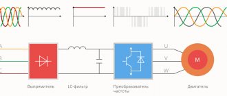
Conventional electric braking and recuperation are good because they have been used on the railway for about 60 years and have been worked out to the smallest detail. All design schemes with synchronous, asynchronous and commutator motors have long been known and calculated. The energy is transferred back to the mains, stored in batteries or supercapacitors and can be used over a long period of time.
The main problem with electric brakes is that they do not combine well with an internal combustion engine, and in order to effectively use electricity, it was necessary to combine a conventional internal combustion engine and all the attributes of an electric vehicle - batteries and a traction motor - in one mechanism. The resulting hybrids are usually called simply “hybrids” . And despite the complexity and high mass of such a scheme, at the moment it is the only one commercially used in the passenger car industry and is already very popular.
Hybrids currently turn out to be the most promising direction for automobile development in terms of reducing fuel consumption, and progress in the creation of rechargeable batteries and the development of so-called “rechargeable hybrids,” which are essentially an intermediate link between pure electric vehicles and hybrids, make them an important element in the evolution of personal mobility. motor transport.
In 1997, the first production Toyota Prius was released, which remains currently the most popular hybrid car and a trendsetter in its class . In its design, they decided to use low-power electric motors and an inexpensive nickel-metal hydride battery, also of low power, and to compensate for these shortcomings, they endowed the car with a very complex transmission with many operating modes of the internal combustion engine, electric motor and generator. The success of this scheme greatly influenced the development of similar technologies from other manufacturers. Now the number of car models with a hybrid drive has exceeded two dozen.
Ultra-compact flywheel
Having tested KERS on formulas, Ferrari tried the recovery system on a road car.
Based on the 599 GTB Fiorano coupe, the first ever Ferrari hybrid, the 599 GTB HY-KERS, appeared. The six-liter gasoline engine is assisted during acceleration by a 74-kilowatt electric motor, which generates energy during braking and allows driving on electric power for up to 5 km.
Regenerative braking
Electric traction motors used to drive urban and railway electric vehicles operate using regenerative braking (BR). At the moment when the electric motor brakes, it turns into a generator.
Power generation
Similar electric motors are used:
- in trolleybuses;
- on trams;
- in electric trains.
The electrical energy generated during the braking process is transferred back to the general power grid.
Attention! In a similar situation, electric or hybrid vehicles use this energy to charge their own battery.
Electric train with RT engines
ES electric battery - energy storage device for Formula One car 2014
Any source can be used as an energy storage device if its mass is within 20-25 kg.
So, some teams use lithium-ion or lithium polymer cells, others plan to put super-capacitors on their cars, all batteries have their advantages and disadvantages. The energy storage source combines both recovery systems MGU-H and MGU-K into a single whole, and by distributing energy flows, the entire complex of devices operates in a coordinated manner to achieve the highest possible efficiency, obtaining high power with sufficient efficiency to be able to finish the race per 100 kg of fuel.
The feasibility of a recuperator in ventilation
We can talk about the feasibility of installing recuperative ventilation by assessing the effectiveness of the system and comparing its advantages with disadvantages.
Part of the heat is taken from the exhaust air drawn outside and transferred to forced fresh jets directed inside the room. This allows you to reduce heat loss by up to 70% (+)
The need to use heat recovery is most relevant in buildings with forced air exhaust. As a rule, these are low-inertia buildings erected using innovative thermal insulation technologies (houses made of sandwich panels, gas silicate slabs, foam blocks).
In such buildings, the walls do not accumulate heat well, and natural air exchange is ineffective.
However, problems with air circulation are also typical for “traditional” buildings made of brick and concrete. The presence of sealed heat-sound-insulating PVC windows blocks circulation with a natural impulse - the flow of fresh air stops, and the draft in the ventilation duct overturns or tends to zero.
The solution to the problem of “Euro-windows” is the organization of forced ventilation. The system restores air exchange, but heat loss increases up to 60%. And here it is no longer possible to do without heat recovery.
The efficiency of the exchange process is expressed as a percentage and shows the amount of heat expended from the exhaust air to heat the fresh “intake”
Ventilation heat recovery efficiency indicator:
- 0% - open window - warm air is removed into the atmosphere, and cold air enters, lowering the temperature in the room;
- 100% - the supply air is heated to the “exhaust” temperature - technically impossible to implement;
- 30-90% - an acceptable parameter, recovery with an efficiency of 60% or more is considered good, an efficiency of over 80% is excellent heat transfer.
The efficiency of the system depends on the type of recuperator, room dimensions and air flow. In any case, the use of recovery ventilation, even with an efficiency of 30%, is more profitable than its absence. In addition to significant savings on energy resources, heat “regeneration” improves the overall microclimate in the room.
Disadvantages of using a heat exchanger:
- Energy dependence. The purchase of climate control equipment is justified if the electricity consumption is significantly less than its savings after installing the recuperator.
- Condensation. Due to temperature differences, moisture may condense on the walls of the heat exchanger. In winter, there is a possibility of icing, which can lead to a rapid decrease in efficiency or failure of the recuperator.
- Noisy work. Some models emit a hum during operation. If during the day this disadvantage is not particularly noticeable, then at night the noise causes discomfort. Recuperators with improved insulation operate quietly.
High initial investment is often the main argument against energy efficient ventilation.
It is advisable to invest money in a system that will pay off within 5-8 years. It should be taken into account that additional costs will have to be incurred to maintain the complex, for example, periodic replacement of fans
Efficiency
No machine can achieve 100% efficiency (without violating the laws of physics) since any transfer of energy will inevitably entail loss in the form of heat, light, noise, etc. The efficiency of the process depends on many factors such as the engine , battery and controller, but often the value is estimated at around 60-70%. According to Tesla, their technology typically loses 10-20% of kinetic potential when trying to capture it, and then another 10-20% when converting the stored reserves back into acceleration. These are pretty standard numbers for the bulk of electric vehicles, including cars, trucks, bikes, scooters, etc.
Note that this 70% does not tell us that regenerative braking will give a 70% increase in distance per charge. The technology will not increase the range from 100 km to 170 km. This simply means that 70% of the kinetic energy lost during braking can be regained.
Therefore, considering only the efficiency of a system means little. What should interest us more is the effectiveness of regenerative braking.
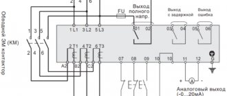
Parameters of the operating mode of the AC traction network during energy recovery
The inverter, which converts the recuperation electricity from the direct current of the traction motors into the alternating current of the electric power station, is located on the EPS and belongs to the category driven by the network.
When regenerating electricity at an alternating current of 25 kV, the active recuperation energy is generated by the EPS in the electric power plant, and the reactive energy is consumed from the external power supply network in the same way as in traction mode. This increases the reactive power consumption of electric locomotives in the intersubstation area.
————->P ¦ Mode
————->Q ¦ thrust
—————————————————
————->Q ¦ recovery
Rice. Directions of electricity in traction and recovery modes of EPS.
The angular shifts between the current and voltage of the EPS in the traction mode are for diode EPS φE = 370 el, for thyristor EPS φE = 420 el. The reactive power factor for the traction mode tg φE = Q/P for diode EPS is tg 370 = 0.754, for thyristor EPS - tg 420 = 0.9. Consequently, the reactive power consumption of the EPS in traction mode is QT = (0.75÷ 0.9)P. Reactive power consumption in traction mode is (75÷ 90)% of the active one.
The angular shifts between the current and voltage of the EPS in the recovery mode are φE = 60 el. gr. The reactive power factor for the recuperation mode tg φЭ = Q/P is tg 600 = 1.73. Consequently, the reactive power consumption of EPS in recovery mode is QР = 1.73P. Reactive power consumption in recuperation mode is 170% of the active one.
When working together in the inter-substation zone of the EPS in traction and recuperation modes, reactive power consumption increases significantly. The optimal mode in the intersubstation zone corresponds to the equality of active power consumption of EPS in traction modes Рт and active generation in recovery modes Рр (Рт = Рр). In this case, the reactive power for traction is Qt = 0.9P, the reactive power for recovery is Qp = 1.73Pt and the total reactive power consumption is Q∑ = (0.9 + 1.73)Pt = 2.63Pt. Ratio K = 2.63/0.9 = 2.92. Consequently, reactive power consumption in the intersubstation zone in the optimal recovery mode increases by 3 times. Since the ratio of active power consumption of EPS in traction and generation modes changes, it should be assumed that reactive power consumption increases in the range of 1.7 ÷ 3 times compared to traction mode.
Let's consider linear and vector diagrams of the current and voltage of the traction network in traction and recuperation modes with one-way power supply to the contact network.
Traction mode.
Rice. Linear diagram of the current and voltage of the EPS in traction mode: E1, U1 – curve of the EMF and voltage of the EPS transformer; i1t – current curve, i1(1) – first harmonic current curve.
Voltage loss in traction mode
∆ Uts = It RTS cos φT + It Xts sin φT = Iat RTS + IрХTS.
Source voltage
U1 = Ueps + ∆ Uts.
Recovery mode.
Rice. Linear diagram of the current and voltage of the EPS in recuperation mode: E1, U1 – curve of the EMF and voltage of the EPS transformer; i1Р – current curve, i1(1) – first harmonic current curve.
| Rice. Vector diagram of current and voltage in recuperation mode: Ie – total current value; Ira, Ipp – active and reactive components of the EPS current; φр – angular shift between current and voltage. |
Turbocharging is also a motor-generator
It develops a boost pressure of 3-4 bar, and the turbine is designed in such a way that a large excess of torque is created on the impeller shaft.
In conventional turbo engines, excess energy is not used in any way and simply flies out into the exhaust pipe. Here, a motor-generator is installed on the shaft, which is part of the MGU-H hybrid system. In generator mode, it generates electricity stored in the battery, thereby greatly increasing the efficiency of the engine, which greatly affects efficiency. Since the F1 has a very large turbocharger, it would likely have very significant turbo lag. Therefore, in transient modes, when the power of the exhaust flow cannot ensure the spin-up of the turbocharger shaft, until the speed of the optimal boost pressure is achieved, an electric motor is connected to help spin up the turbine. A feature and difference of some F1 2014 turbochargers is the presence of two inlet pipes on the turbine scroll. This solution makes it possible to effectively use one turbocharger in a V-shaped engine with two exhaust manifolds. Any means of regulating the turbine, westgate, etc. prohibited by FIA regulations.
Fully electric KERS system
The motor generator, mounted on the front shaft of the engine, switches to generator mode when the F1 car brakes and stores electricity in a lithium-ion battery. If it is necessary to increase power, the pilot presses the BOOST button on the steering wheel and electricity is supplied to the motor generator, which is switched to electric motor mode with a power of 80 hp, which is added accordingly to the main one (ICE). The batteries got very hot and required additional cooling. In this regard, instead of a rechargeable battery, some teams used super-capacitors without this drawback.
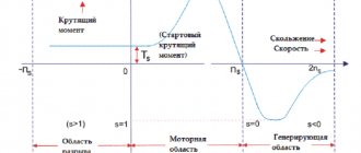
Braking of asynchronous motors
What is recuperation in relation to asynchronous machines? In this case, this is only one type of braking. The other two are:
- dynamic deceleration;
- counter braking.
Each of them has its own characteristics.
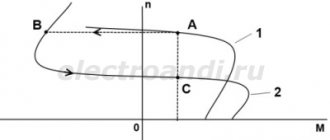
Regenerative braking of an asynchronous motor
An induction motor (IM) turns into a generator when the rotor slip in the stator field increases. This can be done in three ways:
- reducing the frequency of the supply voltage, at which the rotor begins to rotate at a speed faster than synchronous;
- in machines with two or more rotation speeds, when switching windings or changing the number of switched poles;
- in motors with a wound rotor, by changing the resistance included in the circuit of the rotor windings.
The amount of slip in all cases exceeds unity, and the machine goes into generation mode and returns energy.
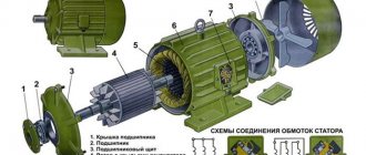
Scheme for starting a wound-rotor motor
Opposition
This method is rarely used due to the disadvantages associated with the need to swap phases with each other. This causes a change in direction of movement, but the operating current increases tenfold. In addition, it is necessary to stop further supply of voltage so that after braking the engine does not rotate in the opposite direction.
Dynamic braking of an asynchronous motor
This reduction in rotation speed is obtained by applying a constant voltage to the stator winding. The resulting magnetic field from the stator acts on the rotor windings. EMF appears in them, and current begins to flow. The strength of the braking torque that occurs when the power released is directly dependent on the rotation speed of the electric motor. The engine turns into a generator with short-circuited output terminals and supplies energy to the network.
Diagram of dynamic braking of blood pressure
Replacing or supplementing a mechanical brake with regenerative deceleration allows energy to be recovered for reuse. Recovery, as one of the ways to save raw materials and energy, allows you to increase the economy and efficiency of technological processes.