The overall power of the transformer can be approximately determined by the cross-section of the magnetic circuit. True, the error can be up to 50%, and this is due to a number of factors. The overall power directly depends on the design features of the magnetic core, the quality and thickness of the steel used, the size of the window, the amount of induction, the cross-section of the winding wire and even the quality of the insulation between the individual plates.
The cheaper the transformer, the lower its relative overall power. Of course, it is possible through experiments and calculations to determine the maximum power of a transformer with high accuracy, but there is not much point in this, since during the manufacture of the transformer, all this is already taken into account and reflected in the number of turns of the primary winding.
So, when determining the power, you can be guided by the cross-sectional area of the set of plates passing through the frame or frames, if there are two of them.
P = B * S² / 1.69
P – power in Watts, B – induction in Tesla, S – cross section in cm², 1.69 – constant coefficient.
calculation of transformer power by dimensions
Example:
First, we determine the cross-section, for which we multiply the dimensions A and B.
S = 2.5 * 2.5 = 6.25 cm²
Then we substitute the cross-sectional size into the formula and get the power. I chose 1.5Tc induction, since I have an armored twisted magnetic circuit.
P = 1.5 * 6.25² / 1.69 = 35 Watt
If you need to determine the required cross-sectional area of the manipulator based on the known power, you can use the following formula:
S = ²√ (P * 1.69 / B)
Example:
It is necessary to calculate the cross-section of an armored stamped magnetic circuit for the manufacture of a 50-watt transformer.
S = ²√ (50 * 1.69 / 1.3) = 8cm²
The magnitude of induction can be found in the table. You should not use maximum induction values, as they can vary greatly for magnetic cores of different quality.
How to determine the number of turns of the secondary winding?
To calculate the number of turns of the secondary winding, you need to know how many turns there are per volt. If the number of turns of the primary winding is unknown, then this value can be obtained using one of the methods suggested below.
First way.
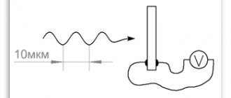
Before removing the secondary windings from the transformer frame, you need to measure the mains voltage and the voltage on one of the longest secondary windings at idle (without load). When unwinding the secondary windings, you need to count the number of turns of the winding on which the measurement was made.
Having this data, you can easily calculate how many turns of wire are per volt of voltage.
Second way.
This method can be used when the secondary winding has already been removed and the number of turns has not been counted. Then you can wind 50-100 turns of any wire as a secondary winding and make the necessary measurements. The same can be done if a transformer is used that has only a few turns in the secondary winding, such as a spot welding transformer. Then the temporary measuring winding will significantly increase the accuracy of calculations.
Once the data is received, you can use a simple formula:
ω1 / U1 = ω 2 / U2
ω 1 – number of turns in the primary winding,
ω 2 – number of turns in the secondary winding,
U1 – voltage on the primary winding,
U2 – voltage on the secondary winding.
Example:
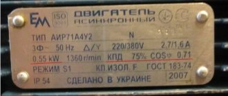
I got hold of this transformer without a secondary winding or identification marks.
I wound it as a temporary secondary winding - 100 turns.
I wound this winding with a thin wire, which I don’t mind and which I have most of. I wound it “in bulk”, which means haphazardly.
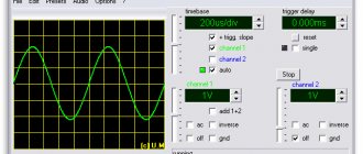
Test results.
The network voltage during measurement is 216 Volts.
The voltage on the secondary winding is 20.19 Volts.
Determine the number of turns per volt at 216V:
100 / 20.19 = 4.953 vit./Volt
Here you should not skimp on accuracy, since the error accumulates during measurements. Fortunately, we don’t count on paper.
We calculate the number of turns of the primary winding:
4.953 * 216 = 1070 vit.
Now you can determine the number of turns per volt at 220V.
1070 / 220 = 4.864 vit./Volt
We calculate the number of turns in the secondary windings.
For my transformer I need to calculate three windings. Two identical “III” and “IV” at 12.8 Volts and one “II” at 14.3 Volts.
4.864 * 12.8 = 62 vit.
4.864 * 14.3 = 70 vit.
Return to top menu
How the device works
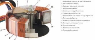
A transformer is an electrical device designed to transmit energy without changing its shape and frequency. Using the phenomenon of electromagnetic induction in its work, the device is used to convert an alternating signal or create galvanic isolation. Each transformer is assembled from the following structural elements:
- core;
- windings;
- frame for winding arrangement;
- insulator;
- additional elements ensuring the rigidity of the device.
The principle of operation of any transformer device is based on the effect of the appearance of a magnetic field around a conductor with an electric current flowing through it. This field also occurs around magnets. Current is the directional flow of electrons or ions (charges). By taking a wire conductor and winding it around a coil and connecting a potential measuring device to its ends, you can observe a surge in the voltage amplitude when the coil is placed in a magnetic field. This suggests that when a magnetic field is applied to a coil with a wound conductor, an energy source or energy converter is obtained.
In a transformer design, such a coil is called primary or mains. It is designed to create a magnetic field. It is worth noting that such a field must necessarily change in direction and magnitude all the time, that is, be variable.
A classic transformer consists of two coils and a magnetic circuit connecting them. When an alternating signal is applied to the contacts of the primary coil, the resulting magnetic flux is transmitted through the magnetic circuit (core) to the second coil. Thus, the coils are connected by magnetic power lines. According to the rule of electromagnetic induction, when the magnetic field changes, an alternating electromotive force (EMF) is induced in the coil. Therefore, a self-induction emf occurs in the primary coil, and a mutual induction emf occurs in the secondary coil.
The number of turns on the windings determines the amplitude of the signal, and the diameter of the wire determines the greatest current strength. If the turns on the coils are equal, the input signal level will be equal to the output. In the case where the secondary coil has three times as many turns, the amplitude of the output signal will be three times greater than the input - and vice versa.
The heating of the entire device depends on the cross-section of the wire used in the transformer. It is possible to select the correct cross-section using special tables from reference books, but it is easier to use an online transformer calculator.
The ratio of the total magnetic flux to the flux of a single coil sets the strength of the magnetic coupling. To increase it, the windings of the coils are placed on a closed magnetic circuit. It is made from materials with good electromagnetic conductivity, for example, ferrite, alsifer, carbonyl iron. Thus, three circuits arise in the transformer: an electrical circuit - formed by the flow of current in the primary coil, an electromagnetic circuit - forming a magnetic flux, and a second electrical circuit - associated with the appearance of current in the secondary coil when a load is connected to it.
The correct operation of the transformer also depends on the frequency of the signal. The larger it is, the less losses occur during energy transfer. This means that the dimensions of the magnetic circuit depend on its value: the higher the frequency, the smaller the dimensions of the device. Pulse converters are built on this principle, the manufacture of which is associated with development difficulties, so a calculator is often used to calculate a transformer according to the core cross-section, which helps to get rid of manual calculation errors.
How to calculate the wire diameter for any winding?
The thicker the better, but with the condition that it fits into the window of the magnetic circuit. If the window is small, then it is advisable to calculate the current of each wound winding in order to select the optimal wire diameter from those available.
The coil current can be calculated using the formula:
I=P/U
I – winding current,
P – power consumed from this winding,
U is the effective voltage of this winding.
For example, I have a power consumption of 31 watts and all of it will be supplied by the coils “III” and “IV”.
31 / (12.8+12.8) = 1.2 Amperes
The diameter of the wire can be calculated using the formula:
D = 1.13 √(I/j)
D – wire diameter in mm,
I – winding current in Amperes,
j – current density in Ampere/mm².
In this case, the current density can be selected according to the table.
| Transformer design | Current density (A/mm2) at transformer power (W) | ||||
| 5-10 | 10-50 | 50-150 | 150-300 | 300-1000 | |
| Single frame | 3,0-4,0 | 2,5-3,0 | 2,0-2,5 | 1,7-2,0 | 1,4-1,7 |
| Double-frame | 3,5-4,0 | 2,7-3,5 | 2,4-2,7 | 2,0-2,5 | 1,7-2,3 |
| Ring | 4,5-5,0 | 4,0-4,5 | 3,5-4,5 | 3,0-3,5 | 2,5-3,0 |
Example:
The current flowing through the coils “III” and “IV” is 1.2 Amperes.
And I chose the current density - 2.5 A/mm².
1.13√ (1.2 / 2.5) = 0.78 mm
I do not have a wire with a diameter of 0.78 mm, but I do have a wire with a diameter of 1.0 mm. Therefore, just in case, I will calculate whether I have enough space for these coils.
The picture shows two options for the frame design: A – regular, B – sectional.
- Number of turns in one layer.
- Number of layers.
The width of my non-sectional frame is 40mm.
I need to wind 124 turns of 1.0mm wire, which has an insulated diameter of 1.08mm. Two such windings are required.
124 * 1,08 * 1,1 : 40 ≈ 3.68 layers
1,1 - coefficient. In practice, when calculating the fill, you need to add 10–20% to the result obtained. I will wind it carefully, turn to turn, so I added 10%.
It turned out 4 layers of wire with a diameter of 1.08 mm. Although, the last, fourth layer is only a few percent full.
Determine the thickness of the winding:
1,08 * 4 ≈ 4.5 mm
I have a 9mm frame depth at my disposal, which means the winding will fit and there will still be some free space left.
The current of coil “II” is unlikely to be more than – 100mA.
1.13√ (0.1 / 2.5) = 0.23 mm
The diameter of the coil wire “II” is 0.23 mm.
This is a tiny winding in terms of filling the window and can not even be taken into account when there is so much free space left.
Of course, in practice, a radio amateur has a limited choice of wires. If there is no wire of a suitable cross-section, then you can wind the winding with several wires of smaller diameter at once. Just to avoid overflows, you need to wind two, three or even four wires at the same time. Crossflows occur when there are even minor deviations in the length of the windings connected in parallel. At the same time, due to the voltage difference, a current arises that heats the windings and creates unnecessary losses.
Before winding several wires, you first need to calculate the length of the winding wire, and then cut the wire into the required pieces.
The length of the wires will be:
L = p * ω * 1.2
L – wire length,
p – perimeter of the frame in the middle of the winding,
ω – number of turns,
1,2* - coefficient.
* Laying the winding when winding several wires is difficult and tedious, so it is better to play it safe and use this coefficient, which compensates for calculation errors and sloppy laying.
A thick wire must be wound turn by turn, while thinner wires can be wound in bulk. The main thing is that the winding fits into the window of the magnetic circuit.
If the winding is done carefully without damaging the insulation, then no spacers between the layers can be used, since when constructing a medium-power ULF, high voltages are not used. The insulation of the winding wire is designed for voltages of hundreds of volts. The thicker the wire, the higher the breakdown voltage of the wire insulation. A thin wire has an insulation breakdown voltage of about 400 Volts, while a thick wire can reach 2000 Volts.
You can secure the end of the wire with regular thread.
If, when removing the secondary winding, the inter-winding insulation protecting the primary winding is damaged, then it must be restored. Here you can use thick paper or thin cardboard. It is not recommended to use any synthetic materials such as adhesive tape, electrical tape and the like.
If the coil is divided into sections for primary and secondary windings, then you can do without insulating spacers altogether.
Return to top menu
Purpose and functionality
So, what functions does a transformer perform?
- This is a reduction in voltage to the required parameters.
- With its help, the galvanic isolation of the network is reduced.
As for the second function, it is necessary to give explanations. Both windings (primary and secondary) of the current transformer are not directly connected to each other. This means that the resistance of the device, in fact, should be infinite. True, this is an ideal option. The connection of the windings occurs through the magnetic field created by the primary winding. This is such a complex functionality.
How to measure wire diameter.
If you have a micrometer lying around at home, you can use it to measure the diameter of the wire.
It is better to first heat the wire in a match flame and only then remove the weakened insulation with a scalpel. If this is not done, then part of the copper can be removed along with the insulation, which will reduce the accuracy of the measurement, especially for a thin wire.
If you don’t have a micrometer, you can use an ordinary ruler. You need to wind 100 turns of wire around the tip of a screwdriver or another suitable axis, compress the turns with your fingernail and attach the resulting set to a ruler. Dividing the result by 100, we get the diameter of the wire with insulation. You can find out the diameter of the copper wire from the table below.
Example.
I wound 100 turns of wire and got a set length of -39 mm.
39 / 100 = 0.39 mm
Using the table, I determine the diameter of the copper wire - 0.35 mm.
Winding wire data table.
| Diameter without insulation, mm | Copper cross section, mm² | Resistance 1m at 20ºС, Ohm | Permissible load at current density 2A/mm² | Diameter with insulation, mm | Weight 100m with insulation, g |
| 0,03 | 0,0007 | 24,704 | 0,0014 | 0,045 | 0,8 |
| 0,04 | 0,0013 | 13,92 | 0,0026 | 0,055 | 1,3 |
| 0,05 | 0,002 | 9,29 | 0,004 | 0,065 | 1,9 |
| 0,06 | 0,0028 | 6,44 | 0,0057 | 0,075 | 2,7 |
| 0,07 | 0,0039 | 4,73 | 0,0077 | 0,085 | 3,6 |
| 0,08 | 0,005 | 3,63 | 0,0101 | 0,095 | 4,7 |
| 0,09 | 0,0064 | 2,86 | 0,0127 | 0,105 | 5,9 |
| 0,1 | 0,0079 | 2,23 | 0,0157 | 0,12 | 7,3 |
| 0,11 | 0,0095 | 1,85 | 0,019 | 0,13 | 8,8 |
| 0,12 | 0,0113 | 1,55 | 0,0226 | 0,14 | 10,4 |
| 0,13 | 0,0133 | 1,32 | 0,0266 | 0,15 | 12,2 |
| 0,14 | 0,0154 | 1,14 | 0,0308 | 0,16 | 14,1 |
| 0,15 | 0,0177 | 0,99 | 0,0354 | 0,17 | 16,2 |
| 0,16 | 0,0201 | 0,873 | 0,0402 | 0,18 | 18,4 |
| 0,17 | 0,0227 | 0,773 | 0,0454 | 0,19 | 20,8 |
| 0,18 | 0,0255 | 0,688 | 0,051 | 0,2 | 23,3 |
| 0,19 | 0,0284 | 0,618 | 0,0568 | 0,21 | 25,9 |
| 0,2 | 0,0314 | 0,558 | 0,0628 | 0,225 | 28,7 |
| 0,21 | 0,0346 | 0,507 | 0,0692 | 0,235 | 31,6 |
| 0,23 | 0,0416 | 0,423 | 0,0832 | 0,255 | 37,8 |
| 0,25 | 0,0491 | 0,357 | 0,0982 | 0,275 | 44,6 |
| 0,27 | 0,0573 | 0,306 | 0,115 | 0,31 | 52,2 |
| 0,29 | 0,0661 | 0.2bb | 0,132 | 0,33 | 60,1 |
| 0,31 | 0,0755 | 0,233 | 0,151 | 0,35 | 68,9 |
| 0,33 | 0,0855 | 0,205 | 0,171 | 0,37 | 78 |
| 0,35 | 0,0962 | 0,182 | 0,192 | 0,39 | 87,6 |
| 0,38 | 0,1134 | 0,155 | 0,226 | 0,42 | 103 |
| 0,41 | 0,132 | 0,133 | 0,264 | 0,45 | 120 |
| 0,44 | 0,1521 | 0,115 | 0,304 | 0,49 | 138 |
| 0,47 | 0,1735 | 0,101 | 0,346 | 0,52 | 157 |
| 0,49 | 0,1885 | 0,0931 | 0,378 | 0,54 | 171 |
| 0,51 | 0,2043 | 0,0859 | 0,408 | 0,56 | 185 |
| 0,53 | 0,2206 | 0,0795 | 0,441 | 0,58 | 200 |
| 0,55 | 0,2376 | 0,0737 | 0,476 | 0,6 | 216 |
| 0,57 | 0,2552 | 0,0687 | 0,51 | 0,62 | 230 |
| 0,59 | 0,2734 | 0,0641 | 0,547 | 0,64 | 248 |
| 0,62 | 0,3019 | 0,058 | 0,604 | 0,67 | 273 |
| 0,64 | 0,3217 | 0,0545 | 0,644 | 0,69 | 291 |
| 0,67 | 0,3526 | 0,0497 | 0,705 | 0,72 | 319 |
| 0,69 | 0,3739 | 0,0469 | 0,748 | 0,74 | 338 |
| 0,72 | 0,4072 | 0,043 | 0,814 | 0,78 | 367 |
| 0,74 | 0,4301 | 0,0407 | 0,86 | 0,8 | 390 |
| 0,77 | 0,4657 | 0,0376 | 0,93 | 0,83 | 421 |
| 0,8 | 0,5027 | 0,0348 | 1,005 | 0,86 | 455 |
| 0,83 | 0,5411 | 0,0324 | 1,082 | 0,89 | 489 |
| 0.86 | 0,5809 | 0,0301 | 1,16 | 0,92 | 525 |
| 0,9 | 0,6362 | 0,0275 | 1,27 | 0,96 | 574 |
| 0,93 | 0,6793 | 0,0258 | 1,36 | 0,99 | 613 |
| 0,96 | 0,7238 | 0,0242 | 1,45 | 1,02 | 653 |
| 1 | 0,7854 | 0,0224 | 1,57 | 1,07 | 710 |
| 1,04 | 0,8495 | 0,0206 | 1,7 | 1,12 | 764 |
| 1,08 | 0,9161 | 0,0191 | 1,83 | 1,16 | 827 |
| 1,12 | 0,9852 | 0,0178 | 1,97 | 1,2 | 886 |
| 1,16 | 1,057 | 0,0166 | 2,114 | 1,24 | 953 |
| 1,2 | 1,131 | 0,0155 | 2,26 | 1,28 | 1020 |
| 1,25 | 1,227 | 0,0143 | 2,45 | 1,33 | 1110 |
| 1,3 | 1,327 | 0,0132 | 2,654 | 1,38 | 1190 |
| 1,35 | 1,431 | 0,0123 | 2,86 | 1,43 | 1290 |
| 1,4 | 1,539 | 0,0113 | 3,078 | 1,48 | 1390 |
| 1,45 | 1,651 | 0,0106 | 3,3 | 1,53 | 1490 |
| 1,5 | 1,767 | 0,0098 | 3,534 | 1,58 | 1590 |
| 1,56 | 1,911 | 0,0092 | 3,822 | 1,64 | 1720 |
| 1,62 | 2,061 | 0,0085 | 4,122 | 1,71 | 1850 |
| 1,68 | 2,217 | 0,0079 | 4,433 | 1,77 | 1990 |
| 1,74 | 2,378 | 0,0074 | 4,756 | 1,83 | 2140 |
| 1,81 | 2,573 | 0,0068 | 5,146 | 1,9 | 2310 |
| 1,88 | 2,777 | 0,0063 | 5,555 | 1,97 | 2490 |
| 1,95 | 2,987 | 0,0059 | 5,98 | 2,04 | 2680 |
| 2,02 | 3,205 | 0,0055 | 6,409 | 2,12 | 2890 |
| 2,1 | 3,464 | 0,0051 | 6,92 | 2,2 | 3110 |
| 2,26 | 4,012 | 0,0044 | 8,023 | 2,36 | 3620 |
| 2,44 | 4,676 | 0,0037 | 9,352 | 2,54 | 4220 |
Return to top menu
Types of cores
Transformers differ from each other not only in their scope of application, technical characteristics and dimensions, but also in the type of magnetic circuit. A very important parameter affecting the magnitude of the magnetic field, in addition to the turns ratio, is the size of the core. The saturation ability depends on its value. The saturation effect occurs when, as the current in the coil increases, the magnitude of the magnetic flux remains unchanged, i.e., the power does not change. To prevent the saturation effect from occurring, you will need to correctly calculate the volume and cross-section of the core, the size of which determines the power of the transformer. Therefore, the greater the power of the transformer, the larger its core should be.
By design, the core is divided into three main types:
- core;
- armored;
- toroidal.
The core magnetic circuit is a U-shaped or W-shaped structure. It is assembled from rods pulled together by a yoke. To protect the coils from the influence of external electromagnetic forces, armored magnetic circuits are used. Their yoke is located on the outside and covers the rod with the coil. The toroidal type is made of metal strips. Due to their ring design, such cores are the most economically advantageous.
Knowing the shape of the core, it is easy to calculate the power of the transformer. It is found using a simple formula: P=(S/K)*(S/K), where:
- S is the cross-sectional area of the core.
- K is a constant coefficient equal to 1.33.
The area of the core depends on its type, its unit of measurement is a centimeter squared. The result obtained is measured in watts. But in practice, it is often necessary to calculate the core cross-section based on the required power of the transformer: Sc = 1.2√P, cm2. Based on the formulas, we can confirm the conclusion: that the greater the power of the product, the larger the core used.
How to calculate the number of turns of the primary winding?
Yes, until now we have proceeded from the assumption that the primary winding is intact. What to do if it turned out to be torn or burned to the ground?
A broken winding can be unwound, the break restored, and re-wound. But the burnt winding will have to be rewound with a new wire.
Of course, the easiest way is to count the number of turns when removing the primary winding.
If you don’t have a counter, and you, like me, use a device based on a hand drill, then you can calculate the amount of reduction of the drill and count the number of full turns of the drill handle. Until I came across a revolution counter at the market, I did just that.
But, if the winding is severely damaged or does not exist at all, then you can calculate the number of turns using the given formula. This formula is valid for a frequency of 50 Hertz.
ω = 44 / (T * S)
ω – number of turns per volt,
44 – constant coefficient,
T – induction value in Tesla,
S is the cross-section of the magnetic circuit in square centimeters.
Example.
The cross-section of my magnetic circuit is 6.25 cm².
The magnetic core is twisted and armored, so I choose 1.5 T induction.
44 / (1.5 * 6.25) = 4.693 volts/volt
We determine the number of turns of the primary winding taking into account the maximum network voltage:
4.693 * 220 * 1.05 = 1084 vit.
Permissible network voltage deviation accepted in most countries: -10… +5%. Hence the coefficient is 1.05.
The magnitude of induction can be determined from the table.
| Type of magnetic circuit | Magnetic induction max (T) at transformer power (W) | ||||
| 5-15 | 15-50 | 50-150 | 150-300 | 300-1000 | |
| Armor stamped | 1,1-1,3 | 1,3 | 1,3-1,35 | 1,35 | 1,35-1,2 |
| Armor twisted | 1,55 | 1,65 | 1,65 | 1,65 | 1,65 |
| Toroidal twisted | 1,7 | 1,7 | 1,7 | 1,65 | 1,6 |
You should not use the maximum induction value, as it can vary greatly for magnetic cores of different quality.
Return to top menu
Pages 1 2 3 4
July 5, 2010 (20:38) in Power supplies, DIY, Technology
Calculation of a pulse transformer of a push-pull converter
The advantage of push-pull converters is their simplicity and the ability to increase power. In a properly designed push-pull converter, a constant current passes through the winding, so there is no strong core bias. This allows you to use a full magnetization reversal cycle and get maximum power. Since it is performed on a ferrite core, the calculation of the output voltage of the transformer is similar to a conventional toroidal one.
You can simplify the transformer calculation options by using special calculation calculators, which are offered by some online resources. One has only to enter the desired data, and the machine will provide the necessary parameters of the planned electromagnetic device.