The operation of asynchronous electric motors is closely related to the need to limit starting currents to preserve the motors. Limitation of the magnitude of starting currents is carried out during the selection of one or another motor starting circuit. In practice, the following types of engine starting are widely used:
- direct start;
- smooth start;
- star-triangle;
- frequency regulation.
Let us consider each of the above methods of starting an asynchronous electric motor in more detail.
Direct start
What is direct start
As the name suggests, direct starting means that the motor is started by direct connection to the power source at rated voltage. Direct-online starting (DOL) is used for stable power supply to a motor rigidly connected to a drive, such as a pump.
Advantages
Direct starting from the DOL network is the simplest, cheapest and most common starting method. In addition, it produces the smallest temperature rise in the motor during startup compared to all other starting methods. If the incoming current from the network does not have special restrictions, this method is the most preferable.
Power plants in different countries have different rules and regulations; for example, in Denmark, for three-phase electric motors with a locked-rotor current of about 60 A, direct starting from the mains cannot always be used. In such cases, it is obviously necessary to choose other starting methods. Electric motors intended for frequent starts/shutdowns are usually equipped with a control system, which consists of a contactor and an overload protection device (thermal relay).
Flaws
For low-power electric motors that operate without frequent starts/stops, the simplest starting equipment is needed, most often a manually controlled trip unit. Voltage is supplied directly to the motor terminals. For small electric motors, the starting torque will be 150 to 300% of the rated value, while the starting current will be 300 to 800% of the rated value or even higher.
The best manufacturers
The main requirement for a soft starter is reliability and long service life. Therefore, when choosing a specific model, it is important to decide on the most popular manufacturers; their list is given in the table below:
Table 1: Comparison of soft starter manufacturers
| Company name | Brief description of products |
| Schneider Electric | Represents the Altistart line of soft starters, both digital and analogue, with a large number of auxiliary functions. |
| Siemens | One of the best German manufacturers. SCPs from Siemens are highly reliable and have the same cost. |
| ABB | Also one of the best manufacturers, produces soft starters with wide functionality. |
| Carlo Gavazzi | One of the leading Italian manufacturers, it is distinguished by convenient start-up and a simple setup system. |
| Danfoss | It is easy to install and has good functionality for connecting electrical machines of different power. |
Star-delta starting
What is star-delta starting?
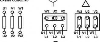
The purpose of this starting method, used for three-phase induction motors, is to reduce the starting current. At the moment of start-up, the power supply to the stator windings is connected in a star (Y) configuration. The power supply switches to delta (Δ) as soon as the motor accelerates.
Advantages
Typically, low voltage motors greater than 3 kW are rated at 400 V in delta (Δ) connection or 690 V in star (Y) connection. This unified connection diagram can also be used to start an electric motor at a lower voltage. The star-delta connection produces a low starting current, only one third of the current for direct line starting. Star-delta starters are particularly suitable for rotating large masses where the load is “caught up” after the rated load speed has been reached.
Flaws
Such starters also reduce the starting torque by approximately 33%. This method can only be used for induction motors that have a delta connection to the supply voltage.
If the star-delta switching occurs at too low a speed, it can cause an overcurrent that reaches almost the same level as the current for direct-on-line starting DOL. During a short period of star-delta switching, the electric motor very quickly loses rotational speed, which also requires a powerful current pulse to restore.
The illustrations on the right show the operation of a Y-D starter. The starter first connects the electric motor in a star configuration (terminals K1 and K3). After a certain period of time, which depends on the specific task, it switches the motor to delta, opening contact K3 and closing contact K2.
Grundfos pumps and motors designated 3 x 380-415 V Δ (but NOT 690 V Y) can be started using star-delta starters, provided the actual motor voltage does not exceed 400 V.
Starting torque and current are significantly lower with star-delta starting than with direct-on-line starting: one third of the current at DOL.
In the example below, the motor is slowly accelerating to approximately 50% of rated speed due to a mismatch between the motor speed vs. torque and the load vs. torque.
About starting three-phase motors, cosine φ and more...
I’ve seen enough videos of turners Mehamozg and Viktor Leontyev on YouTube and I wanted to fulfill my old dream - to also do metal turning. At a local bending enterprise I purchased an old and worn-out 1E61MT machine from 1969.
Inexpensive, almost at the price of scrap metal. There we were also able to purchase a drilling and sharpening machine in a similar condition. So I dragged the whole thing into the garage and the question arose of connecting all this disgrace to electricity. More precisely, this question arose even before the purchase of the machines, several solutions were come up with, and now the time has come to put the ideas into practice.
The machines, like all general industrial equipment, are designed to be connected to a three-phase 380 V network. The lathe consumes the most from this network - about 4.5 kW, most of which is consumed by the asynchronous motor of the main drive. Of course, it will consume maximum power only under the most severe cutting conditions, but still, 2-3 kW is necessary for normal operation. In the garage, there is only a single-phase 220 V network available. Although now you can use the state program and connect 3 phases 15 kW for 550 rubles, but, as people write, there may be problems of an organizational nature that could delay the resolution of the issue indefinitely. Therefore, it was decided to try to make do on our own for now.
The simplest solution today for starting an asynchronous electric motor is to use a frequency converter. In a frequency converter, the original voltage (one or three phases) is rectified to direct current (at least with mandatory correction of the power factor - cosine φ). And then, from direct current using pulse-width modulation, it is generated again, but already three phases, shifted in phase by 120 degrees.
In this case, it is possible to change the voltage and frequency of these phases within certain limits, and, accordingly, change the rotation speed of the asynchronous motor (since in asynchronous motors, the frequency of the supply network directly determines the rotor speed). Thus, you can smoothly accelerate and decelerate the engine and change its speed. This useful property of the frequency converter allows you to even slightly modernize the lathe, throw out the gearbox as unnecessary, significantly simplifying the transmission and thereby reducing the loss of mechanical energy in it, vibration and the overall noise of the machine. The frequency generator is a great thing, but the prices are still steep. Although the Chinese on Aliexpress already offer options within 10 thousand rubles. On Avito, for example, they offer from elevator control stations for 15 - 20 thousand.
But the frequency converter does not solve all problems. Firstly, there are frequency generators for working in single-phase and three-phase networks. Typically, “single-phase” frequency converters are powered by one phase of 220 V and produce 3 phases with a phase-to-phase voltage of also 220 V (that is, for 380/220 delta-connected motors). Accordingly, “three-phase” frequency generators require 3 phases of 380 V for power supply, and also output 3 phases with a phase-to-phase voltage of 380 V. They differ in the voltage that is obtained after rectification and smoothing of the network. In “single-phase” after rectification the voltage is about 310 V, in three-phase - about 530 V. If a three-phase frequency generator is connected to only one phase, it, in principle, will work, but will complain about the low network voltage (310 instead of 530). To deceive him, some suggest changing the values of the resistors in the divider chain (in the diagram above - R1 and R2), with which the frequency controller measures the mains voltage. The divider is recalculated in such a way that when the voltage on the smoothing capacitor is 310 V, the controller thinks that there is 530 V. But this is not an option, since at the output such a frequency generator will still produce phases with an amplitude of the same 310 V, that is, it will require connecting the motor with a triangle, which is not always possible.
A better option is to supply an increased voltage of 380 V (single-phase) to the frequency generator, for example, using a step-up transformer 220/380 V. But, since in this connection option only one phase is rectified, the level of output voltage ripple will be significantly greater than when rectifying 3 phases. Therefore, it is necessary to increase the filter capacity and it is advisable to install a choke if there was none initially, fortunately, many frequency converters have additional terminals specifically for these purposes.
Another option is to remake the input rectifier and filter using a voltage doubling circuit (as is implemented in computer power supplies with a 110/220 V switch). In this case, the rectifier becomes half-wave.
According to this scheme, a voltage of 220 V is supplied to the rectifier diodes and to the midpoint of additional filter capacitors C3, C4, which in this case should have an even larger capacity than in the version with a transformer. The total voltage after such a rectifier becomes 310 + 310 = 620 V, which is already quite close to the threshold at which the frequency driver will begin to complain about excess voltage. This method is applicable for small engine powers, approximately up to 1 kW.
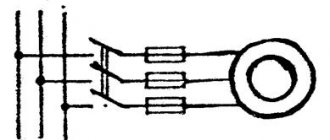
But I have this planned for later (either buy a frequency generator or solder it myself), but for now I decided to do it the old fashioned way. Using starting capacitors. As you know, in inductances and capacitors the phases of voltage and current do not coincide. On inductances, the current phase lags behind the voltage phase, but on capacitance, on the contrary, it leads. Thus, with the help of additional capacitance, you can shift the phase and ensure that the phases on all three terminals of the motor differ by approximately 120 degrees. These circuits have long been known, tables of the required capacitor capacities have long been calculated, they are available both on the Internet and in paper publications. The most commonly used circuit is a starting and working tank. The starting capacitance is connected briefly, only during engine acceleration. The disadvantage of this method is that the maximum engine power is reduced; it is not recommended to load it more than 70% of its maximum power.
Another problem associated with starting an asynchronous motor is that 380 motors are usually connected as a star, the phase-to-phase voltage is 380 V. To be connected to a 220 V network, the windings must be reconnected to a triangle. In this connection, the phase-to-phase voltage of the motor becomes 220 V. If the motor is connected as a 380V star to a 220V network, nothing bad will happen, nothing will burn, the motor will spin, but will not develop the required power, since the voltage on it will be 60% of the nominal. That is, in addition to the fact that the power will drop from working in a single-phase network, the power will also drop from the voltage mismatch, in the end we will get only 20-30% of the rated power. This, of course, is already too little. There is no power reserve, but there should be.
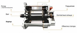
However, very often asynchronous motors are produced without the ability to manually switch the windings in the switching box. For example, all the engines that I came across were exactly like this. 3 wires simply come out of them, connected inside the engine by a star and nothing can be done about it. A long time ago I disassembled one such motor, found the connection point of the three windings inside and brought it out with three separate wires. Everything seemed to work out, the engine started working according to the triangle diagram, but this was still a lot of work. Without the necessary tools and equipment, you can ruin a lot of things. For example, bearings may be skewed, which will then begin to wear out very quickly. And also (almost always) the stator winding is filled with epoxy and, by picking at it, you can easily damage the winding itself.
I decided to do it easier. If it is impossible to reconnect the windings to 220 V, then we have no choice but to increase the voltage to the required 380 V. Turn single-phase 220 V into single-phase 380 V. This can be done using the step-up transformer mentioned above. The only thing is that such a 3-4 kW transformer will be the size of a welding transformer, weigh about the same and, on top of everything else, will cost a pretty penny. If you're lucky enough to find one at all. You can save money here by including a transformer using an autotransformer circuit.
In this case, you need a transformer with an output winding of only 160 V. For the same, for example, 2 kW of output power, the autotransformer will already have to have a power of only 840 W, which is already more or less acceptable. To build the autotransformer, I used transformers from the UPS. They can now be bought very inexpensively, since old 300-500 W UPSs are now being written off en masse, and selling such transformers for copper is not very profitable, since they have a welded magnetic circuit and cannot be disassembled without a grinder. I very successfully purchased 10 of these transformers very inexpensively at one time.
They have a voltage of about 15-16 V on the power winding. If these windings are connected in series in phase, you can get the missing 160 V. If then these 160 V are connected in series in phase with the input voltage of 220 V, we will get the 380 V we need so much.
Another good thing about this method is that you don’t have to worry about replacing starters, local lighting transformers, and other electrical fittings with similar ones, but with a voltage of 220 V. With a step-up transformer, they will work in nominal mode. In general, in a circuit you can generally use some 220 V starters and some 380 V starters, since both voltages are available.
I mounted the transformers in a suitable sized iron box. The front panel displays voltmeters for input and output voltages, an ammeter for the current consumed by the load, and control lights.
The only thing is that not 10, but only 9 transformers fit into the box. I got the missing voltage by connecting 7 low-power 18 volt windings in parallel. All of them together in cross-section become equal to one force. The input of the autotransformer is protected by a double 25 A circuit breaker. One such transformer can power a lathe, drilling machine, as well as other machines that may appear in the future. A voltage of 30 and 45 V is also taken from the transformer taps, which is then rectified and is supposed to be used to brake the main drive motor with direct current. Using the toggle switch, you can select either 30 or 45 V voltage, and the rotor deceleration speed changes accordingly. From the low-power windings of two transformers connected in series, it is supposed to power 36 V LED lamps for local lighting and indication lamps. Here is a sample diagram.
From the same autotransformer it is possible in the future to power electric motors through a frequency converter.
Let's look at the engine starting circuits. For a drilling machine, the circuit is relatively simple.
When you press the “START” button, the starter is activated through one pair of contacts and self-locks, supplying voltage to two phases and through a working capacitor to the third phase. The starting capacitor is connected through another pair of contacts in parallel with the working capacitor. The button must be held down for a split second until the engine spins up. After this, the button can be released. To reverse the direction of rotation, there is a switch; the circuit remains the same, but voltage is supplied to the capacitors from a different wire and the motor begins to spin in the opposite direction. I don’t know why I need to turn the drill in the opposite direction, but since this was the operating logic of the machine initially, I kept it. When the “STOP” button is pressed, the contactor power circuit is broken and the machine is de-energized. There is also a 6 A circuit breaker at the input of the circuit.
The contactor in the diagram is drawn conventionally; in reality, for such a small machine, any very low-power starter, having only three power closing contacts and one low-power one, is sufficient.
To start the engine of a lathe, a similar scheme could be used, except that the starting capacity is required several times larger. That's what I wanted to do at first, with button control. I even purchased a convenient push-button post for this. But then I decided to leave the control from the standard drum switch of the machine. This switch type BP1-153 has three fixed positions “FORWARD”, “STOP” and “BACK”. In the “FORWARD” and “BACKWARD” positions the corresponding pair of contacts is closed. The scheme is something like this:
Each pair of contacts includes its own starter. The starter supplies power to two phases of the motor and through the working capacitance to the third phase. In this version, to change the direction of rotation, instead of changing the location of the capacitor connection, I decided to change the phasing of the power supply on two phases. As mentioned above, it is advisable to turn off the starting tank for the machine after starting it. This can be done, for example, using time relays (DA1 and DA2). After spinning up the engine, the latter becomes a 3-phase generator, from which you can power other consumers that require three-phase power, for example, a coolant pump, which is turned on by a standard package. The “FORWARD” and “BACKWARD” starters are interlocked with normally open contacts. If one is switched on, the switching circuit of the other is broken. When both starters are turned off, the circuit of the fourth starter is closed, which connects a direct current of 30 or 45 V to the two phases of the motor. This starter is turned on briefly, for a split second, to stop the spindle. Short duration is also ensured by a time relay. The circuit of a homemade time relay is shown below and is assembled on the well-known NE555 microcircuit or its analogues.
The connection circuit for the NE555 microcircuit is, in general, typical. The chain of parts R1, VD1, ... VT1, VT2 is necessary to discharge the timing capacitance after the voltage at the relay input is lost.
A few words about the starting capacity. To start the machine engine, you need a sufficiently large capacitance and a sufficiently high voltage, at least 650 V. Collecting such a capacitance from Soviet metal-paper capacitors is not a very good idea, especially if they are not at hand in sufficient quantities. Such a battery will take up a huge amount of space and cost a pretty penny. Modern capacitors are smaller in size, but can also make a big dent in the budget. By the way, you should distinguish between starting and running capacitors. Starters are designed for short-term operation and cannot withstand high reactive power for a long time. They should not be used instead of workers. A very attractive option is to use polar (electrolytic) capacitors. They have high capacity with small dimensions. They can, for example, be installed relatively free of charge on the boards of old tube monitors, televisions and any other equipment that has a switching power supply and a large “network” capacitance after the rectifier. True, their maximum voltage is usually 400 - 450 V, so to work in 380 V circuits I will have to connect 2 of them in series. For example, like this.
To operate on alternating current, such pairs are connected in back-to-back series and are shunted by protective diodes. With a positive half-wave, one capacitor works, with a negative half-wave, another. High-resistance resistors serve to discharge the battery after removing voltage from it and to equalize potentials. This scheme is suitable, for example, for a drilling machine. Here it is assembled.
A lathe requires a significantly larger capacity. When two capacitors are connected in series, the total capacitance is equal to half the capacitance of one capacitor. Therefore, in order to reach the required capacity, we will connect two such chains in parallel. If in the second chain the capacitors are turned in the opposite direction, then a ready-made diode bridge can be used as protective diodes. Approximate diagram.
A very important note for those who want to use such a circuit: this circuit is intended only for short-term operation, only as a starting capacitance. A battery of electrolytic capacitors cannot work for a long time; these capacitors also do not tolerate high reactive power, they heat up and swell.
While selecting the optimal starting and operating capacitance, I noticed an interesting feature - an electromagnetic type ammeter shows the different current consumed by the motor depending on the size of the connected capacitance. In this case, the engine operates with the same constant load. Obviously, the ammeter shows not only the active component of the consumption current, but also the reactive component too. And the reactive component, apparently, is decent. This includes the inductance of the motor, the inductance of electromagnetic starters, and the inductance of a step-up autotransformer.
To study this issue and measure the value of active and reactive power, a Chinese-made device was purchased on Aliexpress. About the same as in the photo.
The device measures and displays the voltage in the network, the current through the load, calculates active and reactive power and cosine φ. The measurement accuracy is stated to be 1% and its own power consumption <0.2 W. The device can be ordered in two versions: for a supply voltage range of 80-300 V and 200-400 V. This is exactly what you need. When I received the device, the first thing that upset me was that instead of the device I ordered for the 200-400 V range, they sent me one for 80-300. After I climbed inside the device to see how it could be converted to 380 V, a second disappointment awaited me: the device itself was powered in the simplest way using a quenching capacitor, a resistor and a zener diode. With a current consumption of 65-70 mA, this meant a power consumption of 20 W at a network voltage of 300 V. Which, of course, is unacceptable. In addition, the use of capacitive ballast introduced errors into the readings of the device itself, albeit relatively small ones. For example, when connecting a 60 W incandescent light bulb (the most active load), the device showed a cosine φ of about 0.909. I experienced the third and greatest disappointment from the product of our Chinese comrades after reading the reviews. In one of the reviews, another buyer reported that in this product the 1st and 2nd digits of the lower indicator are swapped. That is why this device showed such a large cosine φ for a purely active load. This number should actually look like 0.990. It also displayed the power incorrectly. He displayed a power of 20 W as 02 W.
In order for the device to be able to be used somehow, it had to be modified with a file. First, cut the conductors on the board, add jumpers and swap digits 1 and 2 of the lower indicator to correctly display the information. The common cathodes (or anodes) of the indicator are searched for by continuity. Secondly, I threw out all the power circuits from the quenching capacitor up to the internal 3.6 V stabilizer. Instead of the quenching circuit, I used a 5 V switching power supply from a cell phone charger that had long since become unnecessary. If you have the opportunity to choose from several such power sources, you should give preference to branded ones, which are made on a specialized PWM chip and have all the necessary noise filtering elements, rather than no-name ones made haphazardly on a single transistor. It is also necessary to replace the filter tanks on the “hot” side with higher voltage ones, at least 450 V. There are no special requirements for the power of such a power source, since the current consumed by the device does not exceed 100 mA; absolutely any charger can handle such a load. Despite the fact that there is enough free space inside the device to install some particularly small-sized power supply inside the case, I still installed it outside. Firstly, due to the fact that the 450 V filter tanks turned out to be slightly larger than what they were. And secondly, to place this source of interference away from the measuring coil, made on a ferrite ring. The modified device operates stably in the range of 80-270 V, consumes significantly less energy and does not produce an error when measuring cosine φ. When connecting a 60 W incandescent light bulb, the device readings (cosine φ) are now 0.999, that is, as they should be.
Now let’s shed some light on the question of why all this is needed. Because almost all household single-phase meters (all disk meters are 100%) count only active energy. That is, ordinary small consumers are unlikely to have to pay for reagents. Energosbyt forces only large consumers to take into account reactive energy and install total energy meters. But there are a couple of nuances that small consumers should also take into account. Large reactive power traveling through the wires, firstly, leads to heating of these same wires, and this is quite a kind of active power, which is perfectly taken into account by the meter and is then reflected in the payment receipt. If the length of these wires is large, then the losses in them can be significant. Secondly, to reserve reactive power, it is necessary to lay wires of a larger cross-section, which cost a lot of money. If they saved on the wires and laid exactly the same amount as the active power of the consumer, without a current reserve, then the additional reactive power can lead to their heating above the safe level and, also, to large losses of active energy in them. If, for example, a certain consumer consumes active power of 1 kW, but its cosine φ is only, for example, 0.33, then the total power traveling through the wires is 3 times greater! In other words, the wires for such a consumer should be designed for 3 kW. And the losses in the wires will be as much as 3 kW. Accordingly, the switching equipment must also be designed for a power of 3 kW.
In my case, the wires and switching equipment in the garage cooperative have long been laid. Moreover, in ancient times and with the expectation of a couple of Ilyich light bulbs and nothing more, and no one will change them anymore. Therefore, I would not like wires to burn out somewhere in the common panel, other unpleasant things to happen, and then to listen to all sorts of comments from the local electrician and neighbors in the garage.
Let's try to improve the cosine φ using an example with an existing small machine park. The main consumers in it are a drilling machine, a lathe and a sharpening machine. All three machines are powered through the autotransformer described above, which converts a single-phase voltage of 220 V into a single-phase 380 V. First you need to examine the situation, measure this cosine φ, evaluate how good or bad everything is. Maybe the game isn't worth the candle?
Let's connect the meter to the panel, immediately after the meter and the main machine. Thus, the device will measure network parameters at the very cable entrance to the garage. Plugging in incandescent lamps or a soldering iron into the network does not in any way worsen the cosine φ. The device displays 0.999. Turning on all LED and compact fluorescent lighting worsens the cosine φ, but only slightly, to about 0.76.
Indeed, most of them contain a pulse converter with a rectifier and a capacitive filter at the input. Light bulbs create reactivity of a capacitive nature, because connecting a radio receiver with a transformer power supply to the network improves the readings of the cosine φ.
Turning off the light bulbs and turning on the input circuit breaker of the autotransformer (unloaded), we see that the cosine φ sharply drops to a value of 0.5.
Hence the conclusion - the inductance of the transformer is subject to mandatory compensation. When the sharpening machine is turned on, the cosine φ drops to an unacceptably low level - 0.3 - which also needs to be compensated.
But when the drilling machine is turned on, the cosine φ increases slightly - this is the working capacity of the engine starting circuit, which is probably chosen to be slightly larger than required. When the lathe is turned on, the cosine φ remains at a quite acceptable level - 0.95, which means that the working capacity in it is also selected of a sufficient value.
To select a compensating capacitance, we will assemble a battery of several capacitors, each of which can be separately turned on and off with toggle switches.
We will choose capacities in the battery of 4, 6, 20, 40, 64 μF, that is, close to powers of two. Thus, by including different combinations of toggle switches, you can select any capacitance from the range of 4 -134 µF with an approximate step of 4 µF. It feels like this amount of capacitance should be enough to compensate for the existing reactivity. It is clear that it will not be possible to perfectly compensate the cosine φ to 1; for this you need to very accurately select the required capacitance, but this is not required. Let us set ourselves the goal of ensuring a cosine φ of at least 0.95 when turning on any of the existing equipment.
Selecting various combinations of capacitors, it turned out that to compensate for the inductance of the autotransformer, a capacitance of about 5 μF is needed, but I didn’t have one in my kit, so I installed 4 μF there. To compensate for the inductance of the sharpening machine, 24 uF is needed. We also selected a more optimal capacitance for the lathe - 40 uF, with this capacitance the current consumption dropped from 9 to 7 A. I also selected a capacitance for the welding transformer, although for its operating mode this is unlikely to somehow improve the situation, but at least will drive less reactant during downtime. I didn’t touch the drilling machine, everything is fine there. It is better, in my opinion, for small electrical facilities to add a compensating capacitance directly to the device that creates the reactivity. And do not make a general compensator, as is done in large industries. So that when switching on and off consumers you do not have to select a new compensating capacity. Of course, this process can be easily automated by writing a simple program for a microcontroller, if you somehow read information from the meter. But selecting and plugging in the required capacity once is much easier and more reliable (I assume that some on this site will scold me for such a simple approach, without processors and nanotechnological solutions).
By the way, if it is not possible to purchase the φ cosine meter I mentioned or a similar device, you can use any suitable electromagnetic-type panel ammeter. This device shows the total current consumption (active and reactive) and when selecting a compensating capacitance, one should be guided by the minimum readings of the device.
In general, using such simple and relatively simple methods, I was able to start three-phase motors, achieve a good power factor and, probably, some energy savings. The article does not describe anything fundamentally new or innovative, but I think the information will be useful to those who are currently solving a similar problem. Please write comments and suggestions in the comments.
Comparison of DOL and star-delta starting
The following diagrams show the currents for a Grundfos CR pump driven by a 7.5 kW Grundfos MG motor via direct-on-line (DOL) and star-delta starting respectively. As you can see, the DOL starting method is characterized by a high inrush current, which levels off and becomes constant over time. The star-delta starting method has a lower starting current, however, during the starting process, peaks are observed during the transition from star to delta.
When starting according to the “star” circuit (t = 0.3 s), the current decreases. However, during the transition from star to delta (at point t = 1.7 s), the current pulse reaches the same level as the inrush current during direct starting. The current surge may become even larger since no power is supplied to the motor during the switching period. This means that the motor loses speed before applying full voltage (phase voltage).
Start by changing the supply voltage
One of the options for reducing the current load when starting an electric motor is to reduce the supply rating using a constant voltage generator or a controlled rectifier.
From a physical point of view, installing a rheostat provides the same effect, but as the power of the electric motor increases, the constant current load also increases, and losses on the rheostats increase significantly. Therefore, DC voltage reduction is performed by a separate microcircuit-based device, an example of which is shown in the figure below:
Rice. 5. Starting circuit with changing supply voltage
Start via autotransformer
What is autotransformer starting?
As the name implies, such a start is carried out using an autotransformer connected in series with the electric motor during start-up.
Advantages
The autotransformer steps down the voltage (approximately 50-80% of full voltage) to provide low voltage starting. Depending on the specified parameters, the voltage is reduced in one or two stages. Reducing the voltage supplied to the motor at the same time will reduce the starting current and starting torque, but this starting method produces the highest motor torque. If power is not supplied to the electric motor at a certain point in time, it will not lose speed, as is the case with star-delta starting. The switching time from reduced voltage to full voltage can be adjusted.
Flaws
In addition to reducing the starting torque, the starting method through an autotransformer has another drawback. As soon as the electric motor starts running, it switches to mains voltage, which causes a surge in current.
Torque versus voltage
The starting torque values are proportional to the square of the voltage.
Advantages and disadvantages
If we compare synchronous electric motors with asynchronous motors, the former clearly have a more complex mechanism, but we also need to highlight their significant advantages:
- The operation of synchronous motors is not particularly dependent on voltage intensity.
- An important advantage of synchronous motors is their relatively small size, while their efficiency and mechanical functions are much better.
- No matter what the load fluctuations are, it will not affect the revolutions and rotation speed in any way.
- Even in the case of significant overloads on the shaft, the synchronous motor will operate without problems, compensating for such peak surges by increasing the current in the field winding.
- Synchronous motors can operate in the same way as compensators due to the fact that they can produce reactive energy. To do this, you need to apply increased voltage to the excitation winding. If you set the excitation current in the optimal mode, reactive energy will not be consumed, and it will not go to the network.
With all the above advantages of using synchronous electric motors, we must also note one main drawback - the lack of starting torque. That is, to start the engine, it is necessary to use separate equipment.
This is precisely the main reason why synchronous motors have been limited in use for a long time.
Smooth start
Advantages of a soft start
The “soft” start principle is based on semiconductors. Through the energy circuit and the control circuit, these semiconductors lower the initial voltage of the electric motor. This leads to a decrease in the torque of the electric motor. During the starting process, the softstarter gradually increases the motor voltage, which allows the motor to accelerate to its rated speed without generating high torque or current peaks. Soft starters can also be used to control the braking of an electric motor. Soft starters are not as expensive as frequency converters.
Flaws
However, they have the same problems as frequency converters: they can introduce sinusoidal currents (noise) into the system, which can affect its functioning.
This method also ensures that a reduced voltage is supplied to the motor during starting. A soft starter starts the motor at reduced voltage, which then increases to full voltage. The voltage in the soft starter is reduced due to a phase shift. This starting method does not cause current surges. The starting period and starting current can be set.