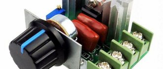
In this tutorial I will show you how to create a simple PWM (Pulse Width Modulation) controller from a 555 chip, a timer and some other components. It's very simple and the NE555's circuitry works well for controlling LEDs, light bulbs, servo motors or DC motors.
My 555 PWM controller can only change the duty cycle from 10% to 90%.
Food for thought
As already mentioned, the 555 timer is a very popular chip. This is because most electronic devices are characterized by periodic processes. Any sound is a periodic process. The PWM signal that controls the motor speed is also periodic, and with a varying duty cycle. And as already mentioned, the operation of any microcontroller and processor is based on a clock signal that has a very precise frequency.
In the next lesson we will make a binary clock using a timer and a binary counter. It will be a little more difficult, but more interesting!
Period and duty cycle of the pulse signal
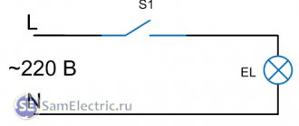
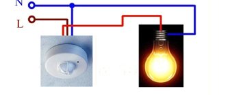
Let's imagine that we are preparing for the New Year and we just need to make a blinking garland. Since we don’t know how to make it blink on its own, we’ll make a garland with a button. We will press the button ourselves, thereby connecting the garland circuit to the power source and causing the light bulbs to light up.
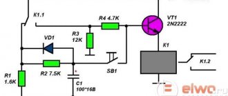
The schematic diagram of a manually controlled garland will look like this:
Generating a pulse signal using a 555 chip
Now let’s try to replace the person and the button, because we don’t want to turn the garland on and off every 3 seconds throughout the holiday.
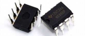
As an automatic pulse generator, we use a very well-known microcircuit of the 555 family. The 555 microcircuit is a generator of single or periodic pulses with specified characteristics. In another way, this class of microcircuits is called timers.
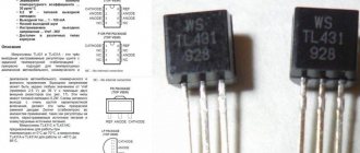
There are different modifications of the 555 timer, developed by different companies: KR1006VI1, NE555, TLC555, TLC551, LMC555. As a rule, they all have the same set of pins.
Manufacturers also distinguish two modes of timer operation: single-shot and multivibrator. The second mode is suitable for us; it is in this mode that the timer will continuously generate pulses with the specified parameters.
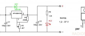
For example, let's connect one LED to the 555 timer. Moreover, we use the option when the positive terminal of the LED is connected to the power supply, and the ground to the timer. Later it will be clear why we do this.
Appearance layout
We assemble the circuit and conduct a small test. Let's try to control the garland according to a simple algorithm:
- press the button;
- wait 1 second;
- release the button;
- wait 2 seconds;
- go to point 1.
This is a batch process algorithm. By pressing the button according to the algorithm, we thereby generate a real pulse signal! Let's depict its time diagram on the graph.
For a given signal, we can determine the repetition period and frequency. The repetition period (T) is the length of time during which the garland returns to its original state. This segment is clearly visible in the figure; it is equal to three seconds. The reciprocal of the repetition period is called the frequency of the periodic signal (F) . The signal frequency is measured in Hertz. In our case:
F = 1/T = 1/3 = 0.33 Hz
The repetition period can be divided into two parts: when the garland is lit and when it is not lit. The length of time during which the garland is lit is called the pulse duration (t) .
Now comes the fun part! The ratio of the repetition period (T) to the pulse duration (t) is called duty cycle .
S = T/t
The duty cycle of our signal is S = 3/1 = 3. The duty cycle is a dimensionless value.
In English-language literature, another term is adopted - duty cycle . This is the reciprocal of the duty cycle.
D=1/S=t/T
In the case of our garland, the fill factor is:
D = 1 / 3 = 0.33(3) ≈ 33%
This option is more clear. D = 33% means that a third of the period is occupied by the impulse. And, for example, with D = 50%, the duration of the high signal level at the timer output will be equal to the duration of the low level.