How to do without a soldering iron
If you don't have a soldering iron, then this is not critical. The described technique is perfect for ordinary headphones without a microphone and control buttons. Unfortunately, it is useless if the cord breaks near the speaker.
Cut off a part of the cable with a connector no shorter than 7 cm, remove the rubber braid with a knife, exposing about 2 cm. You can clean the varnish using sandpaper or a lighter. In order not to damage the wiring, the fire must be extinguished periodically. The carbon deposits can be easily removed with your fingers, but you need to wait until it cools down.
Make an incision a few centimeters above the plug to ensure that the erased area is removed.
Twist all paired wires as tightly as possible. If there are more than three of them, then the two extra ones (responsible for the microphone) can be hidden or cut off, and the sound input will stop working. Sometimes the colors match, but it’s better to check the combination by inserting the connector into the socket of the player with music turned on.
For insulation, use electrical tape, treating each individual pair. After this, they are connected and wrapped in 3-5 layers. You can use wide tape (painting tape will also work) or thin thermal tubes.
Soldering with speaker
Sometimes the contact breaks inside the speaker. In such cases, repairs begin with disassembling the headphones. They try not to shake or tug the device to avoid tearing off the board, inspect the structure and find the damaged area. All broken wires will have to be soldered.
If the cable breaks at the “input” of the earphone, and due to the structure of the case it is impossible to pull it out, then it is better to make a cut at the base. Cut the cord 20 mm from the end of the adapter. It is necessary to remove 80 mm of the thickest insulating layer. Do the same with the internal insulation, but be careful not to touch the wires. Next, the ends are cleaned and tinned according to the standard procedure.
Insert the cord into the housing and unsolder the old wires one by one, soldering new ones in the same places. After soldering is completed, the earphone is assembled and immediately tested for functionality. If the sound is of poor quality or completely absent, then disassemble the case and re-inspect the contacts. The possibility of damage not related to the speakers cannot be ruled out.
Port on motherboard
Most often it is designated AAFP or Front Audio and is located next to the USB connection ports and SATA interfaces. Most motherboard manufacturers place these components in the lower right corner of the part.
p, blockquote 4,0,0,0,0 –>
This port consists of 9 long pins into which special connectors can be inserted. Actually, there should be 10 of them, but the pin with serial number 8, located second from the right in the top row, is missing. The connector going to the front panel does not have a hole in this place.
p, blockquote 5,0,0,0,0 –>
Although these connectors are similar in size to USB, it is impossible to confuse them due to the different positions of the missing plugs.
p, blockquote 6,0,0,0,0 –>
When connecting the front panel, you should carefully place the connectors on the pins without deviations to the left or right, so as not to bend or break them (the latter leads to the fact that it is impossible to use such a port in the future and you will have to be content with the rear audio connectors).
p, blockquote 7,1,0,0,0 –>
Pinout diagrams by manufacturer
Apple audio pinout
iPod Nano (4th, 5th Gen), iPhone (1st, 2nd, 3rd, 4th Gen), iPod Shuffle (3rd Gen), Cell Phone Connection iPhone headphone (handsfree)
Lenovo audio pinouts
1 – left 2 – right 3 – ground 4 – microphone
Lenovo Thinkpad Edge & X Series Notebook audio
Samsung audio pinouts
1 – left 2 – right 3 – ground 4 – microphone
Samsung Galaxy S I9000, S8500 Wave headset EHS60AVNBE / EHS60ANNWEGSTA / EHS60ANNBECSTD/ GH59-09752A headset Samsung Galaxy S2 i9100 headset should be compatible with Samsung Galaxy Note N7000, Samsung Galaxy Tab GT-P1000, P7100 Galaxy Tab 10.1, 4G LTE, C3530 , [ email protected] 350, Galaxy 551 i5510, Galaxy 550 I5500, E2330, I100 Gem, i220 Code, i350 Intrepid, I9003 Galaxy SL, I9100 Galaxy S II, i997 Infuse 4G, Google/Samsung Nexus S I9023/I9020, [email protected ] 335 S3350, Galaxy mini S5570, Wave 525 S5250, Star II S5260, Wave II S8530, S5780 Wave 578, Wave 533 S5330, Galaxy Gio S5660, Wave 723 S7230, Galaxy Ace S5830, Galaxy Fit S5670, Galaxy S 4G, Galaxy S WiFi 5.0 , R910 Galaxy Indulge, S3850 Corby II, M190 Galaxy S Hoppin, M210S Wave2, M220L Galaxy Neo, M580 Replenish, C6712 Star II DUOS
Samsung i300, i330, i500, i700 handsfree/headset connector
Samsung OEM EHS64 Headset for Samsung Galaxy SIII GT-i9305 and some others
Samsung Series 9 Notebook headset (NP900X3D-A02DE)
Samsung SPH-a420, a580, a640, m220, m240, m300, m320, m330, Rant m540, Exclaim m550 SCH-R451C headset Samsung headset P/N: AEP010SLEB/STD
Samsung SPH-A880, SCH-U620, SCH-U540, SPH-M500, SCH-A950, SCH-A870, SCH-A930, SPH-A920, SPH-A940, SCH-A970, SPH-A900 BLADE, A900M, SCH- A990, SCH-U740 AEP204VBEB/STD Headset/Music
In some Samsung models, the ground contact and microphone can be swapped!
Headphone wiring
The most common plug is a 3.5 mini-jack. But besides it, a 2.5 jack is used, as well as miniUSB and mikroUSB.
Wiring for 2.5 and 3.5 jack plugs
There are only three wires in a regular headphone cable. A plug with this number of pins is also called TRS. The numbering goes from tip to cable:
1 - left channel;
2 - right channel;
3 – general.
Instead of three wires, there may be four (two pairs). In this case, one wire from each pair of the same color is considered common and soldered together.
The wiring on such a plug is very simple - the contact ring closest to the cable is common, the remaining ones are the right and left channels. In a standard wiring, the right channel is connected to the middle ring, and the left channel is connected to the end of the plug.
Solder the wires to the appropriate soldering spots. They can be determined visually or with a tester.
The 2.5 plug is designed similarly to the 3.5 and is no different from it except for its size. The wiring is the same on both plugs.
Wiring in miniUSB and miniUSB plugs
In some mobile phones, headphones with a microphone are connected via mini- and mikroUSB connectors. But you can also connect just headphones to these connectors, for example, to use such a mobile phone as an MP3 player.
The wiring in these connectors is the same. They have five pins to which wires are soldered. They are numbered from left to right when viewed from the side where the wires are connected, and the wires are soldered to 1 (common), 3 (right channel) and 4 (left channel).
Wiring in a headset - headphones with a microphone
In addition to regular headphones, which only have speakers, there are headphones with a built-in microphone and control buttons. The cable of such devices has a large number of wires - from four to seven.
Wiring in the 3.5 plug
These plugs have the technical name TRRS. There are two options for wiring these devices OMTP and CTIA. They differ in the connection of the microphone and the common wire, which connect to 3 and 4 wires.
If you connect the wrong type, the microphone will not work and the sound will be muffled.
Electrical methods for determining headset wiring
Unfortunately, it’s not always possible to easily open the control panel and earphone just like that. In such cases, you should use a multimeter.
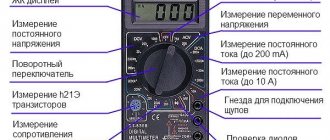
We set the mode as in the picture and poke one probe into the yellow wire, the second probe into the rest. The vast majority of headphones have an impedance of either 16 or 32 ohms. These are standards. In practice, exactly 16 or 32 is rare, usually within +- 3 Ohms, but there are also 10, 24, and 54 Ohms.
The main thing is that the speakers have the same resistance among themselves. So let's say the speakers have a resistance of 32 ohms each. If we grab the ground and one of the channels with the probes of the multimeter, it will show us 32 Ohms. But if one probe is for one channel, and the second for another channel, then it will show the total resistance (in our case 64 ohms), i.e. The speakers in this case are connected in series. If you could not find both speakers, then the wire is broken somewhere further.
Don't have a multimeter? No problem, we'll use a battery. We will need a 1.5 volt tablet. It is better not to use other types of batteries, because... You may burn the speaker coil or damage the cone. I do not recommend keeping the headphones in your ear while identifying channels. It farts very loudly) it’s better to just hang it on your ears, but you can also put it on the table.
The cheeks in the earphone will sound not at the moment when you hold the battery, but when you touch and release it. And you shouldn't hold it for more than a second. It should be light touches.
With these simple methods you can quickly determine which of the wirings is responsible for what. Now I’ll show you a few common options.
Plug types and applications
Depending on the diameter of the working surface, connectors are divided into:
Based on the number of outputs (pin), jacks are divided into:
There are also two types of sockets: regular, created for a specific type of plug, and with a switch - when the pin is inserted, the device switches from one position to another.
Very often there are situations when Chinese collapsible plugs, which were installed instead of a monolithic broken “jack,” do not completely fit into the sleeve or are poorly fixed. Such situations are possible when the diameters of the sleeve and plug do not match. Therefore, when choosing such a plug, it is advisable for you to check its outer diameter with a caliper along the entire working length.
Video.
Related Posts
Normal video card temperature
The cooler on the processor, video card or power supply does not spin or is noisy.
USB plug pinout
for “Pinout of 3.5 mm plug for headphones”
En principio todos y cada uno de los conciertos son Evening With. bracciale rigido uomo cartier imitazione
Good day. I think that such a video could not have been posted. Because apart from music and rhythmic twitching of hands, there is no useful information. You probably forgot why you posted this video. You probably wanted to tell us what the correct pinout is according to the colors of the wires, but you accidentally forgot and got carried away with the dancing of your hands. I give you a like for dancing with your hands and fingers.
on the 4-pin microphone the ground is mixed up in places
Thanks a lot! helped to cope with the low volume in the headphones, I did it according to the first pinout.
Color of wires plus (+) and minus (-) in DC networks
Diode Polarity
Is the red wire positive or negative? Such questions arise when working with DC electrical circuits.
Red
To remember which plus is red or black, they use the name of a well-known international organization - the Red Cross. This phrase suggests that red means plus.
Black
Black color indicates the negative conductor. These markings can be seen on typical household equipment:
- power supplies;
- audio, video equipment;
- other devices with electronic software control units.
Plus
The polarity of conductors must be observed when repairing standard electrical equipment of cars. In some situations, confusion with plus and minus is accompanied by a violation of the functional state.
Minus
The high power of connected consumers increases the responsibility for performing repair and adjustment work. In such situations, it is necessary to eliminate errors in determining polarity. Strong direct current is used to supply electricity:
- warehouse and municipal transport;
- lifting mechanisms;
- sensors and automation.
