What is affected by the number of turns in a transformer?
If we talk about the secondary windings of the transformer, then the value of the number of turns in them mainly affects the output voltage. Things are more complicated with the primary winding, since the voltage on it is set by the supply network. The parameters of the primary winding affect the no-load current, and, consequently, the efficiency. When changing the parameters of the primary winding, it will be necessary to recalculate all secondary windings.
And it is worth noting that it is better not to open the secondary winding of the CT.
Typical parameter calculation
Quite often, radio amateurs use a simplified method when calculating a transformer. It allows you to perform calculations at home without using quantities that are difficult to know. But it’s easier to use an online calculator ready for calculating a transformer. In order to use such a calculator, you will need to know some data, namely:
- voltage of the primary and secondary windings;
- core dimensions;
- plate thickness.
After entering them, you will need to click the “Calculate” button or something similar in name and wait for the result.
Rod type magnetic core
If it is not possible to calculate on a calculator, performing such an operation yourself is not difficult and manually. To do this, you will need to determine the voltage at the output of the secondary winding U2 and the required power Po. The calculation proceeds as follows:
- The load current is calculated: In=Po/U2, A.
- The value of the secondary winding current is calculated: I2 = 1.5*In, A.
- The power of the secondary winding is determined: P2 = U2*I2, W.
- The total power of the device is found: Pt = 1.25*P2, W.
- The current strength of the primary winding is calculated: I1 = Pt/U1, A.
- The required cross-section of the magnetic circuit is found: S = 1.3*√ Pt, cm².
It should be noted that if a device is designed with several terminals in the secondary winding, then in the fourth point all powers are summed up and their result is substituted instead of P2.
After the first stage is completed, proceed to the next stage of calculation. The number of turns in the primary winding is determined by the formula: K1 = 50*U1/S. And the number of turns of the secondary winding is determined by the expression K2= 55* U2/S, where:
- U1 - voltage of the primary winding, V.
- S—core area, cm².
- K1, K2 - number of turns in windings, pcs.
It remains to calculate the diameter of the wound wire. It is equal to D = 0.632*√ I, where:
- d — wire diameter, mm.
- I is the winding current of the calculated coil, A.
When selecting a magnetic core, you should maintain a ratio of 1 to 2 of the width of the core to its thickness. At the end of the calculation, the fillability is checked, i.e. whether the winding will fit on the frame. To do this, the window area is calculated using the formula: So = 50*Pt, mm2.
Calculation method
The full calculation of the transformer is quite complex and takes into account the following parameters:
- supply voltage and frequency;
- number of secondary windings;
- current consumption of each secondary winding;
- type of core material;
- weight and size indicators.
At the household level, for the manufacture of devices powered by a standard 220V 50Hz network, the design can be significantly simplified.
The technique does not require special knowledge of complexity, and if you have experience, it takes little time.
The following data is required for the calculation:
- Number of exits.
- Voltage and current consumption of each winding.
The design of any transformer is based on the total power of all secondary loads:
Pс=I1∙U1+ I2∙U2+… In∙Un
To take into account losses, the concept of overall power has been introduced, for the calculation of which a simple formula is used:
P=1.25∙ Pс
Knowing the power, you can determine the core cross-section:
S=√P
The resulting cross-sectional value will be expressed in square centimeters!
Further calculations depend on the type and material of the selected core. Magnetic cores are of the following types:
- armored;
- rod;
- O-shaped.
The methods for manufacturing magnetic cores also differ:
- typesetting - from individual plates;
- twisted, split or solid.
Armored or rod magnetic cores are usually split, while O-shaped ones are structurally made exclusively in one piece. In this respect, they are no different from continuous rod cores.
To determine the number of turns, use the following ratio, showing how many turns are needed per 1 volt of voltage:
W=K/S,
where K is a coefficient that depends on the material and type of core.
To simplify calculations, the following coefficient values are adopted:
- For stacked magnetic cores made of W- or U-shaped plates K=60.
- For split magnetic cores K=50.
- For O-shaped cores K=40.
As you can see, the shortest length of the winding wire, and therefore the best weight and size indicators, will be for O-shaped cores. In addition, designs with such cores have a small field of parasitic magnetic scattering and maximum efficiency. They are rarely used only because it is technically difficult to wind a winding around a closed core.
Knowing the parameter W, it is easy to determine the number of turns for each winding:
n=U∙W
To take into account the voltage drop on the primary winding, wound with a large amount of thin wire, the number of turns in it should be increased by 5%. This is especially true for small-sized, low-power structures.
You can reduce the no-load current by increasing the W value for each of the windings, but you should be aware that an excessive increase can lead to saturation of the magnetic circuit, which will lead to a sharp increase in the no-load current and a decrease in the output voltage.
At the final stage, the diameter of the conductors of each winding is determined. The calculation formula is as follows:
d=0.7√I
The diameter of the winding wire is determined for all windings without exception.
The resulting values are rounded to the nearest larger standard wire diameter.
Device Description
The inductor can be helical, helical or helical, having a coiled insulated conductor, which has a significant inductance value with a small capacitance with active resistance. As a consequence, the current flows through the current source with significant inertia.
Main component of an electrical circuit
Note! Used to suppress interference, smooth out beats, store energy, limit alternating current or resonant/frequency selective circuit circuits.
It is worth pointing out that its applications are varied. It is called a throttle, variometer, solenoid and current-limiting reactor. However, the main technical characteristics vary. They may differ in current strength, loss resistance, quality factor, capacitance and temperature quality factor.
Full definition from physics
Alternative method for dimensions
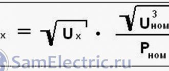
The approximate parameters of the transformer, based on the available core, can be determined in another way, and then conclusions can be drawn about the possibility of further use.
Knowing the cross-sectional area of the magnetic circuit in square centimeters, you can estimate the maximum power that this converter is capable of providing:
PG=S2
It should be borne in mind that this power is dimensional, and the real one will have a smaller value:
P=0.8 PG
Usually, provided that the calculated power matches the required one, the primary winding connected to the 220 V network can be left untouched, recalculating only the parameters at the outputs.
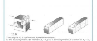
Types of cores
Transformers differ from each other not only in their scope of application, technical characteristics and dimensions, but also in the type of magnetic circuit.
A very important parameter influencing the magnitude of the magnetic field, in addition to the turns ratio, is the size of the core. The saturation ability depends on its value. The saturation effect occurs when, as the current in the coil increases, the magnitude of the magnetic flux remains unchanged, i.e., the power does not change. To prevent the saturation effect from occurring, you will need to correctly calculate the volume and cross-section of the core, the size of which determines the power of the transformer. Therefore, the greater the power of the transformer, the larger its core should be.
By design, the core is divided into three main types:
The core magnetic circuit is a U-shaped or W-shaped structure. It is assembled from rods pulled together by a yoke. To protect the coils from the influence of external electromagnetic forces, armored magnetic circuits are used. Their yoke is located on the outside and covers the rod with the coil. The toroidal type is made of metal strips. Due to their ring design, such cores are the most economically advantageous.
Knowing the shape of the core, it is easy to calculate the power of the transformer. It is found using a simple formula: P=(S/K)*(S/K), where:
- S is the cross-sectional area of the core.
- K is a constant coefficient equal to 1.33.
The area of the core depends on its type, its unit of measurement is a centimeter squared. The result obtained is measured in watts. But in practice, it is often necessary to calculate the core cross-section based on the required power of the transformer: Sc = 1.2√P, cm2. Based on the formulas, we can confirm the conclusion: that the greater the power of the product, the larger the core used.
Using a Multimeter
Using a multimeter, you can find data for recalculating the windings of an existing transformer. To do this, you need to make an additional coil from any available wire. After connecting the device to the network, it is necessary to measure the voltage on the additional coil. Now you can easily calculate the required number of turns per volt and recalculate the transformer to meet the required requirements.
Applications of inductors
Inductors (together with capacitors and/or resistors) are used to construct various circuits with frequency-dependent properties, in particular filters, feedback circuits, oscillatory circuits, etc.
Inductors are used in switching regulators as an element that stores energy and converts voltage levels.
Two or more inductively coupled coils form a transformer.
An inductor, powered by a pulsed current from a transistor switch, is sometimes used as a high-voltage source of low power in low-current circuits when creating a separate high supply voltage in the power supply is impossible or economically impractical. In this case, due to self-induction, high voltage surges appear on the coil, which can be used in the circuit, for example, by rectifying and smoothing.
Coils are also used as electromagnets.
Coils are used as an energy source to excite inductively coupled plasma.
For radio communications - emission and reception of electromagnetic waves (magnetic antenna, ring antenna).
- Loop antenna
- Induction loop
For heating electrically conductive materials in induction furnaces.
As a displacement sensor: the change in the inductance of the coil can be varied over a wide range by moving (pulling out) the core.
The inductor is used in inductive magnetic field sensors. Induction magnetometers were developed and widely used during World War II.
Table of volts per turn
In order not to constantly carry out calculations, you can use the table, which shows the average data of the windings depending on the power:
| Power, P | Section in cm2, S | Number of vit. /B, W | Power, P | Section in cm2, S | Number of vit. /B, W |
| 1 | 1.4 | 32 | 50 | 9.0 | 5.0 |
| 2 | 2.1 | 21 | 60 | 9.8 | 4.6 |
| 5 | 3.6 | 13 | 70 | 10.3 | 4.3 |
| 10 | 4.6 | 9.8 | 80 | 11.0 | 4.1 |
| 15 | 5.5 | 8.4 | 90 | 11.7 | 3.9 |
| 20 | 6.2 | 7.3 | 100 | 12.3 | 3.7 |
| 25 | 6.6 | 6.7 | 120 | 13.4 | 3.4 |
| 30 | 7.3 | 6.2 | 150 | 15.0 | 3.0 |
| 40 | 8.3 | 5.4 | 200 | 17.3 | 2.6 |
How to measure wire diameter.
If you have a micrometer lying around at home, you can use it to measure the diameter of the wire.
It is better to first heat the wire in a match flame and only then remove the weakened insulation with a scalpel. If this is not done, then part of the copper can be removed along with the insulation, which will reduce the accuracy of the measurement, especially for a thin wire.
If you don’t have a micrometer, you can use an ordinary ruler. You need to wind 100 turns of wire around the tip of a screwdriver or another suitable axis, compress the turns with your fingernail and attach the resulting set to a ruler. Dividing the result by 100, we get the diameter of the wire with insulation. You can find out the diameter of the copper wire from the table below.
Example.
I wound 100 turns of wire and got a set length of -39 mm.
39 / 100 = 0.39 mm
Using the table, I determine the diameter of the copper wire - 0.35 mm.
Winding wire data table.
| Diameter without insulation, mm | Copper cross section, mm² | Resistance 1m at 20ºС, Ohm | Permissible load at current density 2A/mm² | Diameter with insulation, mm | Weight 100m with insulation, g |
| 0,03 | 0,0007 | 24,704 | 0,0014 | 0,045 | 0,8 |
| 0,04 | 0,0013 | 13,92 | 0,0026 | 0,055 | 1,3 |
| 0,05 | 0,002 | 9,29 | 0,004 | 0,065 | 1,9 |
| 0,06 | 0,0028 | 6,44 | 0,0057 | 0,075 | 2,7 |
| 0,07 | 0,0039 | 4,73 | 0,0077 | 0,085 | 3,6 |
| 0,08 | 0,005 | 3,63 | 0,0101 | 0,095 | 4,7 |
| 0,09 | 0,0064 | 2,86 | 0,0127 | 0,105 | 5,9 |
| 0,1 | 0,0079 | 2,23 | 0,0157 | 0,12 | 7,3 |
| 0,11 | 0,0095 | 1,85 | 0,019 | 0,13 | 8,8 |
| 0,12 | 0,0113 | 1,55 | 0,0226 | 0,14 | 10,4 |
| 0,13 | 0,0133 | 1,32 | 0,0266 | 0,15 | 12,2 |
| 0,14 | 0,0154 | 1,14 | 0,0308 | 0,16 | 14,1 |
| 0,15 | 0,0177 | 0,99 | 0,0354 | 0,17 | 16,2 |
| 0,16 | 0,0201 | 0,873 | 0,0402 | 0,18 | 18,4 |
| 0,17 | 0,0227 | 0,773 | 0,0454 | 0,19 | 20,8 |
| 0,18 | 0,0255 | 0,688 | 0,051 | 0,2 | 23,3 |
| 0,19 | 0,0284 | 0,618 | 0,0568 | 0,21 | 25,9 |
| 0,2 | 0,0314 | 0,558 | 0,0628 | 0,225 | 28,7 |
| 0,21 | 0,0346 | 0,507 | 0,0692 | 0,235 | 31,6 |
| 0,23 | 0,0416 | 0,423 | 0,0832 | 0,255 | 37,8 |
| 0,25 | 0,0491 | 0,357 | 0,0982 | 0,275 | 44,6 |
| 0,27 | 0,0573 | 0,306 | 0,115 | 0,31 | 52,2 |
| 0,29 | 0,0661 | 0.2bb | 0,132 | 0,33 | 60,1 |
| 0,31 | 0,0755 | 0,233 | 0,151 | 0,35 | 68,9 |
| 0,33 | 0,0855 | 0,205 | 0,171 | 0,37 | 78 |
| 0,35 | 0,0962 | 0,182 | 0,192 | 0,39 | 87,6 |
| 0,38 | 0,1134 | 0,155 | 0,226 | 0,42 | 103 |
| 0,41 | 0,132 | 0,133 | 0,264 | 0,45 | 120 |
| 0,44 | 0,1521 | 0,115 | 0,304 | 0,49 | 138 |
| 0,47 | 0,1735 | 0,101 | 0,346 | 0,52 | 157 |
| 0,49 | 0,1885 | 0,0931 | 0,378 | 0,54 | 171 |
| 0,51 | 0,2043 | 0,0859 | 0,408 | 0,56 | 185 |
| 0,53 | 0,2206 | 0,0795 | 0,441 | 0,58 | 200 |
| 0,55 | 0,2376 | 0,0737 | 0,476 | 0,6 | 216 |
| 0,57 | 0,2552 | 0,0687 | 0,51 | 0,62 | 230 |
| 0,59 | 0,2734 | 0,0641 | 0,547 | 0,64 | 248 |
| 0,62 | 0,3019 | 0,058 | 0,604 | 0,67 | 273 |
| 0,64 | 0,3217 | 0,0545 | 0,644 | 0,69 | 291 |
| 0,67 | 0,3526 | 0,0497 | 0,705 | 0,72 | 319 |
| 0,69 | 0,3739 | 0,0469 | 0,748 | 0,74 | 338 |
| 0,72 | 0,4072 | 0,043 | 0,814 | 0,78 | 367 |
| 0,74 | 0,4301 | 0,0407 | 0,86 | 0,8 | 390 |
| 0,77 | 0,4657 | 0,0376 | 0,93 | 0,83 | 421 |
| 0,8 | 0,5027 | 0,0348 | 1,005 | 0,86 | 455 |
| 0,83 | 0,5411 | 0,0324 | 1,082 | 0,89 | 489 |
| 0.86 | 0,5809 | 0,0301 | 1,16 | 0,92 | 525 |
| 0,9 | 0,6362 | 0,0275 | 1,27 | 0,96 | 574 |
| 0,93 | 0,6793 | 0,0258 | 1,36 | 0,99 | 613 |
| 0,96 | 0,7238 | 0,0242 | 1,45 | 1,02 | 653 |
| 1 | 0,7854 | 0,0224 | 1,57 | 1,07 | 710 |
| 1,04 | 0,8495 | 0,0206 | 1,7 | 1,12 | 764 |
| 1,08 | 0,9161 | 0,0191 | 1,83 | 1,16 | 827 |
| 1,12 | 0,9852 | 0,0178 | 1,97 | 1,2 | 886 |
| 1,16 | 1,057 | 0,0166 | 2,114 | 1,24 | 953 |
| 1,2 | 1,131 | 0,0155 | 2,26 | 1,28 | 1020 |
| 1,25 | 1,227 | 0,0143 | 2,45 | 1,33 | 1110 |
| 1,3 | 1,327 | 0,0132 | 2,654 | 1,38 | 1190 |
| 1,35 | 1,431 | 0,0123 | 2,86 | 1,43 | 1290 |
| 1,4 | 1,539 | 0,0113 | 3,078 | 1,48 | 1390 |
| 1,45 | 1,651 | 0,0106 | 3,3 | 1,53 | 1490 |
| 1,5 | 1,767 | 0,0098 | 3,534 | 1,58 | 1590 |
| 1,56 | 1,911 | 0,0092 | 3,822 | 1,64 | 1720 |
| 1,62 | 2,061 | 0,0085 | 4,122 | 1,71 | 1850 |
| 1,68 | 2,217 | 0,0079 | 4,433 | 1,77 | 1990 |
| 1,74 | 2,378 | 0,0074 | 4,756 | 1,83 | 2140 |
| 1,81 | 2,573 | 0,0068 | 5,146 | 1,9 | 2310 |
| 1,88 | 2,777 | 0,0063 | 5,555 | 1,97 | 2490 |
| 1,95 | 2,987 | 0,0059 | 5,98 | 2,04 | 2680 |
| 2,02 | 3,205 | 0,0055 | 6,409 | 2,12 | 2890 |
| 2,1 | 3,464 | 0,0051 | 6,92 | 2,2 | 3110 |
| 2,26 | 4,012 | 0,0044 | 8,023 | 2,36 | 3620 |
| 2,44 | 4,676 | 0,0037 | 9,352 | 2,54 | 4220 |
Return to top menu
Multi-turn and single-turn coils
What does the inductance of the coil depend on? It is largely related to the number of turns around the core.
A single-turn circuit uses a formula that determines the characteristic in terms of amperage and electromagnetic flux.
It looks like this:
F/I
In multi-turn coils, the same parameter is equal to the square of each turn, because flux linkage increases:
L1 x N2.
To correctly calculate multi-turn coils, geometric parameters and winding type are also taken into account.
Rewinding the stator of an angle grinder: do-it-yourself repair
- 26-01-2015
- 34
- 3560
Wholesale production of hand grinders began in the USSR in 1940. This device received the name “Bulgarian” due to the fact that it was first produced in the small Bulgarian town of Lovech, which had a patent for this invention.
Oblong coils
A type of reel in which the wire is wound onto a pole. To measure it, use the following equation:
Where:
- µe – indicator of magnetic permeability of the medium;
- µi is an indicator of the magnetic permeability of the material;
- i – conductor length;
- r – radius.
Permeability indicators can be found in the table below: