A reversing contactor, which is one of the types of electromagnetic starters. It ensures shaft rotation in both directions, maintains stable operation of motors, turns off power in a timely manner, and protects equipment in emergency situations. Such contactors are an improved example of an electromagnetic starting device and are intended for direct operation with motors. Some models are equipped with additional functions that perform emergency shutdown in case of phase breaks and short circuits.
What is the difference between a magnetic reversing starter circuit: configuration rules
Let's imagine that there is a need to understand the features of a device in which an electric motor is capable of operating in two directions - forward and reverse, that is, reversible. And if such a feature is obvious, it means that the circuit of the unit provides for the presence of a magnetic reversing starter. Its use is not so simple; it is necessary to consider the operating mode in order to prevent dangerous phase short circuits.
In the diagram you can definitely find the designation of an additional control circuit and a reverse start button. Due to such thoughtfulness, the created circuit is reliable, as it is protected from short circuits.
What causes the reverse? This is easy to explain. – Due to the reversal of the two phases present in the system: when one stops working, and the other, on the contrary, starts. For more reliable protection, a blocking must be thought out in the circuit, which is responsible for the accurate and timely stopping of one of the starters, the first or the second. It all depends on the tasks assigned. Let us remind you that if two starters are triggered, a short circuit will instantly occur on the power contacts of the unit.
Note that the reverse movement does not start instantly, since the activation of several important points is required. Firstly, it is definitely recommended to stop the engine and press the “Stop” button
Secondly, you need to pay attention to the condition of the coil, remove the voltage from it, otherwise the reverse starting process will fail. If everything is done correctly, the starter will return to its original position under the action of the spring
That's it, the unit is ready for reverse. We press the “Start” button, accordingly, the required voltage is supplied to the coil, which means the process has started. From the control panel of the device you can read information about the closure of the electrical circuit. This means that current has entered the system, and it is gradually supplied to the coil. At the same time, all contacts that have not started working are blocked. Security requires this.
Please note that if the thermal relay is triggered, the unit will stop to avoid an emergency.
Thus, the magnetic starter plays an important role in the operation of motors. The reversing starter also deserves its place, ensuring uninterrupted operation of machines, heating elements, elevators and other electrical equipment. The starters are reliable and safe, especially if they are additionally equipped with system locking mechanisms. They are located inside the casing and do not allow two coils to operate simultaneously, without leading to a phase short circuit.
{SOURCE}
Differences between reversing and conventional contactor starters
Before considering the differences between both devices, it should be noted that the magnetic starter is an improved version of the contactor, designed to work with low-voltage equipment and installations.
Compared to conventional contactors, magnetic starters are more compact in size and lighter in weight. They are designed for highly specialized actions of turning electric motors on and off. Contactors perform a wider range of tasks in power electrical circuits.
Many starters are additionally equipped with thermal relays that perform emergency shutdowns and protect in case of phase failure. Start-up and shutdown are controlled using special buttons or a separate system consisting of a coil and a low-current contact group. Some modifications may use both options.
Changing Rotational Movement
Now, to give the opposite direction of movement, you need to change the position of the power phases, which is convenient to do using the KM2 switch.
Everything happens thanks to the opening of the first phase. In this case, all contacts return to their original position, de-energizing the motor winding. This phase is the standby mode.
Using the SB3 button activates a magnetic starter with the abbreviation KM2, which, in turn, changes the position of the second and third phases. This action causes the motor to rotate in the opposite direction. Now KM2 is the leader and until it opens, KM1 will not be used.
Basic motor connection diagrams
Before you begin to characterize the reverse of an electric motor, it is necessary to briefly consider the parameters and diagrams of its connection - the base. So, in total, several methods have been implemented for connecting 3-phase asynchronous motors, among which the most popular are:
- star;
- triangle.
The key difference between these schemes is the way the windings are connected to the power supply. In order to determine the existing circuit directly on the engine, you need to familiarize yourself with the data on the technical plate that the manufacturer installs on the motor housing. It is very rare that you need to take any measurements yourself.
When using the “star” method, the operator has the opportunity to ensure a smooth start of the motor, although the power level will be an order of magnitude lower than the nominal values (by approximately 30%). These shortcomings are corrected in the triangle design, which is preferable.
The design of each power unit includes a device called a starter, which in turn comes in two types.
Specifications
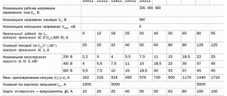
We will not consider all the parameters of the device here, because the choice is always made based on the size of the starter, which is characterized by the rated load current acting on the contacts of the device. There are seven starter values, each of which corresponds to the permissible current load. The photograph below shows these same values and in what areas such magnetic starters are used.
It should be noted that small errors in the parameters are acceptable. But in some cases it is necessary to take into account the range in which the thermal relay operates. If the starters have an overestimated load, and the relays have an underestimated minimum thermal shutdown value, then there may be a mismatch with the specified power of the electrical circuit or consumer.
{SOURCE}
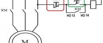
Magnetic starter connection diagrams.
The first, classic scheme, is intended for the usual start of an electric motor: the “Start” button is pressed - the engine turns on, the “Stop” button is pressed - the engine turns off. Moreover, instead of a motor, you can connect any load, for example, a powerful heating element.
For ease of understanding, the circuit is divided into two parts: power part
and
control circuits
.
Power section
powered by three-phase alternating voltage 380V with phases “A” “B” “C”.
The power part includes: three-pole circuit breaker QF1
, three pairs of power contacts of the magnetic starter
1L1-2T1
,
3L2-4T2
,
5L3-6T3
and a three-phase asynchronous electric.
engine M.
_
Control circuit
receives power from phase “A”.
The control circuit diagram includes the SB1
“Stop” button, the
SB2
“Start” button, the magnetic starter coil
KM1
and its auxiliary contact
13NO-14NO
, connected
in parallel with
the “Start” button.
When turning on the QF1
phases “A”, “B”, “C” arrive at the upper contacts of the magnetic starter
1L1
,
3L2
,
5L3
and are on duty there.
Phase “A”, which supplies the control circuits, comes through the “Stop” button to contact No. 3
of the “Start” button, the auxiliary contact of the starter
13NO
and also remains on duty at these two contacts. The circuit is ready for use.
When you press the “Start” button, phase “A” hits the coil of the KM1
, the starter is triggered and all its contacts are closed.
Voltage appears at the lower power contacts 2T1
,
4T2
,
6T3
and from them is supplied to the electrical circuit. engine. The engine starts to rotate.
You can release the "Start" button and the engine will not turn off, since using the auxiliary contact of the starter 13NO-14NO
, connected
in parallel to
the “Start” button,
self-recovery
.
It turns out that after releasing the “Start” button, the phase continues to flow to the coil of the magnetic starter, but through its 13NO-14NO
. In the lower figure, the arrow shows the movement of phase “A”.
And if there is no self-recovery, you will have to keep pressing the “Start” button all the time while the electric power is working. motor or any other load powered by a magnetic starter.
To turn off email. engine, just press the “Stop” button: the circuit will break, the control voltage will stop flowing to the starter coil, the return spring will return the core with the power contacts to its original position, the power contacts will open and disconnect the engine from the three-phase supply voltage.
Now let's look at the editing room
starter control circuit diagram. Here everything is almost the same as in the circuit diagram, with the slight exception of the implementation of self-retaining.
In order not to pull an extra wire to the “Start” button, a jumper is placed between the coil output and one of the nearby auxiliary contacts: in this case it is “ A2
" and "
14NO
".
And from the opposite auxiliary contact the wire runs directly to contact No. 3
of the “Start” button.
Well, you and I have analyzed a simple classic diagram for connecting a magnetic starter. Also, on one starter you can assemble an automatic transfer switch (ATS) circuit, which is designed to ensure uninterrupted power supply to consumers.
Well, if you have any questions or doubts about the operation of the starter, then watch the video, from which you will additionally obtain the necessary information.
The next circuit will be a little more complicated than this one, since it will involve two magnetic starters and three buttons and this circuit is called reversible. Using such a scheme, it will be possible, for example, to rotate the engine left or right, raise and lower the winch.
Until then, goodbye. Good luck!
Type and operation of a 220 V reversible circuit
In this wiring diagram you can see the following main elements (indicated by numbers):
- Blocking or blocking contacts,
- Coils of magnetic starters, designed for a supply voltage of 220 V,
- Thermal or current protection contacts (relay elements),
- Starter power contacts.
Type of reversible circuit for 220 V
In addition, alphanumeric designations distinguish:
- MP-1, MP-2 – magnetic starters. Their boundaries are indicated by dashed lines in the diagram,
- Stop, Start – controls (the block itself is highlighted with a dashed line). Only the Stop button is highlighted separately. Start buttons (forward and reverse) are designated as two pairs of contacts connected to starters MP-1 and MP-2,
- M – electric motor.
Operating principle
As you can see, three opposite phases from the 380 V network are supplied to the power contacts of the starters. There is no designation in the diagram above, but in other cases you can find the symbols A, B, C or L1, L2, L3. A block connection is organized by direct jumper of the central phases of the relay, as well as diagonal jumpers of the side phases (conditionally 1 phase MP-1 is connected to 3 phase MP-2, etc.).
After this, the wires go to the electric motor M. At this interval, a thermal relay is connected to the open circuit. It monitors two of the three phases to cut off power to the motor in the event of an overload.
The control unit with start buttons is connected from one of the central phases to the thermal relay open, and the neutral wire (ground) from the PML starter coils. Protection against simultaneous activation of starters is organized by cross-connecting the contacts of the start/reverse buttons with the blocking contacts of the opposite contactor.
When turned on from the forward control unit, the contacts close to the first starter, which starts the engine. At the same time, the contacts of the second starter open, and the proper voltage does not flow to the coil.
Reverse is turned on after stopping the engine with the Stop button and then pressing reverse. Thus, we have reversed side phases on the coils, which leads to the motor rotating in the opposite direction. Blocking of the first starter occurs according to a similar principle.
Starter capabilities
To limit the starting current of a three-phase motor, its windings can be connected in a star, then, if the motor has reached its rated speed, switch to a delta. In this case, magnetic starters can be: open and in a housing, reversible and non-reversible, with and without overload protection.
Each electromagnetic starter has blocking and power contacts. Power switches loads. Interlocking contacts are needed to control the operation of the contacts. Blocking and power contacts can be naturally open or normally closed. In circuit diagrams, contacts are shown in their normal state.
The ease of use of reversing starters cannot be reviewed. This includes operational control of three-phase asynchronous motors of various machines and pumps, and control of the ventilation system, fittings, right down to the locks and valves of the heating system. The possibility of remote control of starters is especially noteworthy if the electrical source of remote control switches the starter coils in a similar way to relays, and the latter safely connect power circuits.
Starter models
Now let's look at some models of contactors that are used to quickly adjust the operation of motors, including reverse.
PML 2100
Contactor for general industrial use, switches electrical currents. Designed for efficient control of three-phase electric motors with a squirrel-cage rotor. functionality includes:
- launch;
- stop;
- reverse
PML 2100
The PML 2100 magnetic starter for 380 volts has the following parameters:
- current – In – 25A;
- maximum power consumption – 11 kW;
- IP20 – protection level;
- durability – 1 million operating cycles;
- screw mounting or DIN rail mounting.
PML 1100
The operating voltage of the device is 220V AC, 2 variations are implemented: reversible and non-reversible. One of the simplest modifications is designed for 10 amperes; the power also varies depending on the version. You can install coils for 380V, additional break contacts.
PML 1500
The contactor is reversible, has 3 poles. The rated current level (for category AC3) is 10 amperes. Electromagnetic control coil, degree of protection IP00. Working life – 1.5 million cycles.
More about deadlock
The electrical circuit for reversing starting of an asynchronous motor requires an interlock. It is worth understanding that to change the direction of rotation of an asynchronous motor, you need to swap any 2 phases. To do this, the starter inputs are connected directly, and the output is connected crosswise across any 2 phases. If both starters are turned on at the same time, a short circuit will occur, which will most likely burn out the power contact groups on the starters.
You may be interested in: Boyle-Mariotte Law: formula and example problem
In order to avoid a short circuit when installing a reversible motor start, it is necessary to prevent the simultaneous operation of both starters. This is why it is necessary to use an interlocking scheme. When the first starter is turned on, the power to the second starter is interrupted, which prevents its accidental activation, for example, both “start” buttons are pressed simultaneously.
If it turns out that when you press the button that should turn on “rotation to the right,” the engine rotates to the left, and, conversely, when you press “rotation to the left,” the engine rotates to the right, you should not reassemble the entire circuit. Just swap 2 wires at the input - that's all, the problem is solved.
It may happen that this is impossible to do at the input due to some circumstances. In this case, swap the 2 wires in the brand box on the engine. And again the problem is solved. The right spin button will spin right, and the left spin button will spin left.
Description of the operation of the above circuit
You may be interested in: Lictor is: the essence of the profession and historical facts
Let's analyze the operation of the circuit diagram of reverse engine starting. The current flows from phase C to the normally closed common button KnS, the “stop” button. After which it passes through a general current relay, which will protect the engine from overloads. Then, when you press the switch “right”, the current passes through the normally closed contact of the KM2 starter. Entering the coil of the KM1 starter, the core is retracted, closing the power contacts, breaking the power to the KM2 starter.
This must be done in order to interrupt the power supply to the second starter and protect the circuits from short circuits. After all, reverse is ensured by the fact that any 2 phases change places. Thus, if you press the “left” KnP button when KM1 is turned on, the start will not occur. Self-shunting is provided by an auxiliary contact, shown under the “right” control panel. When the starter is turned on, this contact is also closed, providing power to the starter coil.
In order to stop the engine, you must press KnS (“stop”), as a result of which the starter coil will lose power and return to normal. Now that KM1 has returned to its normal state, it has closed the normally closed group of auxiliary contacts, thanks to which the KM2 starter coil can again receive power, and it has become possible to start rotation in the opposite direction. To do this, press the control button “left”, thereby turning on the KM2 starter. Receiving power, the coil draws in the core and closes the power contacts, turning on power to the motor, swapping 2 phases.
Analyzing the operation of this circuit for reversing engine starting, you can notice that the bypass is provided by a normally open auxiliary contact, shown under the “left” switchgear button, and it cuts off the power to the KM1 starter, making it impossible to turn it on.
The circuit for a three-phase drive was discussed above. At the very beginning of the circuit, immediately after the KnS, you can see a normally closed contact from the current relay. If the motor consumes excessive current, the relay is activated, cutting off power to the entire control circuit. Everything that works in the control circuit will lose power, this will save the engine from failure.
Power-up process
The process of turning on the engine is quite simple to describe using the same diagram. The first step is to activate the general switch QF1. As soon as it turns on, voltage is supplied in three phases. But this voltage is not applied directly to the motor itself, since there are still no clear indications in which direction it should rotate. Next, the conductors pass through the SF1 circuit breaker; it performs a protective function, de-energizing the entire system in the event of a short circuit. Next comes the shutdown button, which can also quickly open the power circuit. Only after this does the voltage flow to the SB2 and SB3 keys, after acting on which, the power flows to the engine.
In order for the engine to receive sufficient force for reverse rotation, it is necessary to switch the power phases, which is what the KM2 starter is designed for. If you look at the diagram again, you will notice that the KM1 starter has a direct phase connection to the motor, and KM2 provides some bias. Everything happens at the expense of the first phase, which in this scheme is waiting. As soon as it opens, the voltage supply to the motor is stopped.
After a complete stop, the SB3 button can be activated. It activates the second starter. The latter changes the position of the phases, as shown in the diagram. In this case, the standby phase remains unchanged, power from it is still supplied to the first contact of the motor. Changes occur in the second and third phases. This ensures reverse movement.
General diagram of electric motor reverse
Various types of three-phase asynchronous electric motors are widely used in industry and agriculture. They are installed in electric drives of equipment and serve as an integral part of automatic devices. Three-phase units have gained popularity due to their high reliability, simple maintenance and repair, and the ability to operate directly from the AC mains.
The specific operation of devices operating with electric motors requires a change in the direction of shaft rotation, called reverse. For such situations, special circuits have been developed, which include additional electrical devices. First of all, this is an input machine that has the appropriate parameters, contactors (2 pcs.), a thermal relay and controls in the form of three buttons combined into a common push-button station.
In order for the shaft to start rotating in the opposite direction, it is necessary to change the phase arrangement of the supplied voltage. Constant monitoring of the voltage supplied to the electric motor and contactor coils is necessary. The direct implementation of reverse in a three-phase motor is carried out by contactors (CM) No. 1 and No. 2. When contactor No. 1 is activated, the phases of the incoming voltage will be located differently than when contactor No. 2 is activated.
To control the coils of both contactors, three buttons are provided - FORWARD, BACK and STOP. They provide power to the coils depending on the phase arrangement. The order in which the contactors are turned on affects the closure of the electrical circuit in such a way that the rotation of the motor shaft in each case occurs strictly in a certain direction. The BACK button only needs to be pressed, but not held, since it itself turns out to be in the desired position under the action of self-retaining.
All three buttons are locked to prevent them from being activated at the same time. Failure to comply with this condition may result in a short circuit in the electrical circuit and equipment failure. To block the buttons, a special contact block located in the corresponding contactor is used.
Reversing diagram of a three-phase motor and a push-button station
Each system that provides reverse of a three-phase electric motor has specific push-button contacts combined into a common push-button post. The operation of this system is closely related to the functioning of the remaining elements of the circuit.
Everyone knows that the magnetic starter contactor is turned on using a control pulse received after pressing the start button. This button primarily supplies voltage to the control coil.
The switched-on state of the contactor is maintained and maintained thanks to the self-retaining principle. It consists of connecting in parallel (bypassing) an auxiliary contact to the start button, which supplies voltage to the coil. In this regard, it is no longer necessary to hold the START button pressed. Thus, the magnetic starter can turn off only after the control coil circuit is broken, so the circuit requires a button with a break contact. In this regard, control buttons combined into a push-button station are equipped with two pairs of contacts - normally open (NO) and normally closed (NC).
All buttons are made in a universal version in order to ensure instant reverse of the engine if an urgent need arises. The shutdown button, in accordance with generally accepted standards, is called STOP and is marked in red. The power button is known as the start or start button, so it is referred to variously as START, FORWARD, or REVERSE.
In some cases, a push-button post can be used in a non-reversible electric motor operation scheme, when its shaft rotates in only one direction. The start is made by the start button, and the stop will occur after a certain period of time after pressing the STOP button, when the shaft overcomes the inertia. Connecting such a circuit can be done in two ways, using control coils for 220 and 380 volts.
Operating principle of a reversing magnetic starter
The reversing magnetic starter is connected and operates as follows. After the “start” command is executed on the device’s control panel, the electrical circuit is closed, as a result of which current is supplied to the coil. At this time, the mechanical blocking system is activated, thus blocking unused contacts. Since the contacts of the button are also blocked, this action allows you not to hold the button, but to calmly release it. The second button of the reversing magnetic starter, in parallel with starting the device, opens the circuit, so its activation will not give any result.
To carry out the reverse, it is necessary to activate the “stop” button, pressing which will de-energize both coils of the reversing magnetic starter, thereby stopping the functional operations of the equipment. With this action, all blocking devices will take their original position. This sequence allows you to activate the reversing magnetic starter again, without any additional actions. When you select the “start” command, the above actions will occur, but the second coil will be used, and the first will be blocked.
The most advanced and safe reversing magnetic starter is equipped with additional locking system mechanisms. These devices are placed to block the operating torque, usually inside the casing (directly under the control panel) and are designed to prevent both coils from operating at once. According to the diagram of a reversing magnetic starter, if it is equipped with an electrical interlocking system, then the use of mechanical interlocks is not at all necessary.
Reverse occurs through a complete stop of the engine. In other words, when a reversing magnetic starter is triggered, the motor slows down, followed by a complete stop, and then rotates in the other direction. However, in this case it is necessary to match the power of the engine and the reversible magnetic starter. Only when this process is carried out will the reverse be carried out correctly.
If stopping and reversing the engine is carried out by back switching, then the power of the equipment should be significantly lower than the maximum permissible power of the reversing magnetic starter. Most often, the engine is 1.5-2 times inferior in power to the starter. In many ways, the difference in power depends on the quality of the contacts of the magnetic starter, or rather their wear resistance when operating under these conditions.
This mode must be carried out without the use of mechanical locking systems. However, the safety of operation of a reversing magnetic starter must be ensured by the use of electrical interlocking systems. In general, reversible magnetic starters are a technologically advanced and safe method for remote control of asynchronous electric motors.
What is a magnetic starter, and what is its purpose?
A standard magnetic starter is a typical electromechanical device that is aimed at working with three-phase electric motors. Its intended purpose is to ensure continuous and safe operation of the engine, including control of power supply shutdown to the unit if abnormal or emergency situations occur.
The used circuit of the reversing starter allows it to be successfully used for electric boilers, heating elements, electric motors, that is, when it is necessary to demonstrate the functionality of a switching device or to automatically connect or disconnect from an electrical source.
Let us define the main tasks of the magnetic starter, and they are as follows:
- remote control of units. For example, an asynchronous motor. The created circuit of a reversing starter with buttons allows you to change the direction of rotation of the shaft.
- control of unit loads. Used for unloading low-power contacts. It is even possible to connect a magnetic starter to a home switch, preparing it to handle a large number of light bulbs.
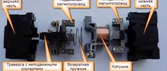
Magnetic starter device for reverse starting
A standard starter consists of the following components:
- a core with an induction coil attached to it;
- anchor with a mechanism for moving contact groups;
- a housing that ensures structural integrity along with protection from external influences.
When the supply current is supplied (switched off), the movement of the armature closes (disconnects) the corresponding contacts of the power circuits. Reversible modifications are created from two conventional starters installed on one mounting panel. Additional conductors provide blocking that prevents two products from being turned on at the same time.
Reversing starter
In this embodiment, separate keys are used that initiate rotation of the rotor in the forward and reverse directions. The first operating mode is accompanied by shunting of the corresponding circuit by the “KM1” contact group. If you press the Back key after this, nothing will happen.
To activate reverse rotation, you must first stop the engine to avoid damage. By pressing “Stop” (C – in the figure below), the supply voltage of 380 V is turned off. Afterwards, you can supply current to the required windings through the power contact groups “KM2”.
Connection diagram
Design and principle of operation
Magnetic contactors or starters refer to switching devices that remotely start electric motors and other equipment. The design and circuit of these devices is very similar to an electromagnetic relay. An important additional function is the ability to promptly connect and disconnect a three-phase load. The main structural element is a magnetic core made in the shape of the letter W. The material used was electrical steel in the form of thin sheets.
The core itself consists of two halves, one of which is stationary and is fixed to the base of the device. The other part - the movable one - in the absence of current is held at a certain distance from the fixed part by a spring. This creates an air gap between both parts.
The starter is controlled through a coil placed on the central rod of the core, located in the stationary part. Contacts are attached to the moving magnetic circuit through a bridge connection. At the moment the starter is triggered, these bridges move simultaneously with the magnetic circuit and make a short circuit with the fixed contact group.
The starting device is triggered after voltage is applied to the control coil. An electromagnetic force arises, under the influence of which the moving part of the core is attracted to the stationary part. As a result, the power contact groups become closed, and current begins to flow to the output terminals. After the voltage supply is stopped, the coil is de-energized and the moving part returns to its place. At this moment, the return spring is activated, ensuring the opening of the contacts.
During switching off, a double gap is formed at each pole of the contacts, facilitating more efficient extinguishing of the electric arc. The function of the arc chute is performed by the device cover, under which the contacts are located.
The starter has not only the main contact group, but also an additional one - in the form of block contacts, used for auxiliary purposes. They are mainly used in control, signaling and blocking circuits.
Protection of power circuits from short circuits or “fool proof”.
As we already know, before changing the rotation of the engine, it must be stopped. But it doesn’t always work out this way, since no one is immune from mistakes. Now imagine a situation where there is no protection.
The engine rotates to the left, starter KM1
in operation and from its output, all three phases go to the windings, each to its own.
Now, without turning off the KM1
, we turn on the
KM2
.
Phases “B” and “C”, which we swapped places for reverse, will meet at the output of the KM1
.
An interphase short circuit
will occur between phases “B” and “C”.
To prevent this from happening, the scheme uses normally closed
starter contacts, which are installed in front of the coils of the same starters, and thus eliminate the possibility of turning on one magnetic starter until the other is de-energized.
How to connect a reversing magnetic starter: diagram, description
In every installation that requires starting an electric motor in forward and reverse directions, there must be a magnetic starter for a reversible circuit. Connecting such a component is not as difficult a task as it seems at first glance. In addition, the demand for such tasks appears quite often. For example, in drilling machines, cutting machines or elevators, if this concerns non-domestic use.
The fundamental difference between this scheme and a single one is the presence of an additional control circuit and a slightly modified power section. Also, to make the switch, this installation is equipped with a button (SB3 in the figure). Such a system is usually short-circuit protected. For this purpose, in front of the coils in the power circuit there are two normally closed contacts (KM1.2 and KM2.2) derived from contact attachments located in the position of the magnetic starters (KM1 and KM2).
In order for the above diagram to be readable, the images of the circuit on it and the power contacts have different colors. Also, for simplicity, pairs of power contacts, which usually have alphanumeric abbreviations, were not indicated here. However, these issues can be found in articles devoted to connecting standard magnetic starting systems.
Reversible motor connection diagram
The direction of rotation of the motor shaft sometimes needs to be changed. This requires a reverse connection diagram. Its type depends on what kind of motor you have: direct or alternating current, 220V or 380V. And the reverse of a three-phase motor connected to a single-phase network is arranged in a completely different way.
Variable network: motor 380 to network 380
To reversibly connect a three-phase asynchronous electric motor, we will take as a basis the circuit diagram for connecting it without reversing:
This scheme allows the shaft to rotate only in one direction - forward. To make it turn into another, you need to swap places of any two phases. But in electrics it is customary to change only A and B, despite the fact that changing A to C and B to C would lead to the same result. Schematically it will look like this:
To connect you will additionally need:
- Magnetic starter (or contactor) – KM2;
- Three-button station, consisting of two normally closed and one normally open contacts (a Start2 button has been added).
The reverse connection scheme differs little from the simple one. Its main difference is the electric locking. It is necessary to prevent the motor from starting in two directions at once, which would lead to breakdown. Structurally, the interlock is a block with magnetic starter terminals that are connected in the control circuit.
To start the engine:
- Turn on the machines AB1 and AB2;
- Press the Start1 (SB1) button to rotate the shaft clockwise or Start2 (SB2) to rotate the shaft in the opposite direction;
- The engine is running.
If you need to change direction, you must first press the “STOP” button. Then turn on another start button. An electrical lock prevents it from being activated unless the motor is switched off.
Variable network: electric motor 220 to network 220
Reversing a 220V electric motor is only possible if the winding terminals are located outside the housing. The figure below shows a single-phase switching circuit, when the starting and working windings are located inside and have no outputs to the outside. If this is your option, you will not be able to change the direction of rotation of the shaft.
In any other case, to reverse a single-phase capacitor IM, it is necessary to change the direction of the working winding. For this you will need:
- Machine;
- Push button post;
- Contactors.
The circuit of a single-phase unit is almost no different from that presented for a three-phase asynchronous motor. Previously, we switched phases: A and B. Now, when changing direction, instead of a phase wire, a neutral wire will be connected on one side of the working winding, and on the other, a phase wire will be connected instead of a zero wire. And vice versa.
Variable network: 380V to 220V
To connect a three-phase asynchronous motor to a 220V power supply, it is necessary to use one or two capacitors to compensate for the missing phase: operating and starting. The direction of rotational movement depends on what the third winding is connected to.
To force the shaft to rotate in the other direction, winding No. 3 must be connected using a capacitor to a toggle switch with two positions. It should have two contacts connected to windings No. 1 and No. 2. Below is a detailed diagram.
Such a motor will play the role of a single-phase motor, since the connection was made using one phase wire.
note
To start it, you need to move the reversing toggle switch to the desired position (“forward” or “backward”), then move the “start” toggle switch to the “on” position.
At the moment of startup, you must press the button of the same name - “start”. You need to hold it for no more than three seconds. This will be enough for overclocking.
Operation of control circuits when the engine rotates to the left.
SB2 button
phase “A” through the normally closed contact
KM2.2
is supplied to the coil of the magnetic starter
KM1
, the starter is triggered and its normally open contacts
close
, and the normally closed contacts
open
.
When contact KM1.1
the starter is
self-retaining
, and when the power contacts
KM1
, phases “A”, “B”, “C” are supplied to the corresponding contacts of the electrical windings. engine and the engine begins to rotate, for example, to the left.
Here, normally closed contact KM1.2
, located in the power circuit of the
KM2
, opens and prevents the
KM2
while the
KM1
. This is the so-called “fool protection”, and more about it below.
The following figure shows the part of the control circuit responsible for the Left command. The circuit is shown using real elements.
Connection diagram for motor reverse using starters
Although the reverse switching of three-phase asynchronous motors is used quite often, nevertheless, ordinary people still ask the question of how to implement it.
As it turned out, the vast majority of asynchronous electric motors, both in everyday life and in production, are connected through magnetic starters.
This is due to the fact that such a connection circuit has fairly good reliability; in addition, protection devices against overload, phase wire breakage and phase imbalance are very easily built into their supply circuits.
note
Simply put, reverse is the rotation of the engine shaft in the opposite direction.
In this article I will look at a diagram for connecting a motor to reverse using a pair of magnetic starters and a three-button remote control.
The version of the scheme given in this article can be considered the simplest. More complex reverse switching schemes may contain several blocking options.
These interlocks can be either electrical or mechanical. The first ones are performed on the buttons that turn on the starters, and the second one is performed on the moving parts of the starters.
The implementation of reverse occurs by changing the phasing of the engine supply voltage.
For example, if you designate the motor power terminals as 1, 2 and 3 (the phase wires of the network are usually designated A, B and C), then when A -> 1, B -> 2 and C -> 3 are connected, the motor shaft will rotate in one direction, and if you connect A -> 1, B -> 3 and C -> 2 - then in the opposite direction.
Such a circuit is implemented, as a rule, using a pair of magnetic starters in such a way that the phasing of the switching on of their power contacts is made so that their sequence differs from each other.
That is, for example, when the first starter is triggered, the motor is connected to phases in the sequence A, B and C, and when the second starter is triggered - A, C and B.
Let's look at the diagram itself (Figure 1). This circuit is made on a pair of magnetic starters KM1 and KM2.
Important
When the first one is triggered (let's assume that it will be KM1), its power contacts are closed, as a result of which the motor windings are energized in the sequence L1, L2, L3.
When the second starter is triggered, the engine will be powered through its contacts, but in phasing L3, L2, L1.
The magnetic starters themselves in this version are connected according to an absolutely standard scheme, with the only difference being that a normally closed block contact of the second starter (KM2.4, KM1.4) is connected to the open circuit of the coil power supply of each of the starters. This is done so that when you press both start buttons, both starters do not trigger.
Picture 1
In addition, the circuit is designed in such a way that a normally open block contact of its starter is connected in parallel with each of the start buttons (KP). This is done so that when the start button is pressed, the starter contactor is self-locking and the button can be released.
The stop button (KS) is included in the open circuit before both starting buttons.
In addition, the circuit has one more contact connected to the open circuit of the supply circuit. This contact is connected to the starter thermal protection device (PT).
This is how such protection works: under excessive loads or (God forbid) phase imbalance, the bimetallic plates of the thermal protection system heat up, as a result of which the latter open the contact associated with them.
Returning this contact to its original state is done using a special red button on the body of the thermal protection device.
Switching reverse without pressing the “stop” button is impossible for the reason that the block contacts of opposite starters included in the circuit will not allow this. This was done for the reason that such a switch can be dangerous for the engine, not to mention the fact that at the moment of rephasing, a phase jump can easily occur.
Advice
For low-power engines, it is possible to perform reverse without pressing the stop button. To do this, it is necessary to make adjustments so that the power group of contacts of one starter opens before the auxiliary normally closed contacts of the second contact close.
Such a switching system is not at all uncommon, but is used very widely for both domestic and industrial purposes. I myself see such a connection quite often for reversing motors of fans, pumps, various machines, conveyors, etc. due to the specifics of my work.
For domestic purposes, reverse switching is used to connect motors of drilling machines, electric mills and meat grinders.
I really hope that the material in my article helped you understand the principles of reverse switching on electric motors using a pair of magnetic starters and now there will be significantly fewer questions on this topic.
Write comments, additions to the article, maybe I missed something. Take a look at the site map, I will be glad if you find anything else useful on my site. All the best.
Source: https://podvi.ru/elektrotexnika/sxema-podklyucheniya-reversa-elektrodvigatelya-s-pomoshhyu-puskatelej.html
VARIETIES OF DEVICES
Models of magnetic starters are classified according to the following parameters:
- operating current switched by the main contacts;
- operating load voltage;
- voltage and type of current of the control coil;
- application category.
The rated currents of the devices comprise a standardized series of values from 6.3 A to 250 A. This series corresponds to the outdated classification of these switching devices by value, according to which all MFs were divided into values from zero (0) to seventh (7).
Each value of the MP value corresponded to a certain rated current. For example, the zero value corresponds to 6.3 amperes, the first - 10 amperes, and so on.
With the advent of a large number of foreign MPs, the prevalence of classification by size began to fade. Indeed, the logic of introducing an additional concept of MF value is difficult to understand. Typical Occam's razor. When choosing a device, we are primarily interested in its rated current, and we should talk about it.
MPs are low-voltage devices designed for connection to networks with voltages up to 1000 volts.
There are two standard voltages in this segment - 380 V and 660 V. What voltage a particular model is designed for is indicated in the technical data sheet of the device, and is also written on the case.
The range of voltages to which the control coil is designed is much more diverse. This is explained by the fact that MPs operate in various control and automation systems.
In this case, the voltage connection to the control coil is not simply from one or two phases of the supply network. In automation systems, special operational current circuits are formed, which vary in voltage level and type of current.
The control coils of switching devices can be designed for connection to alternating voltage in the range from 12 to 660 volts or to direct voltage from 12 to 440 volts.
In accordance with GOST, MPs are divided into 12 categories (from AC–1 to AC–8b), depending on the nature of the AC load they connect. The most common categories are AC-3 and AC-4, intended for connecting squirrel-cage motors.
MPs can also differ in configuration and external design. Common options include models housed in a case with Start and Stop buttons located on the outside. The delivery package of the magnetic starter may include a thermal protection relay.
2012-2020 All rights reserved.
The materials presented on the site are for informational purposes only and cannot be used as guidelines or regulatory documents.
Features of reversing starters
Such connection diagrams are used in the designs of elevators, cranes, and drilling machines. If you don’t go into too much detail, it may seem that the motor switching circuit using reverse is more complicated. But in reality it turns out that there is nothing complicated - another power unit and control have been added to the design.
The cost of such devices is slightly higher due to the use of more elements. Essentially, these are two electromagnetic starters combined into one housing. The operating principle of the circuit is specific; you will need to carefully consider all the nuances.
How to distinguish a reversing starter from a direct one
A reversing starter is a more complex device. In fact, it consists of two conventional direct starters, the latter combined in one housing. The internal circuitry of the reversing device is characterized by the fact that it is impossible to run two modes at the same time - direct and reverse. This process is controlled by a blocking circuit, which can be electrical or mechanical.