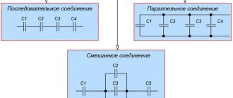
The connection of resistors is the relative position of these elements in the circuit relative to each other and the power source. You can separately select serial and parallel connections of resistors. When both options are present in the circuit, then such a connection is called mixed.
We know that a resistor is an electronic component that has electrical resistance and power dissipation. If there are several resistors in a circuit, then to obtain the total resistance they resort to calculations according to the rules of series or parallel connection. In addition to the general resistance, groups of resistors, according to Ohm's law, affect the voltage and current in sections of the circuit. And in this review, the methodology for calculating the total resistance for various types of resistor connections will be discussed. An illustrative example with a mixed connection of resistors will also be considered, where in addition to resistances, voltages and current strength in different sections will be calculated.
It is worth immediately noting that in this topic the power dissipation of resistors is taken out of the brackets. Power is important when selecting and combining resistors in a circuit, but this is a separate topic. In addition, all the considered examples were taken taking into account a 220 V alternating voltage source. Why is this so? You will learn about this in the last paragraph of the publication.
Series connection of resistors
A series connection of resistors is such a mutual arrangement of components in which the current moves in one direction and has a common value for each resistor. With such a connection, the voltage at each section will be proportional to the resistance of a particular resistor in the circuit.
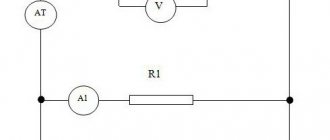
Schematic diagram of serial connection:
As you can see, there are three resistors connected in series in the circuit (there may be more). The resistance of the first resistor R1 = 20 Ohms. Second R2 = 70 Ohm. Third R3 = 10 Ohm.
To calculate the total (equivalent) resistance in a series connection, you need to add up all the nominal resistances of the resistors included in the circuit:
R = R1 + R2 + R3 + … + Rn.
R = 20 + 70 + 10 = 100 Ohm.
For clarity, the presented diagram shows the voltages in each of the three sections. And the voltage drop occurs depending on the resistance of a particular resistor. The current in the circuit is common to all resistors ( I = I1 = I2 = I3 ). Therefore, according to Ohm’s law, the current strength at a known power source voltage (in this case U = 220 V) is determined by the formula:
I = U / R = U / (R1 + R2 + R3 + … + Rn).
I = 220 / (20 + 70 + 10) = 220 / 100 = 2.2 A.
Formulas for finding the voltage on a section of a circuit with a known current strength (in this case I = I1 = I2 = I3 = 2.2 A):
- U1 = I × R1.
- U2 = I × R2.
- U3 = I × R3.
- Un = I × Rn.
Accordingly, U1 = 2.2 × 20 = 44 V; U2 = 2.2 × 70 = 154 V; U3 = 2.2 × 10 = 22 V. As a result, the sum of the potential differences across the resistors is equal to the total potential difference of the entire circuit (220 V).
The three resistors considered in a series circuit can be replaced with one with a resistance of 100 Ohms:
If you can replace several resistors with one, then a logical question arises why such a combination is used. In simple words, we can answer that sometimes it is impossible to select a resistor with the required parameters or it is necessary to create more complex electronic circuits. In this case, they resort to serial, parallel or mixed connection in the circuit.
In a chain of series-connected resistors, the main role is played by the one with the highest resistance. It is this that greatly influences the overall resistance. For example, if you connect three resistors with a nominal value of 1, 10 and 100 ohms, the result will be a composite resistor with a resistance of 111 ohms. If you remove the 100 ohm resistor, the total resistance of the chain drops sharply to 11 ohms. And if you remove the 10 ohm resistor, the resistance decreases slightly to 101 ohms.
Types of consumer connections.
There are serial, parallel and mixed connections of consumers.
When connecting consumers in series, the end of the first consumer is connected to the beginning of the second, the end of the second to the beginning of the third, etc.
Figure 9 – Diagram of serial connection of consumers
1) The current strength is the same for all consumers
2)
The total resistance is equal to the sum of the resistances of individual consumers
3) The voltage at the circuit terminals is equal to the sum of the voltage drops in its individual sections.
If it is necessary to reduce U and I of the receiver, a resistor is connected in series to it.
Conclusion: when one element fails, the entire circuit is de-energized, and when the resistance of one of them changes, the current in the entire circuit and the voltage on each element changes.
When connecting circuit elements in parallel
Figure 10 – Diagram of parallel connection of consumers
1) The total current is equal to the sum of the currents of the parallel branches
2) The voltage on all consumers connected in parallel is the same
3) The total resistance will be less than the smallest one connected in parallel
From Ohm's law for a section of a circuit
—
for two consumers
If the consumer resistances are equal, then
Conclusion:
If one consumer fails, the others remain connected to the circuit.
All receivers are under the same voltage, regardless of their power (resistance).
mixed when the circuit contains both a parallel and a series connection at the same time.
The circuit is gradually simplified, replacing it with equivalent (equal) resistance, using formulas for series and parallel connection of consumers.
Date added: 2017-11-21; ;
Similar articles:
Parallel connection of resistors
A parallel connection of resistors is a mutual connection of components in which both terminals of one resistor are connected to the corresponding terminals of another resistor or resistors.
With this connection, the voltage in the entire circuit and in each section is the same and equal to the voltage of the power source U = U1 = U2 = U3 = Un . Each resistor carries its own current. The sum of the currents of all resistors gives the total current of the circuit: I = I1 + I2 + I3 + ... + In . Accordingly, the total conductivity of a parallel circuit is equal to the sum of its individual conductances. Conductivity is the reciprocal of resistance, so the equivalent resistance of resistors connected in parallel is determined by the following ratio:
1 / R = 1 / R1 + 1 / R2 + 1 / R3 + … + 1 / Rn . The reciprocal value of the total resistance of the circuit is equal to the sum of the reciprocal values of the resistances of parallel-connected conductors.
Let's calculate the total resistance for the above example with parallel connection of resistors:
1/R = 1/20 + 1/70 + 1/10 ≈ 0.164.
R ≈ 1 / 0.164 ≈ 6.097 Ohm.
For clarity, let’s simulate in the Electronics Workbench program the replacement of three parallel-connected resistors with one (R = 6.097 Ohm):
As you can see, the calculation was made correctly, since the current in the circuit with a 6.097 Ohm resistor is equal to the current in the parallel circuit (36.08 A ≈ 36.14 A).
Let us highlight the main features of parallel connection of resistors:
- The total resistance is always less than the resistance of any resistor connected in parallel.
- Increasing the number of resistors connected in parallel leads to a decrease in the total resistance and an increase in the total current in the circuit.
- If two resistors with the same resistance are connected in parallel, then the total resistance of these resistors will be exactly two times less than the resistance of each of the resistors included in this chain.
- If resistors of the same value are used in the circuit, then the formula for the total resistance is simplified and takes the form R = R1 / N (R1 is the nominal resistance of the resistor; N is the number of resistors with the same nominal resistance).
Kirchhoff's first law
As I already mentioned, Kirchhoff’s laws, together with Ohm’s law, are fundamental in the analysis and calculations of electrical circuits. Ohm's law was discussed in detail in the two previous articles, now it is the turn for Kirchhoff's laws. There are only two of them, the first describes the relationship between currents in electrical circuits, and the second describes the relationship between EMF and voltage in the circuit. Let's start with the first one.
Kirchhoff's first law states that the algebraic sum of the currents in a node is equal to zero. This is described by the following expression
where ∑ denotes an algebraic sum.
The word “algebraic” means that the currents must be taken taking into account the sign, that is, the direction of inflow. Thus, all currents that flow into the node are assigned a positive sign, and those flowing out of the node are assigned a correspondingly negative sign. The figure below illustrates Kirchhoff's first law
Image of Kirchhoff's first law.
The figure shows a node into which current flows from the side of resistance R1, and current flows out from the side of resistances R2, R3, R4, then the current equation for this section of the circuit will have the form
Kirchhoff's first law applies not only to nodes, but also to any circuit or part of an electrical circuit. For example, when I talked about parallel connection of energy receivers, where the sum of the currents through R1, R2 and R3 is equal to the inflowing current I.
Mixed connection of resistors
Mixed resistor connection is a combination of series and parallel connection. This combination is sometimes called a series-parallel connection.
Example of a circuit with a mixed connection of resistors:
To calculate the equivalent resistance of such connections, the entire circuit is divided into the simplest sections and the following algorithm is followed:
| The total resistance of sections with parallel connection of resistors is determined. | |
| If these sections contain resistors connected in series, then their total resistance is first calculated. | |
| After intermediate calculations, the circuit is redrawn, and a circuit of equivalent resistances connected in series is obtained. | |
| Next, the resistance of the resulting simple circuit is calculated. |
topological concepts, elements, equivalent circuit
2.Ohm's and Kirchhoff's laws for DC circuits
3.Serial, parallel and mixed connection of consumers
Series, parallel and mixed connections of resistors. A significant number of receivers included in an electrical circuit (electric lamps, electric heating devices, etc.) can be considered as some elements having a certain resistance. This circumstance gives us the opportunity, when drawing up and studying electrical circuits, to replace specific receivers with resistors with certain resistances. There are the following methods of connecting resistors (receivers of electrical energy): serial, parallel and mixed.
Series connection of resistors. When several resistors are connected in series, the end of the first resistor is connected to the beginning of the second, the end of the second to the beginning of the third, etc. With this connection, the same current I passes through all elements of the series circuit. The voltage U at the source terminals is equal to the sum of the voltages at each from series-connected resistors.
Parallel connection of resistors. When several receivers are connected in parallel, they are connected between two points of the electrical circuit, forming parallel branches.
When connected in parallel, the same voltage U is applied to all resistors. Therefore, according to Ohm’s law:
I1=U/R1; I2=U/R2; I3=U/R3.
Current in the unbranched part of the circuit according to Kirchhoff’s first law I = I1+I2+I3,
Mixed connection of resistors. A mixed connection is a connection in which some of the resistors are connected in series, and some in parallel. For example, in the diagram of Fig. 27, and there are two series-connected resistors with resistances R1 and R2, a resistor with resistance R3 is connected in parallel with them, and a resistor with resistance R4 is connected in series with a group of resistors with resistances R1, R2 and R3.
4.Calculation of a DC circuit using the methods of loop currents and nodal potentials
Loop current method. It is based on Kirchhoff's 2nd law. The essence of the method is to maintain fictitious loop currents and calculate them.
1. Determination of the number of equations: y=v-vi.t-(n-1).
B is the number of branches, v.t is the current source, n is the number of nodes.
2. We compose equations for unknown loop currents in general form.
3. Determine the unknown coefficients of the left and right sides (E and R).
4.Substituting the coefficients, we solve the equations and find the circuit currents.
5. We determine the currents in the branches through the loop currents.
Method of nodal potentials. It is based on Kirchhoff's 1st law. We determine the potentials of the circuit nodes, followed by the determination of the currents in the branches, using Ohm's law for sections of the circuit.
1.Preparation of the diagram. Let's designate the nodes. The potential of one of them is taken to be 0.
2. We compose potential equations in general form:
Phi1*g11 + Phi2*g12 = I11 – for the first node
Phi1g21 + Phi*g22 = I22 – for the second node
3. Determine the unknown conductivities gmn – the sum of the conductivities of the branches approaching node n.
4. Substituting, solving the equations, we find phi1 and phi2.
5. We arbitrarily select the directions of the currents and, using Ohm’s law for the circuit section, we determine these currents: In = (phiX-phiY+En)/Rn.
Total resistance Rtotal
With this connection, a separate current will flow through each resistor. The strength of this current will be inversely proportional to the resistance of the resistor. As a result, the total conductivity of such a section of the electrical circuit increases, and the total resistance, in turn, decreases.
Thus, when connecting resistors with different resistances in parallel, the total resistance will always be less than the value of the smallest individual resistor.
Formula for total conductivity when connecting resistors in parallel:
Formula for equivalent total resistance when connecting resistors in parallel:
For two identical resistors, the total resistance will be equal to half of one individual resistor:
Accordingly, for n identical resistors, the total resistance will be equal to the value of one resistor divided by n.
Current flowing in a circuit of parallel connected resistors
For LED current protection, greater care is required when selecting suitable passive elements of the supply circuit. However, only certain values are represented in the series of resistors.
Increasing the budget does not solve the problem. Precision products are produced with minimal tolerances (0.5% or less). But even in this case we are talking about the accuracy of the values. Denominations are offered in accordance with current international standards.
What to do if you need to create a circuit with Rtotal = 11.2 Ohms, if you have serial resistors 11 and 12 Ohms? To obtain the indicated result, a parallel connection is created. The calculation can be done using an online calculator on a specialized website. Calculations are performed automatically after filling out a simple form. Such services are offered free of charge without registration.
Resistor selection table
The reference material presented in the figure will help you select suitable products quickly and accurately. For the example under consideration, resistors of 13 and 82 Ohms are suitable. When installed in parallel, they will create a circuit section resistance of 11.2 ohms.
What is a resistor and what is it for?
A resistor is a radio element that increases the resistance of a circuit. It is usually installed in order to reduce/limit voltage or current. There are constant and variable resistances.
For example, LEDs require little current, otherwise they overheat and quickly fail. To limit the current, place a resistor in front of the LED. The current in the circuit will become less.
What are resistors used for: to adjust power parameters
Constant resistances are those that do not change their value during operation. If this happens, it is considered a failure.
This is what variable and fixed resistors look like
Variable resistors, on the contrary, differ in that their resistance can be changed. They have a slider or rotary knob, with the help of which the denomination changes. Regulators are made on the basis of such devices. For example, volume control, heating element heat control, etc.