The movement of electrons along a conductor encounters a certain obstacle. It depends on the resistivity of the material (ρ) from which the conductor is made, its length (L) and cross-sectional area (S). This physical characteristic was used to create a resistor. It is used to regulate and distribute current in various areas of electrical and electronic circuits. Among other passive elements, this one stands out in that a voltage drop occurs on it and the energy of electricity is converted into heat energy, which is dissipated.
Conductor resistance formula
Types of resistors
A resistor is an inert (passive) circuit element whose resistance can be either constant or variable. It depends on its design. It is used to regulate current and voltage in circuits, power dissipation and other restrictions. The literal translation from English of the word “resistor” is resist.
General view of the elements
Resistors can be classified according to the following criteria:
- purpose of the element;
- type of resistance change;
- material of manufacture;
- type of conductor in the element;
- VAC – current-voltage characteristic;
- installation method.
Devices are divided into general and special purpose elements. Special parts have increased characteristics of resistance, frequency, operating voltage or special requirements for accuracy.
The type of change in resistance divides them into constant and variable. Variable resistors are structurally different not only from elements having a constant resistance, but also from each other. They are different in design: there are adjusting and trimming ones.
Variable type adjusting elements are designed for frequent changes in resistance. This is part of the operation of the device circuit.
The tuning type is designed to fine-tune and adjust the circuit during initial startup. After this, the position of the regulator is not changed.
In the manufacture of resistive bodies (working surfaces), materials such as:
- graphite mixtures;
- metal film (oxide) tapes;
- wire;
- composition components.
Integral elements occupy a special place in this series. These are resistors made in the form of a pn junction, which is a zigzag channel integrated into the chip crystal.
Attention! Integral elements are always characterized by increased nonlinearity of their current-voltage characteristics. Therefore, they are used where the use of other types is not possible.
The type of current-voltage characteristic divides the elements under consideration into linear and nonlinear. The peculiarity of nonlinearity is that the component changes its resistance depending on the following characteristics:
- voltage (varistors);
- temperatures (thermistors);
- magnetic field level (magnetoresistors);
- illumination values (photoresistors);
- strain coefficient (strain gauges).
The nonlinearity of the current-voltage characteristic has expanded the possibilities of their application.
The installation method can be:
- printed;
- mounted;
- integrated.
In printed wiring, the pins of the part are inserted into a hole on the board and then soldered to the panel track. This installation method is automated, and soldering occurs by immersing the contact pads in a bath of solder.
Mounting is mostly done manually. The leads of the parts to be connected are first twisted together and then soldered to improve contact. The soldering itself is not designed to withstand mechanical stress.
Integrated assembly is carried out during the manufacturing process of microcircuit chips.
Resistor element parameters
Current resistance: formula
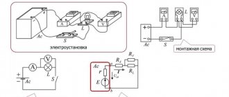
When a graphic designation of a resistance element is applied to a diagram, some of its parameters are indicated on it.
Graphic designation of a resistor on diagrams
The main parameters and elementary characteristics include:
- nominal resistance value;
- temperature coefficient;
- maximum power dissipation;
- permissible operating voltage;
- noise factor;
- relative deviation from nominal value;
- element resistance to high temperature and humidity.
In drawings and diagrams, the resistor is designated by the letter R, followed by its serial number.
Designation of resistors on circuit diagrams.
On circuit diagrams, fixed resistors, regardless of their type, are depicted as a rectangle
, and the resistor terminals are depicted as lines drawn from the sides of the rectangle. This designation is accepted everywhere, but in some foreign circuits the designation of a resistor in the form of a toothed line (saw) is used.
R” is placed next to the symbol
" and the serial number of the resistor in the circuit, and also indicate its nominal resistance in units of Ohm, kOhm, MOhm.
The resistance value from 0 to 999 Ohms is indicated in ohms
, but do not put a unit of measurement:
15
— 15 Ohm
680
– 680 Ohm
920
— 920 Ohm
R is used to denote Ohm
:
1R3
— 1.3 Ohm
33R
– 33 Ohm
470R
— 470 Ohm
Resistance values from 1 to 999 kOhm are indicated in kiloohms
with the addition of the letter "
k
":
1.2k
— 1.2 kOhm
10k
— 10 kOhm
560k
— 560 kOhm
Resistance values of 1000 kOhm and more are indicated in units of megaohm
with the addition of the letter "
M
":
1M
— 1 MΩ
3.3 M
— 3.3 MΩ
56 M
— 56 MΩ
A resistor is used according to the power for which it is designed and which it can withstand without the risk of being damaged when electric current passes through it. Therefore, on the diagrams inside the rectangle, symbols are written indicating the power of the resistor: a double slash indicates a power of 0.125 W; a straight line along the resistor icon indicates a power of 0.5 W; Roman numerals indicate power from 1 W and above.
Resistor calculation
To select and install elements in the circuit, you must first calculate the rating and power of the components.
Formula for calculating resistance and power
Internal resistance - formula
Use Ohm's Law for a section of the circuit to calculate the resistance of the resistor, the formula is:
R = U/I,
Where:
- U – voltage at the terminals of the element, V;
- I – current strength in a section of the circuit, A.
This formula is applicable for currents of constant direction. In the case of calculations for alternating current, the circuit impedance Rz is taken into account.
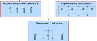
Important! The structure of the circuits is not limited to installing only one resistor. Usually there are many of them, they are connected to each other in parallel and in series. To find the general indicator, separate methods and formulas are used.
Serial connection
With this connection, the “output” of one element is connected to the “input” of another, they go sequentially one after another. How to calculate the resistor in this case? You can use an online electronic calculator, you can apply the formula.
The total value will be the sum of the resistances of the components included in the series connection:
R123 = R1+R2+R3.
Each of them will experience the same voltage drop: U1, U2, U3.
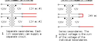
Parallel connection
When performing this type of connection, the terminals of the same name are connected in pairs, the formula looks like:
R = (R1 x R2)/ (R1 + R2).
Usually the resulting R value is less than the smaller of all the values of the connected elements.
Serial and parallel connections
Information. In practice, parallel or series connection is used when there is no part of the required rating. For such cases, elements are selected of the same power and the same type, so as not to get a weak link.
Mixed compound
It is possible to calculate the total resistance of mixed connections by applying the combining rule. First, all parallel and series connections are selected and equivalent equivalent circuits are drawn up. They begin to be calculated using formulas for each case. From the resulting simpler circuit, parallel and serial links are again isolated and calculations are made again. They do this until they get the most elementary compound or one equivalent element. The calculated result will be the desired one.
Calculation method for mixed connection
Power
Finding the resistance value alone is not enough to apply the part. It is necessary to find out what power the element should be designed for. Otherwise, it will overheat and fail. For surface mounting, it is better to install powerful parts on a radiator.
The resistor power is calculated using the formula:
P = I² * R = U²/R,
Where:
- P – power, W;
- I – current, A;
- U – voltage, V;
- R – resistance, Ohm.
After determining the power of the resistors using the formula, components are selected based on the graphic designation on the diagrams.
Basic designations for resistor power
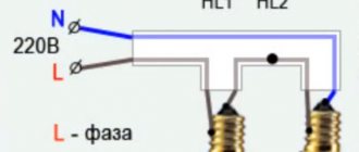
Connection diagram
To ensure that examining the diagram does not cause any particular difficulties, it is better to do this with an example. Therefore, let's talk about what the connection diagram looks like, which is typical for a conventional loudspeaker.
This design is usually equipped with a power amplifier. And this feature directly affects how the connection should be made.
Indeed, in this case, you should connect not two speakers at once, but only one.
Important! If a serial connection type is used, then the same current will necessarily flow through two devices at once.
Voltage divider
The most commonly used ready-made power supplies are designed for output voltages: 9, 12 or 24 volts. At the same time, most electronic circuits and devices use a supply voltage in the range from 3 to 5 V. In this case, there is a need to reduce the value of Upit to the required value. This can be done using a voltage divider, which has many options. The simplest one is a resistor divider.
Divider circuit made using resistors
Resistor power
Such voltage dividers are used exclusively in low-power circuits. This is due to their low efficiency. Some of the power from the power supply is dissipated on the divider, turning into heat. These losses are greater the more you need to reduce the initial voltage. Connecting a load in parallel to one arm requires that Rн be much larger than the resistor installed in this arm. Otherwise, the divider will produce unstable power.
With this scheme, the voltage is distributed over the arms of the divider according to the obtained ratios between R1 and R2. The magnitude of the resistance does not play a role in this case. But it should be remembered that at low values of R1 and R2 both the power at the load and the amount of losses due to heating of the elements increase.
Attention! Before you calculate the exact parameters, you need to remember how to select resistors. If they are equal, the output voltage is divided in half. If equality is not observed, the divided voltage must be removed from the element having a higher rating.
An example of a divider circuit using resistors with small and large values
Current flowing in a circuit of parallel connected resistors
When considering the corresponding sections of branched circuits, it is necessary to remember that the currents at the input and output of each node are equal, as well as before and after the group of parallel resistors. This rule will help check the correctness of the calculations. If the marked correspondence is not met, the calculation error is eliminated.
Using the initial data discussed above for two complex circuits, a calculation can be made for each individual branch.
Example 1:
- the total current in the circuit is 0.8 A;
- the distribution of voltages in individual sections is easy to determine from the calculated equivalent resistances: U12 = I * Req1 = 0.8 * (2*4)/ (2 4) = 0.8 * 1.3 = 1.04 V;
- The current values are calculated using the standard algorithm: I1 = U12/R1 = 0.52 A, I2 = U12/R2 = 0.26 A;
- summation checks the correctness of the calculations: I = I1 I2 = 0.52 0.26 ≈ 0.8 A.
Example 2 (mixed method of connecting resistors):
- current in this version is 1.2 A;
- the voltage in the section with a group of parallel resistors is Uab = I * Reeq(12345) = 1.2*2.5 = 3V;
- By analogy with the previous example, it is easy to calculate the current in each individual branch: I12 = Uav/(R1 R2) = 3/ (15 5) = 0.15 A;
- I3 = Uav/ R3 = 3/ 5 = 0.6 A;
- I4 = Uav/ R4 = 3/ 10 = 0.3 A;
- I5 = Uav/ R5 = 3/20 = 0.15 A;
- According to the rule of equality of currents at the input and output of the node, the correctness of the calculations made is checked: I = I12 I3 I4 I5 = 0.15 0.6 0.3 0.15 = 1.2 A.
READ MORE: Fillers for peat toilets: a comparative review of the best
P = I2 *R = U2/ R.
For your information. The design of each element is designed for a specific operating temperature range. Exceeding the threshold can destroy the part, the soldering point, and neighboring components. One should not forget about a simultaneous significant change in resistance, which can disrupt the functional state of the electrical circuit.
For the calculation, select a suitable formula taking into account the known initial parameters (data from example 2 in the previous section):
- current – 1.2 A;
- at resistance R6=7.5 Ohm the power dissipation will be: P6 = I2 *R = 1.44 * 7.5 = 10.8 W;
- It is difficult to find such a resistor, since the standard range offers ratings from 0.05 to 5 W;
- in another circuit (R5=20 Ohm) the calculated current will be 0.15 A, so P5= 0.0225 * 20 = 0.45 W;
- in this case, you can choose a product with a suitable dissipation power in the standard range of 0.5 W (experts recommend making a 1.52-fold margin, so it is better to use a 1 W resistor).
Standard symbols on electrical diagrams and typical power ratings
For your information. When choosing resistors, you should take into account the product class in terms of electrical resistance accuracy. In serial parts, deviations of 5-20% are acceptable.
Select the appropriate option (combination) taking into account the available initial data. It should be remembered that there is a single voltage at the input and output and different currents in individual branches. Computing technology is discussed in previous sections.
The total current I flowing in a circuit of parallel resistors is equal to the sum of the individual currents flowing in all parallel branches, and the current in a single branch does not necessarily have to be equal to the current in adjacent branches.
Despite the parallel connection, the same voltage is applied to each resistor. And since the value of resistance in a parallel circuit can be different, the amount of current flowing through each resistor will also be different (as defined by Ohm’s law).
Let's consider this using the example of two resistors connected in parallel. The current that flows through each of the resistors (I1 and I2) will be different from each other since the resistances of resistors R1 and R2 are not equal. However, we know that the current that enters the circuit at point "A" must leave the circuit at point " B"
I = I1 I2
Current flowing in R1 = U ÷ R1 = 12 ÷ 22 kOhm = 0.545 mA
Current flowing in R 2 = U ÷ R2 = 12 ÷ 47 kOhm = 0.255 mA
I = 0.545 mA 0.255 mA = 0.8 mA
I = U ÷ R = 12 V ÷ 15 kOhm = 0.8 mA (same)
where 15 kOhm is the total resistance of two parallel connected resistors (22 kOhm and 47 kOhm)
And in conclusion, I would like to note that most modern resistors are marked with colored stripes and their purpose can be found out here.
Dependence of resistance on temperature
The use of resistors as thermometers is due to the almost linear dependence of their resistance on temperature. This applies to those resistors that use wire or metal as the resistive material. Dependency formula:
R = R0+α(t-t0),
- α – temperature coefficient, K-1;
- R0 – conductor resistance at 00K;
- t0 – conductor temperature at 00K.
We are talking about the temperature value in Kelvin. At temperatures approaching zero Kelvin (-273°C), for many metals, when cooled, R abruptly drops to zero. In this case we can talk about superconductivity.
Interesting. Metals that have good conductivity at normal temperatures may not be superconductors at a critical point of this physical quantity. Superconductors in their normal state have a higher resistance than traditional current leads: copper, silver or gold.
When conductors are heated, the change in resistance occurs mainly due to a change in its specific value and has a linear dependence.
Color coding of wirewound resistors
For resistors, color coding is used, which is applied in 3, 4, 5, 6 color rings. If the rings are shifted to one of the terminals, then the ring closest to the terminal is considered to be the first (where decoding of the code begins). If the rings are located approximately evenly, then it should be remembered that the first ring is not made silver or golden. In some models, code reading begins on the side where the paired rings are located; a separate ring is usually located at the end of the cipher.
Color ring decoding table
| Color | Number | Decimal multiplier | Accuracy class, % | Temperature coefficient of resistance | % failure |
| Black | 0 | 1*100 | — | — | — |
| Brown | 1 | 1*101 | 1 | 100 | 1 |
| Red | 2 | 1*102 | 2 | 50 | 0,1 |
| Orange | 3 | 1*103 | — | 15 | 0,01 |
| Yellow | 4 | 1*104 | — | 25 | 0,001 |
| Green | 5 | 1*105 | 0,5 | — | — |
| Blue | 6 | 1*106 | 0,25 | 10 | — |
| Violet | 7 | 1*107 | 0,1 | 5 | — |
| Grey | 8 | 1*108 | 0,05 | — | — |
| White | 9 | 1*109 | — | 1 | — |
| Silver | — | 1*10-2 | 10 | — | — |
| Gold | — | 1*10-1 | 5 | — | — |
In a four-band code, the first two stripes indicate two denomination signs, the third strip is the decimal factor, that is, this is the power to which the number denoting the denomination must be raised. The fourth bar indicates the accuracy class of the element. In a five-line cipher, the third line represents the denomination sign, the fourth the decimal factor, and the fifth the accuracy class. If a sixth band is present, it indicates the temperature coefficient. If this ring is one and a half times wider than the others, then it characterizes the percentage of failures.
Convenient online programs will help you decipher the codes of wirewound resistors. Moreover, it makes sense to turn to them when deciphering the SMD resistor code, since there are several marking options that will be very difficult to figure out on your own.
The magnitude of the voltage provided by the resistor element
The ideal element that converts electricity into another form of energy is called resistive. Electricity can be converted into light, heat or mechanical forms. The voltage across such an element depends on the potential difference at the ends of the resistor. This means that the greater the value of its resistance, the greater the voltage across it.
Changing a resistor characteristic such as resistance makes it possible to implement circuit solutions in various branches of radio engineering and electronics. When selecting elements, one should take into account the specific value of this quantity and the change in the current-voltage characteristic under different operating modes.
Video
Coffee capsule Nescafe Dolce Gusto Cappuccino, 3 packs of 16 capsules
1305 ₽ More details
Coffee capsules Nescafe Dolce Gusto Cappuccino, 8 servings (16 capsules)
435 ₽ More details
Xiaomi Mi smartphones