In electrical circuits, various methods of connecting capacitors are used. The connection of capacitors can be made: series , parallel and series-parallel (the latter is sometimes called a mixed connection of capacitors). Existing types of capacitor connections are shown in Figure 1.
Figure 1. Methods for connecting capacitors.
Serial connection
A capacitor, or in common parlance a “capacity”, is a part that no electrical or electronic board can do without. Even in modern gadgets it is present, albeit in a modified form.
Let us remember what this radio element is. This is a store of electrical charges and energy, 2 conductive plates, between which a dielectric is located. When a DC source is applied to the plates, current will briefly flow through the device and it will charge to the source voltage. Its capacity is used to solve technical problems.
The word itself originated long before the device was invented. The term appeared back when people believed that electricity was some kind of liquid that could be filled with some kind of vessel. In relation to the capacitor, it is unsuccessful, because implies that the device can only accommodate a finite amount of electricity. Although this is not true, the term has remained unchanged.
The larger the plates and the smaller the distance between them, the greater the capacitance of the capacitor. If its plates are connected to any conductor, then a rapid discharge will occur through this conductor.
In coordinated telephone exchanges, with the help of this feature, signals are exchanged between devices. The length of the pulses required for commands, such as: “line connection”, “subscriber answer”, “hang up”, is regulated by the capacitance of the capacitors installed in the circuit.
The unit of measurement for capacitance is 1 Farad. Because Since this is a large value, they use microfarads, picofarads and nanofarads (μF, pF, nF).
In practice, by making a series connection, you can increase the applied voltage. In this case, the applied voltage is received by the 2 outer plates of the assembled system, and the plates located inside are charged using charge distribution. Such methods are resorted to when the necessary elements are not at hand, but there are parts of other voltage ratings.
A section that has 2 capacitors connected in series, rated for 125 V, can be connected to 250 V power.
If for direct current the capacitor is an obstacle due to its dielectric gap, then with alternating current everything is different. For currents of different frequencies, like coils and resistors, the resistance of the capacitor will change. It passes high-frequency currents well, but creates a barrier for their low-frequency counterparts.
Radio amateurs have a way - through a capacitance of 220-500 pF, instead of an antenna, a lighting network with a voltage of 220 V is connected to the radio receiver. It will filter out a current with a frequency of 50 Hz, and let high-frequency currents through. This capacitor resistance can be easily calculated using the formula for capacitance: RC = 1/6*f*C.
Where:
- Rc — capacitance, Ohm;
- f—current frequency, Hz;
- C is the capacitance of this capacitor, F;
- 6 is the number 2π rounded to the nearest integer.
But not only the applied voltage to the circuit can be changed using a similar connection circuit. This is how capacitance changes are achieved in series connections. To make it easier to remember, we came up with a hint that the total capacitance value obtained when choosing such a circuit is always less than the smaller of the two included in the chain.
If you connect 2 parts of the same capacity in this way, then their total value will be half that of each of them. Calculations for series capacitor connections can be made using the formula below:
Commun = C1*C2/C1+C2,
Let C1=110 pF, and C2=220 pF, then Total = 110×220/110+220 = 73 pF.
Do not forget about the simplicity and ease of installation, as well as ensuring high-quality operation of the assembled device or equipment. In series connections, tanks must have 1 manufacturer. And if the parts of the entire chain are from the same production batch, then there will be no problems with the operation of the created chain.
Introduction: I was puzzled.
A few years ago, after over 25 years of working with these things, I learned something new about ceramic capacitors.
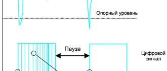
While working on an LED lamp driver, I discovered that the time constant of the RC circuit in my circuit does not closely resemble the calculated one. Assuming that the wrong components were soldered onto the board, I measured the resistance of the two resistors that made up the voltage divider - they were very accurate. Then the capacitor was soldered out - it was also great. Just to be sure, I took new resistors and a capacitor, measured them, and soldered them back in. After that, I turned on the circuit, checked the main indicators, and expected to see that my problem with the RC circuit was solved... If only. I tested the circuit in its natural environment: in a housing, which in turn was itself covered to simulate the casing of a ceiling light. Component temperatures reached more than 100ºC in some places. To be sure and to refresh my memory, I re-read the datasheet for the capacitors used. Thus began my rethinking of ceramic capacitors. Background information on the main types of ceramic capacitors.
For those who don’t remember this (like almost everyone), in Table 1
The marking of the main types of capacitors and its meaning are indicated. This table describes capacitors of the second and third classes. Without going into too much detail, class 1 capacitors are usually made with a C0G (NP0) type dielectric.
Table 1.
| Lower operating temperature | Upper operating temperature | Capacitance change in range (max.) | |||
| Symbol | Temperature (ºC) | Symbol | Temperature (ºC) | Symbol | Change (%) |
| Z | +10 | 2 | +45 | A | ±1.0 |
| Y | -30 | 4 | +65 | B | ±1.5 |
| X | -55 | 5 | +85 | C | ±2.2 |
| – | – | 6 | +105 | D | ±3.3 |
| – | – | 7 | +125 | E | ±4.7 |
| – | – | 8 | +150 | F | ±7.5 |
| – | – | 9 | +200 | P | ±10 |
| – | – | – | – | R | ±15 |
| – | – | – | – | S | ±22 |
| – | – | – | – | T | +22, -33 |
| – | – | – | – | U | +22, -56 |
| – | – | – | – | V | +22, -82 |
Of the ones described above, in my life I most often came across capacitors of the X5R, X7R and Y5V types.
I have never used Y5V type capacitors due to their extremely high sensitivity to external influences. When a capacitor manufacturer develops a new product, it selects the dielectric so that the capacitance of the capacitor does not change more than certain limits over a certain temperature range. The X7R capacitors I use should not change their capacity by more than ±15% (third symbol) when the temperature changes from -55ºC (first symbol) to +125ºC (second symbol). So, either I got a bad batch, or something else is going on in my circuit.
Serial connection diagram
Series connection of capacitors implies that the right leg of each upcoming capacitance will be connected to the left terminal of the next one. In other words, the parts are combined into a chain in which they follow each other, like people in a long line at a store.
If electrolytic capacitors are connected, then the plus of one part is connected to the minus of the other, according to the same principle as batteries in various portable gadgets.
Sequential connection of containers
In the case of SMD parts soldered on the board, each part has its own place; they are connected with thin copper conductors - tracks using a soldering iron (rarely) or a hot air gun.
SMD parts
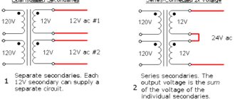
When two or more capacitors are connected in series, their operating voltage is summed up. This approach is often used by radio amateurs when they do not have parts for the required voltage. The formula for calculating the operating voltage of a string of n capacitors is as follows:
Utot.seq = U1 + U2 + … + Un.
Here U1, U2... is the maximum voltage of each individual capacitor.
With the capacity of a line of sequentially connected parts, everything is different. On the contrary, it is decreasing. This is explained by the design features of these devices, namely the virtual increase in the distance between their plates. With a series connection, the total capacitance is determined by the following expression:
1/Ctot.seq = (1/C1) + (1/C2) + … + (1/Cn).
Here C1, C2... are the capacitances of individual capacitors.
There is a simpler calculation for this parameter, but it is only suitable if two capacitors are connected, no more:
Ctotal.seq = C1*C2/(C1 + C2).
Connection of capacitors
Often a capacitor by itself is not enough. Therefore, such electronic components have to be combined into groups, so-called batteries. With this connection, many containers are connected to each other to obtain a new one with different characteristics.
There are 2 main ways to connect parts:
- consistent;
- parallel.
Series connection of containers
With this type of connection, many parts are lined up in a long chain (from two pieces or more). Most often in practice, combinations of 2-5 parts are used. Each previous one is connected to the next one. The result is a long chain, reminiscent of cars on a train.
Serial connection
Connecting capacitors in series reduces their total capacitance. This is due to the fact that the thickness of the dielectric between the plates of the device increases, while the area of their intersection remains unchanged (see formula above). How to calculate the total capacitance of a capacitor when connected in series can be found in the formula below.
Capacitance of series capacitors
In fact, such a connection is used to obtain a new capacitance value, but such a capacitor is simply not commercially available. For example, having two elements with a nominal value of 10 uF each and connecting them in series, you can get a total capacitance of 5 uF.
Example of sequential calculation
Another feature of series connection is the increase in total voltage. If you take 2 containers of 200 V each and connect them in the described way, then the final battery voltage will be 200 + 200 = 400 volts.
Parallel connection
When connecting parts in parallel, all left (conditionally) terminals of the containers are combined into one. It’s the same with the right. If the capacitors are electrolytic, then all the pluses are connected together, as well as all the minuses. The result is a large assembly of parts with only two terminals.
Parallel connection of capacitors
This connection already implies the addition of containers, since the total area of interacting plates increases. In this case, the maximum voltage that can be applied to this battery does not exceed the value of the lowest voltage element. The calculation of the capacitor, namely its capacity, in this case is made using the following expression.
Capacitance of parallel connected capacitors
The method is used when, from many elements with low capacity, you need to get one, but with a high one. An example of using such a connection can be found in a fragment of the diagram of one of the popular welding inverters. It is given below. From the image it can be seen that 6 electrolytic capacitors are used in parallel, which are located immediately after the diode rectifier. Each one is 400V 470uF. As a result, the total capacity of the resulting battery is 470 * 6 = 2820 microfarads. The above calculation can always be performed in a specialized Internet calculator. The peak voltage that is applied to this assembly should not exceed 400 volts. This value is taken with a margin of approximately 30%, because in fact in this unit of the welding machine the effective voltage is 300 V.
Fragment of a welding machine diagram
Additional Information. Capacitors at the input of powerful devices are often used as noise filters and components for reactive power compensation. Such measures can improve the quality of network voltage and protect equipment from short-term power surges.
How to properly connect capacitors
To find out how to connect a capacitor correctly, you need to figure out exactly what type it is. There are a huge variety of these electronic devices. All capacitors are divided into two groups:
- polar (electrolytic) - when connecting them, it is necessary to take into account where the part has a positive and negative contact;
- non-polar (all others) - these capacitors are capable of operating on alternating current; they do not have positive and negative terminals.
Then you need to consider the design of the electronic component. From this point of view, capacitors can be:
- Inferential. They are connected to the board using thin copper legs, coated (tinned) with a layer of solder for protection.
- For surface mounting (SMD). Mainly used in compact electronics. Very miniature, often not exceeding 1 mm in diameter.
It is also important to take into account the operating voltage of the capacitor. This is especially important for electrolytic devices of this type, because if their rated voltage is exceeded, they will most likely explode, spraying boiling electrolyte in all directions.
Important! There are two notches on the cover of the electrolytic capacitor. These weak points serve to instantly depressurize the product in the event of excessive internal pressure. When repairing and adjusting equipment, avoid directing the notches onto your face or clothing. In an emergency, hot electrolyte may splash out from them.
The maximum voltage threshold is no less critical for other types of capacitors, especially those with small dimensions and unable to withstand overloads for a long time.
The last but not least important factor to consider when connecting capacitors is their capacitance. It is measured in microfarads (after Michael Faraday). This is their main characteristic, which is why capacitors are often called electrical capacitances. In some electronic devices, this parameter can deviate significantly, both downward and upward. In others, an error of 1% is unacceptable.
Series connection of capacitors
A series connection of capacitors is used if it is necessary to obtain a capacitance that is less than the capacitance of the element. Such elements can withstand higher voltages. When capacitors are connected in series, the reciprocal of the total capacitance is equal to the sum of the reciprocals of the individual elements. To obtain the required value, certain capacitors are needed, the series connection of which will give the required value.
STUDY OF SERIES, PARALLEL AND MIXED CONNECTION OF CAPACITORS
Goal of the work:
Learn how to assemble capacitor banks and determine their capacity.
Theoretical part
Connecting capacitors in parallel
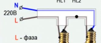
In parallel circuit
connections, all capacitor plates are connected into two groups, with one terminal from each capacitor connected to one group with the others, and the second to another. A clear example of parallel connection and diagram
on the picture
All parallel connected
Capacitors are connected to the same voltage source, so there are two points of potential difference or voltage across them. All terminals of the capacitors will have exactly the same voltage.
When connected in parallel, all capacitors together form fundamentally one capacitance, the value of which will be equal to the sum of all capacitances of the capacitors connected in the circuit. When connected in parallel, a different current will flow through each capacitor, which will depend on the capacitance value of each of them. The higher the capacitance, the more current will flow through it.
Parallel connection
occurs very often in life. With its help, you can assemble any necessary capacitance from a group of capacitors. For example, to start a 3-phase electric motor in a single-phase 220 Volt network, as a result of calculations you received that a working capacity of 125 μF is required. You will not find capacitors of this size on sale. In order to obtain the required capacitance, you will have to buy and connect in parallel 3 capacitors, one for 100 μF, the second for 20, and the third for 5 μF.
Connecting capacitors in series
For serial connection
In capacitors, each plate is connected at only one point to one plate of the other capacitor. This results in a chain of capacitors. The outer two terminals are connected to a current source, resulting in a redistribution of electrical charges between them. The charges on all intermediate plates are the same in magnitude, alternating in sign.
The same amount of current flows through all connected capacitors in series because there is no other path for it to pass. The total capacity
will be limited by the area of the plates of the smallest in size, because as soon as the capacitor with the smallest capacity is fully charged, the entire chain will stop passing current and the charge of the others will be interrupted. It's calculated that I eat
bone according to this formula:
But with consistent
connection, the distance (or insulation) between the plates increases to a value equal to the sum of the distances between the plates of all series-connected capacitors. For example, if you take two capacitors with an operating voltage of 200 Volts and connect them in series, then the insulation between their plates can withstand 1000 Volts when connected to a circuit.
From the above we can conclude
, which must be connected in series:
1. For getting
equivalent smaller capacitor.
2. If capacity is needed
, operating at higher voltages.
3. For creating
capacitive voltage divider, which allows you to get a lower voltage from a higher one.
In practice, to obtain the first and second, it is enough to simply buy one capacitor with the required capacitance value or operating voltage. Therefore, this connection method does not occur in life.
Electrical capacity. Capacitors
Electrical capacitance of an isolated conductor - SPV, characterizing the ability of the conductor to accumulate electrical charges and is numerically equal to the charge that must be imparted to the conductor so that its potential relative to an infinitely distant point becomes equal to 1 V:
.
The unit of measurement is Farad. [C] = Kl/V = F.
Capacitor-
a system consisting of two differently charged
, strongly interacting
parallel conductors (plates), separated by a dielectric layer, the thickness of which is much less than the area of the plates (Fig. 37). To ensure strong interaction, the field created by the accumulated charges must be concentrated in a narrow gap between the plates. This condition is satisfied:
– two-flat plates (flat capacitor);
– two-coaxial cylinders (cylindrical capacitor);
– two concentric spheres (spherical capacitor).
Capacitance of a capacitor - SPV, characterizing the ability of a capacitor to accumulate electrical charges and is numerically equal to the charge that can be transferred from one plate to another so that the potential difference between them becomes equal to 1
IN:
. (5.1)
- Capacity of a charged ball (sphere)
, (5.2)
where R
– radius of the ball (sphere);
ε
– dielectric constant of the environment.
- Capacitance of a parallel plate capacitor
, (5.3)
where S
– plate area;
d
– distance between plates;
ε
– dielectric constant of the dielectric material (between the plates).
- Capacity of a cylindrical capacitor
, (5.4)
whereℓ – height;
R1
and
R 2
– radii of the inner and outer cylinders.
- Spherical capacitor capacity
, (5.5)
where R 1
and
R 2
are the internal and external radii of the spheres.
In practice, containers are often connected into batteries, and their parallel and series connections are used.
Parallel and series connection of capacitors
Circuit elements can be connected in two ways:
Let us illustrate these connections using the example of two capacitors (Fig. 1).
series connection of capacitors
Rice. 1. Series connection of capacitors
Logical charging of capacitors occurs as shown in Fig. 1. Coming from the circuit, the electron stops on the left plate (plate) of the capacitor. At the same time, thanks to its electric field (electrification through influence), it knocks out another electron from the right plate, which goes further into the circuit (Fig. 1.1). This resulting electron goes to the left plate of the next capacitor connected in series. And everything repeats itself again. Thus, as a result of the “passage” of “one” electron through a series chain of capacitors, we obtain a charged system with charges of equal value on each of the capacitors (Fig. 1.2).
In addition, the voltage on a series-connected bank of capacitors is the sum of the voltages on each of the elements (analogous to the series resistance of the conductors).
Rice. 2. Series connection of capacitors
Part of the tasks of school physics concerns the search for the total electrical capacity of a section of a circuit; the logic of such a search is: find such an electrical capacity that can be used to replace the circuit so that the voltage and charge parameters remain unchanged (Fig. 2). Let the charge on both capacitors be (remember that they are the same), the electrical capacitances be , and the corresponding voltages be and .
- where is the voltage across the first capacitor,
- - electrical capacity of the first capacitor,
- - capacitor charge.
- where is the voltage across the second capacitor,
- - electrical capacity of the second capacitor,
- - capacitor charge.
- where is the voltage of the full circuit,
- - electrical capacity of the common capacitor,
- - charge of the common capacitor.
Keeping in mind that the capacitors are connected in series, we get:
Or in general:
- where is the electrical capacity of series-connected capacitors,
- - the sum of the return capacities.
For a circuit of two serial connections:
parallel connection of capacitors
Rice. 3. Parallel connection of capacitors
The parallel connection of capacitors is shown in Figure 3. When introducing an electron into the system, it has the choice of going to the top or bottom capacitor. With a large number of electrons, the filling of the capacitor plates occurs in direct proportion to the electrical capacity of the capacitors.
Rice. 4. Parallel connection of capacitors. Search for total electrical capacity
Let's try again to solve the problem of finding the total capacitance of the capacitors (Fig. 4). We remember that when connected in parallel, the voltages on the elements are the same, then:
- where is the charge on the first capacitor,
- - electrical capacity of the first capacitor,
- — voltage on the first capacitor.
- where is the charge on the second capacitor,
- - electrical capacity of the second capacitor,
- — voltage on the second capacitor.
- where is the charge on the common capacitor,
- - electrical capacity of a full capacitor,
- - voltage across the common capacitor.
Taking into account that , we get:
Or in general:
- where is the electrical capacity of parallel-connected capacitors,
- - the sum of the electrical capacities of a series-connected circuit.
Conclusion: in problems in which a circuit is present, it is necessary to consider which specific connection is being considered, and then use the appropriate logic of reasoning:
- for a series connection, the charges of all capacitors are the same: .
- the voltage in the entire circuit is the sum of the voltages on each of the elements: ,
- The total electrical capacity of a chain of capacitors connected in series is equal to: .
- the charge of a system of capacitors is the sum of the charges on each of them: ,
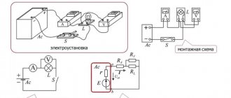
Connection diagram of compensating installations
In three-phase networks, compensating capacitors are placed in threes according to two well-known schemes:
- Star.
- Triangle.
Reactive power in these cases is calculated using the formulas presented in the figure. The Greek omega denotes the circular frequency of the network (2 x Pi x 50 Hz). From the relationships it turns out that the capacitor connection circuit in a triangle is more profitable: the power has increased by 3 times. Explanation - the star uses phase voltage, 1.73 times less than linear. The compensated reactive power depends on the square of this parameter.
For these reasons, three-phase capacitors are always made in a triangle, and for a star, you need to ask for an individual order (three single-phase capacitors). There is a flip side to the coin: the voltage is 1.05; 3.15; 6.3; 10.5 kV all capacitors are single-phase. It is permissible to connect as you please. A star, for example, has a lower operating voltage, which means that each capacitor individually will be cheaper. Both circuits cannot be classified as parallel connections; similar triplets, however, are combined into:
- groups;
- sections;
- installations.
And within associations, single-phase capacitors can be connected in series and in parallel, and three-phase capacitors can be connected exclusively in parallel. It is recommended to select the same values for all individual elements. This simplifies the calculation and equalizes the load across parts of the electrical circuit. There are known installations where there is a mixed connection for each phase. Parallel branches of series connection of capacitors are formed.
Installations are made single-phase or three-phase. In networks with a voltage of 380 V, parallel connection of capacitors is always used. An exception is the case of using equipment with one phase of 220 V (phase) and 380 V (linear). Then an individual installation (or group) is installed under the device, compensating reactive power. In lighting networks, capacitors are mostly placed after the switch for obvious reasons. In other cases - depending on the characteristics of the object’s functioning.
For voltages of 3, 6 and 10 kV, single-phase capacitors are connected with a regular or double star (see figure). One terminal is grounded (solidly grounded neutral). For this reason, the use of single-phase capacitors is allowed, including those with a single insulated terminal. In the latter case, you need to make sure that the neutral conductor goes to the product body.
The main switch is placed in a certain section of the protected equipment (geographically) and controls the compensation circuit in general, activates or removes additional reactance. If process equipment is idle in a particular sector, the main switch will break the compensation circuit. Capacitor units are usually located together in a dedicated room, electrically connected in parallel. In front of each there is a relay control circuit switch to increase or decrease the total capacity of the compensators.
Depending on the equipment used by the enterprise, the amount of reactive power determines the assistance of capacitor units, which are flexibly adjusted to existing needs. Eventually:
- Equipment sections are connected in parallel. This is easy to understand if you imagine household appliances powered by a single extension cord. All are connected in parallel. But they are installed, for example, in different workshops, sectors, etc. There are cases when one large power plant (for example, a hydroelectric power station generator) is divided into relatively independent sections.
- Capacitor units are connected in parallel, but, as a rule, in one place, so that it is possible to automatically or manually easily adjust the total capacity by switching lightweight switches. One capacitor can work to compensate the reactive power of any of the sections or both at once.
Legend
With the abbreviated system, letters and numbers are applied, where a letter indicates a subclass, a number indicates a group, depending on the dielectric used. The third element indicates the registration number of the product type.
With a full symbol, the parameters and characteristics are indicated in the following sequence:
- symbol of the design of the product;
- rated voltage of the product;
- nominal capacity of the product;
- permissible deviation of capacitance;
- temperature stability of the product container;
- rated reactive power of the product.
Series-parallel (mixed) connection of capacitors
A series-parallel connection of capacitors is a circuit that includes sections with both parallel and series connections of capacitors.
Figure 4 shows an example of a circuit section with a mixed connection of capacitors.
Figure 4. Series-parallel connection of capacitors.
When calculating the total capacitance of such a section of a circuit with a series-parallel connection of capacitors, this section is divided into the simplest sections, consisting only of groups with series or parallel connection of capacitors. Next, the calculation algorithm looks like:
1. Determine the equivalent capacitance of sections with series connection of capacitors.
2. If these sections contain series-connected capacitors, then first calculate their capacitance.
3. After calculating the equivalent capacitances of the capacitors, redraw the circuit. Typically, a circuit of equivalent capacitors connected in series is obtained.
4. Calculate the capacity of the resulting circuit.
One example of calculating capacitance for a mixed connection of capacitors is shown in Figure 5.
Figure 5. An example of calculating a series-parallel connection of capacitors.
More information about calculating the connection of capacitors can be found in the multimedia textbook on the basics of electrical engineering and electronics:
Footnotes
1 The author would like to thank Chris Burkett, Application Engineer at TDK, for his explanation of “what the heck is going on here.”
Murata is a registered trademark of Murata Manufacturing Co., Ltd.
TDK is a registered service mark and a registered trademark of TDK Corporation.
PS At the request of workers - a comparative photo of capacitors of various sizes. Grid pitch 5mm.
Parallel connection of capacitors
With a parallel connection circuit, their total value will be the sum of the capacitances of the individual elements. With this connection scheme, all element plates are connected in groups. One of the terminals of each element is connected to one group, and the other terminal to another group.
In this case, the voltage on all plates will be the same, because all groups are connected to the same power source. In fact, one capacitance is obtained, the total value of all capacitances in a given circuit.
To obtain a larger capacitance, a parallel connection of the capacitor is used.
For example, it is necessary to connect a three-phase motor to a single-phase 220 V network. For the operating mode of the motor, a capacitance of 135 μF is required. It is very difficult to find, but can be obtained by using a parallel connection of elements of 5, 30 and 100 μF. As a result of addition, we obtain the required unit of 135 μF.
High voltage capacitor
If a high voltage capacitor is needed, two or more low voltage capacitors can be used. It is best to combine capacitors with the most similar characteristics. Since when connected in series, capacitors are charged and discharged by the same current, then due to differences in capacitance values, capacitors can be charged to different voltage values and the greater the difference in capacitances, the greater the voltage imbalance. Another problem with such a connection is created by the spread of leakage currents. The greater the leakage current of the capacitor, the faster it will discharge, while on a capacitor with a lower leakage current the voltage will increase and over time, on the first capacitor the voltage will become zero, and on the second to full voltage. It turns out that only one capacitor is working. To balance the voltage across the capacitors, you need to connect a resistor in parallel to each capacitor in the chain. The resistance of the resistor is calculated so that the current flowing through the resistor is 10 times greater than the difference between the leakage currents of series-connected capacitors.
Series connection of capacitors.
As in the case of resistors, first of all we will consider the series connection of capacitors.
With this connection, the charges of all capacitors will be equal:
q_1 = q_2 = q_3 = q
Let us recall the formula for voltage from the previous article and determine the values:
U_1 = \frac{q}{C_1} U_2 = \frac{q}{C_2} U_3 = \frac{q}{C_3}
And the total voltage in a series connection is equal to the sum of the voltages on the circuit elements individually:
U_0 = U_1 + U_2 + U_3
But at the same time, the total voltage can be expressed through the total capacitance of the circuit:
U_0 = \frac{q}{C_0}
We equate these expressions and as a result we obtain a formula for determining the capacitance when connecting capacitors in series:
\frac{1}{C_0} = \frac{1}{C_1} + \frac{1}{C_2} + \frac{1}{C_3}
Agree, this formula resembles the expression for determining the total resistance when connecting resistors in parallel (link)
Well, we've sorted that out, let's move on.
Electrical capacity
When connecting devices for charge condensation, as a rule, the technician is interested in the electrical capacitance that will result.
Electrical capacity shows the ability of a two-terminal network to accumulate charge and is measured in farads. It may seem that the higher this value, the better, but in practice it is not possible to create all possible containers in the world, moreover, this is often not necessary, since all devices used every day use standard condensation devices .
You can connect several devices for condensation in a circuit, creating one condensing container, and the value of the characteristic value will depend on the type of connection, and there are long-known formulas for its calculation.
There is no capacitor of the required value: what to do
Very often, novice home craftsmen, having discovered a breakdown of the device, try to independently discover the cause. Having seen a burnt part, they try to find a similar one, and if this fails, they take the device for repair. In fact, it is not necessary that the indicators coincide. You can use smaller capacitors by connecting them in a circuit. The main thing is to do it right. In this case, 3 goals are achieved at once - the breakdown is eliminated, experience is gained, and family budget funds are saved.
Let's try to figure out what connection methods exist and what tasks the series and parallel connection of capacitors are designed for.
Comparison of different options
| Capacity | Voltage | |
| Parallel | Increases | Doesn't change |
| Sequential | Decreases | Increases |
| Mixed | Changes | Increases |
To select a connection, you can use the following table. On the left is the type of connection of devices, on top is the properties of the device for charge condensation.
If you need to increase the capacity, then you need to use a parallel connection, and if you increase the voltage, then a serial connection. If both are required, then it will be necessary to calculate the mixed connection of capacitors in the circuit.
Series-parallel (mixed) connection of capacitors
A series-parallel connection of capacitors is a circuit that includes sections with both parallel and series connections of capacitors.
Figure 4 shows an example of a circuit section with a mixed connection of capacitors.
Figure 4. Series-parallel connection of capacitors.
When calculating the total capacitance of such a section of a circuit with a series-parallel connection of capacitors, this section is divided into the simplest sections, consisting only of groups with series or parallel connection of capacitors. Next, the calculation algorithm looks like:
1. Determine the equivalent capacitance of sections with series connection of capacitors.
2. If these sections contain series-connected capacitors, then first calculate their capacitance.
3. After calculating the equivalent capacitances of the capacitors, redraw the circuit. Typically, a circuit of equivalent capacitors connected in series is obtained.
4. Calculate the capacity of the resulting circuit.
One example of calculating capacitance for a mixed connection of capacitors is shown in Figure 5.
Figure 5. An example of calculating a series-parallel connection of capacitors.
More information about calculating the connection of capacitors can be found in the multimedia textbook on the basics of electrical engineering and electronics:
Why is all this needed?
It may be quite fair to ask why it is necessary to connect capacitors in series if the total capacitance is less? Most likely, the first thing that comes to mind is to get a new equivalent capacitor with a lower capacitance. But in the production of microcircuits it is unlikely that they will do this, since, firstly, it is usually necessary to save space on the printed circuit board, and secondly, there is no point in spending money on two components or more if you can buy one with the required capacity.
But if there is still at least some logic in the parallel or series connection of capacitors, then who needs a mixed one at all?
The fact is that any body in nature, even human, has capacity, that is, the ability to accumulate electrical charge. If we are talking about an electrical circuit, then all its elements in practice have capacitance, and they can be thought of as capacitors. Often such capacitance is also called parasitic, because it creates various kinds of interference.
For example, we have some kind of electronic circuit with many different components that receives a signal, processes it in a certain way and outputs the result. It is known that the signal delay time mainly depends on the parasitic capacitance of the electronic components of the circuit. Because the parasitic capacitance must charge time before it begins to transmit a signal. If we want to know the delay time, we need to calculate the total capacitance of all components, converting them into a network of capacitors.
Mixed connection of capacitors
A mixed connection (series-parallel) of capacitors is used when it is necessary to increase the capacity and operating voltage of the capacitor bank.
Let's look at the mixed connection of capacitors using the examples below.
Capacitor Energy
where Q
- charge of the capacitor or capacitors to which voltage
U ;
C is the electrical capacitance of a capacitor or battery of connected capacitors to which voltage
U .
Thus, capacitors serve to accumulate and store the electric field and its energy.
15. Define the concepts of three-ray star and triangle of resistance.
Write down the formulas for converting a three-ray star of resistance into a triangle of resistance and vice versa.
Convert the circuit to two nodes (Figure 5) Figure 5 - Electrical circuit
6.EXCHANGE DIAGRAMS
To facilitate the calculation, an equivalent circuit of the electrical circuit is drawn up, i.e., a circuit that displays the properties of the circuit under certain conditions.
The equivalent circuit shows all the elements whose influence on the calculation result cannot be neglected, and also indicates the electrical connections between them that are present in the circuit.
1. Replacement diagrams for electrical circuit elements
In calculation diagrams, the energy source can be represented by an EMF without internal resistance, if this resistance is small compared to the resistance of the receiver (Fig. 3.13.6).
When r = 0 internal voltage drop Uо = 0, therefore
the voltage at the source terminals at any current is equal to
EMF: U = E =
const.
In some cases, the source of electrical energy in the design diagram is replaced by another (equivalent) circuit (Fig. 3.14, a),
where instead of EMF
E,
the source is characterized by its short circuit current IK, and instead of internal resistance, internal conductivity
g = 1/ r .
The possibility of such a replacement can be proven by dividing equality (3.1) by r:
U r =
E r - I ,
where U r =
Io
is a certain current equal to the ratio of the voltage at the source terminals to the internal resistance;
E r = I K
- source short circuit current;
Introducing new notations, we obtain the equality I K =
Io + I ,
which is satisfied by the equivalent circuit in Fig.
3.14, a.
In this case, for any voltage at the terminals; source, its current remains equal to the short circuit current (Fig. 3.14.6):
I=Iк=const.
A source with a constant current that does not depend on external resistance is called a current source.
The same source of electrical energy can be replaced in the design circuit by an EMF source or a current source.
Get an electrical calculation software package
There is an opinion on the Internet that the author of Electronics Workbench is a subsidiary of National Instruments Corporation, which develops software. Not true. From the copyright window of the mentioned application you can see: the development was carried out by the Interactive Image Technologies department.
The above-mentioned division gained independence in 1995. The department focused on advertising and educational materials. Electronics Workbench is designed for educational purposes for Canadian students. Then the software product spread worldwide, for some time now it has been called Multisim.
The updated software product is sold by official dealers; the list is presented on the official website of the National Instruments company: russia.ni.com/contact. At the time of the study, the lucky ones who received the right to buy software without leaving the city were residents of Moscow and St. Petersburg. Good luck to those who decide to contact official representatives, new features have been added to Multisim:
- More than 36,000 circuit elements.
- Possibility of developing printed circuit boards based on the assembled electrical circuit.
- Advanced analysis options instead of the wretchedness shown in screenshots of the 20-year-old version.
Why electrolytic capacitors fail and what to do
Often, to repair faulty electronic equipment, it is enough to find and replace swollen capacitors. The fact is that their lifespan is short - 1000-2000 thousand working hours. Then it usually fails and needs to be replaced. And this is at normal voltage not higher than the rated voltage. This happens because the dielectric in capacitors is most often liquid. The liquid gradually evaporates, the parameters change and, sooner or later, the capacitor swells.
Electrolytic capacitors have special notches on the top of the case to avoid explosion if they fail.
The electrolyte dries out not only during operation. Even just “from time to time.” This is a design feature of electrolytic capacitors. Therefore, you should not install capacitors soldered from old circuits or those that have been stored in the workshop for several years (or decades). It's better to buy "fresh", but check the production date.
Is it possible to extend the life of capacitors? Can. We need to improve heat dissipation. The less the electrolyte heats up, the slower it dries. Therefore, you should not install the equipment near heating appliances.
Radiators are installed to improve heat dissipation
Secondly, you need to make sure that the coolers work well. Third, if there are parts nearby that actively heat up during operation, the capacitors must somehow be protected from the temperature.
How to choose a replacement
If you often have to change the same capacitor, it is better to replace it with a more “powerful” one - the same capacity, but with a higher voltage. For example, instead of a 25 volt capacitor, put a 35 volt capacitor. Just keep in mind that more powerful capacitors are larger. Not every board allows such a replacement.
A capacitor of the same capacity, but designed for a higher voltage, has a larger size
You can place several capacitors in parallel with the same voltage, selecting the ratings so as to obtain the required capacity. What will it give? Better tolerance of current ripples, less heating and, as a result, longer service life.
What happens if you install a capacitor with a larger capacity?
Often the idea comes to mind to replace a burnt or swollen capacitor with a larger capacity. After all, it should heat up less. So, in any case, it seems. Capacity has practically nothing to do with the degree of heating of the case. And there will be no gain in this.
Electrolytic capacitor device
According to regulatory documents, the deviation of the capacitor rating is allowed within 20%. You can safely bet over/under on this number. But this may lead to changes in the operation of the device. So it’s better to find a “native” denomination. And keep in mind that it is not always possible to install a large container. It is possible if the capacitor is at the input and smoothes out power surges. This is where a large container is appropriate if there is enough space to install it. This definitely cannot be done where the capacitor acts as a filter that cuts off given frequencies.
You can change it to the same capacity, but a slightly higher voltage. It makes sense. But the dimensions of such a capacitor will be much larger. Not every board can install it. And keep in mind that its body should not come into contact with other parts.
about the author
Mark Fortunato
has spent most of his life trying to get those pesky electrons to be in the right place at the right time. He's worked on everything from speech recognition systems to microwaves to LED lights (the ones that adjust properly, mind you!). He has spent the last 16 years helping clients tame their analog circuits. Mr. Fortunato is now the lead specialist for Maxim Integrated's Communications and Automotive Solutions division. When he's not herding electrons, Mark enjoys coaching youth, reading journalism, and watching his youngest son play lacrosse and his oldest son play music. Overall, he strives to live in harmony. Mark is very sorry that he will no longer meet Jim Williams or Bob Pease.
Mixed method
Combines parallel and serial connections.
At the same time, sections with a serial connection are characterized by the properties of a serial connection, and sections with a parallel connection are characterized by the properties of a parallel connection.
It is used when neither the electrical capacity nor the voltage rating of commercially available appliances is suitable for the task. This problem usually occurs in radio engineering.
To determine the total value of electrical capacitance, you will first need to determine the same value for parallel-connected two-terminal networks, and then for their series connection.
Mixed connection
But, it is worth considering that to connect different capacitors, it is necessary to take into account the network voltage. For each semiconductor, this indicator will differ depending on the capacitance of the element. It follows that individual groups of small-capacity semiconductor biterminals will become larger when charging, and vice versa, a large-sized electrical capacitance will require less charging.
Scheme: mixed connection of capacitors
There is also a mixed connection of two or more capacitors. Here, electrical energy is distributed simultaneously using parallel and series connections of electrolytic cells in a circuit. This circuit has several sections with different connections of condensing two-terminal networks. In other words, on one the circuit is connected in parallel, on the other - in series. This electrical circuit has a number of advantages compared to traditional ones:
- Can be used for any purpose: connecting an electric motor, machine equipment, radio equipment;
- Simple calculation. For installation, the entire circuit is divided into separate sections of the circuit, which are calculated separately;
- The properties of the components do not change regardless of changes in the electromagnetic field or current strength. This is very important when working with opposite two-terminal networks. The capacitance is constant at a constant voltage, but the potential is proportional to the charge;
- If you need to assemble several non-polar semiconductor two-terminal networks from polar ones, then you need to take several single-pole two-terminal networks and connect them in a back-to-back (triangle) manner. Minus to minus, and plus to plus. Thus, by increasing the capacitance, the operating principle of a bipolar semiconductor changes.
How to calculate the energy of a charged capacitor: we derive the final formula
The first thing you need to do for this is to calculate the force with which the plates are attracted to each other. This can be done using the formula F = q₀ × E, where q₀ is an indicator of the magnitude of the charge, and E is the tension of the plates. Next, we need an indicator of the tension of the plates, which can be calculated using the formula E = q / (2ε₀S), where q is the charge, ε₀ is a constant value, S is the area of the plates. In this case, we obtain a general formula for calculating the force of attraction between two plates: F = q₂ / (2ε₀S).
The result of our conclusions will be the conclusion of the expression for the energy of a charged capacitor, as W = A = Fd. However, this is not the final formula we need. We follow further: taking into account the previous information, we have: W = dq₂ / (2ε₀S). With the capacitance of the capacitor expressed as C = d / (ε₀S), we obtain the result W = q₂ / (2C). Applying the formula q = CU, we get the result: W = CU² /2.
The editors of Seti.guru advise you to save this memo
Of course, for a novice radio amateur, all these calculations may seem complex and incomprehensible, but with desire and some perseverance, you can figure them out. Having delved into the meaning, he will be amazed at how simply all these calculations are made.
Why do you need to know the energy indicator of a capacitor?
In fact, energy calculations are rarely used, but there are areas in which it is necessary to know this
For example, a camera flash - here calculating the energy indicator is very important. It accumulates over a certain time (several seconds), but is issued instantly
It turns out that a capacitor is comparable to a battery - the only difference is in capacity.
No flash can work without an energy storage device, such as a capacitor.