Dependence of the current in a conductor on the voltage at its ends. Electrical resistance of the conductor
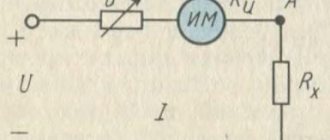
Let's conduct an experiment; to do this, we will connect a current source to a conductor (resistor), to which we will connect an ammeter in series (to measure the current on the resistor), and in parallel - a voltmeter (to measure the voltage on the resistor) (see Fig. 1). Initially, at a voltage of 1 V, the current is 1 A. When the voltage is doubled, to 2 V, the current also doubles (2 A) (see Fig. 2).
Rice. 1. Electrical circuit for the experiment
From experience it is clear that when the voltage at the ends of the conductor increases or decreases, the current strength in the conductor will increase or decrease by the same amount. This dependence was first experimentally obtained by the German scientist Georg Ohm in 1826. From the mathematics course we know that it can be written in this form:
,
where I – current strength; U – voltage; k – proportionality coefficient.
Let's present the dependence in the form of a graph (see Fig. 3). Such a graph of the dependence of the current in a conductor on the voltage at its ends is called the current-voltage characteristic (can also be presented in the form of a table).
Rice. 2. Ammeter readings when voltage changes
Rice. 3. Current-voltage characteristics of the conductor
For the next experiment, we will assemble an electrical circuit similar to the previous one, replacing the conductor in it (see Fig. 4). Initially, at a voltage of about 1.5 V, the current is approximately 0.3 A. When the voltage is increased to 3 V, the current will increase to approximately 0.6 A (see Fig. 5).
| Rice. 4. Electrical circuit for the experiment | Rice. 5. Ammeter readings when voltage changes |
After conducting experiments with various conductors, it was established that the current strength in a conductor is always proportional to the voltage at its ends, while the proportionality coefficient depends on the conductor. Thus, the current strength in a conductor depends not only on the voltage at its ends, but also on the properties of the conductor. That is, the dependence can be written like this:
or ,
where R is the electrical resistance of the conductor.
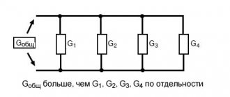
Quantity – conductivity. The unit of conductivity is called the Siemens (Sm), named after the German physicist Ernest Siemens. 1 cm is the electrical conductivity of a conductor with a resistance of 1 ohm.
With the same voltage at the ends of the conductors, the current strength is less in the conductor that has higher resistance. That is, the greater the resistance of the conductor, the stronger the conductor opposes the passage of current. In this case, part of the electrical energy is converted into the internal energy of the conductor.
Electrical resistance is a physical quantity that characterizes the property of a conductor to resist electric current. The SI unit of resistance is Ohm.
1 Ohm is the resistance of a conductor in which, at a voltage at the ends of 1 V, the current strength is 1 A.
Ohm's law for a circuit section
Everything that is known about the resistance of conductors, as well as the dependence of current on voltage at the ends of the conductor, is also true for a section of a circuit with any number of conductors. That is, we can formulate Ohm's law for a section of the circuit :
The current strength in the circuit is directly proportional to the voltage at the ends of this section and inversely proportional to the electrical resistance of this section of the circuit:
,
where R is the resistance of the circuit section, which depends only on the properties of the conductors that make up the section.
Ohm's law is one of the most important physical laws; most of the calculations of electrical circuits in electrical engineering are based on this law.
The history of the discovery of Ohm's law for a section of a circuit
Let us remember that several previous lessons were devoted to the study of such physical quantities as current, voltage and resistance. We examined the nature of the occurrence of electrical resistance, its unit of measurement, and briefly indicated on what general factors it depends. We also know that the current strength depends on the electric field that arises in the conductor, and the voltage depends on the work of this field. But electric current is the ordered movement of charged particles, which is also characterized by the work of electric current. Therefore, there must be some connection between all these concepts: current, voltage, resistance.
This dependence was first determined in 1826 by the German physicist Georg Ohm (1789–1854) (Fig. 1). He conducted a very large number of experiments in which, first of all, he studied the dependence of the current in the circuit on voltage. His experiments were carried out as follows: without changing anything in the electrical circuit, he connected a different, larger number of current sources to it, as a result of which the voltage supplied to the circuit increased, which led to an increase in current strength. Such numerous experiments led to the derivation of the law of current strength from electrical resistance.
Rice. 1. Georg Ohm ()
Let us describe the scheme of Georg Ohm's experiments. He connected a conductor to the electrical circuit, on which, using a voltmeter and ammeter, the voltage and current were measured, respectively, the switch and the current source (Fig. 2). Let us pay attention to the fact that several current sources are connected in the circuit, and changing their number allows us to observe the change in the current strength in the circuit depending on the voltage.
Rice. 2. Scheme of experiments by G. Ohm
As a result of the measurements, the dependence can be traced, where the voltage is measured at the AB terminals, i.e., on the conductor.
In order to observe the dependence of current on resistance, in the same circuit one should now not change the number of current sources, but change the conductors, i.e., the resistance of the circuit. Georg Ohm did the following: instead of one conductor, he connected another with twice the length, i.e., with twice the resistance (you will learn why this is so in the next lesson). Similarly, he connected conductors with other lengths and obtained a relationship of the following form: . That is, as the resistance of the conductor increases, the current strength in it decreases.
On the graph, the dependence of the current in the conductor on the resistance is as follows (Fig. 3).
Rice. 3. Dependence of current strength in a conductor on resistance
This dependence is called inversely proportional. It took Ohm quite a long time to obtain this dependence, but this is what led him to the conclusion of the most important law of electrodynamics - Ohm’s law for a section of a circuit. Having put together the two dependencies that we showed above, Om came to his law.
Kinds
A conductor is a medium or object that is capable of conducting electric current. Inside it, when connected to an energy source, a charged particle begins to actively move. An ammeter shows the increase in electrical voltage in a circuit. When considering different types of conductors, the electrical conductivity and type of material are taken into account:
- copper;
- aluminum;
- metal;
- gold;
- an alloy of nickel and chromium.
You may be interested in: Features of tantalum capacitors
In the scientific community there is the concept of a superconductor, which is considered ideal. It has a significant dielectric loss angle. When current flows from a circuit, the percentage of bias is taken into account. For a superconductor, this parameter is minimal.
From copper
Copper belongs to the components of group 11 from the table of chemical elements. According to the classification, it is lamellar and is found in different types. Often the substance has a pink tint. In electrical engineering, copper has a low resistivity and shares a niche with silver and gold.
Silver and gold
The material is applicable in the manufacture of wiring and printed circuit boards. Another substance is in demand in the manufacture of electric drives. Considering complex controlled electromechanical systems, it is noticeable that they use windings with low resistivity.
If we evaluate power transformers, they also use this metal, but it is often used with impurities. This is necessary to reduce the electrical conductivity rate. In printed circuit boards, copper is used in tandem with aluminum. When considering radio components, copper-based alloys, which are also characterized by low resistance, remain in demand.
When disassembling personal computers, the substance is found in bronze or brass. Zinc or nickel additives are also used. To increase the elasticity of the conductor, other materials are used, such as tin and zinc. According to the resistivity table, the substance is assigned an indicator of 0.0157 Ohm.
Properties of copper
Made of aluminum
Among the elements of group 13 in the table, aluminum stands out. It is an excellent conductor in a circuit and is made of paramagnetic metal. The color has a silvery tint. The conductor lends itself well to mechanical processing. In addition to significant electrical conductivity, corrosion resistance is noted.
During heat treatment, an oxide film is formed that protects the surface. There are various aluminum compounds found in nature. If we consider standard wire of small cross-section, it is in demand in electric coils. The substance has low density and mass, so analogues are difficult to find. Using aluminum in moving parts can improve their performance.
The conductor is often found in hard drives and audio systems. Wires coated with a layer of varnish remain in demand. There are enameled analogues that are characterized by increased security. Rubber and beryl are used as insulation. Manufacturers produce conductors with a cross section of 0.003 mm.
Properties of aluminum
In addition to inductors, wire can be installed in inductors, loudspeakers, and headphones. Regarding connections, there are options with alunites. Additional information about physical properties:
- low melting point;
- high heat capacity;
- significant hardness;
- weak paramagnetic;
- wide temperature range.
You may be interested in this. Plus is it phase or zero
Aluminum is found in printed circuit boards because it can be stamped. Corrosion resistance is an added benefit. Aluminum conductors are popular and in demand in industry. Resistivity - 0.028 Ohm. It is also necessary to consider the disadvantage of a significant content of impurities.
Made of metal
Among metals, the following are considered common types of conductors:
- lead;
- tin;
- platinum;
- nickel;
- tungsten.
Lead is a group 14 element that can be used as a conductor. It has a maximum density of 11.35 grams per cubic meter. The scope of application is limited because the material is toxic and belongs to heavy metals. The history of the origin of the formula is unclear, there are only guesses.
Metal groups
If we talk about conductor elements, lead nitrate is often used. In power sources and backup units there is a version with chloride. Considering inorganic compounds, the material that stands out is telluride. It is suitable as a thermoelectric conductor and is therefore used in power plants of various capacities. The metal element is also in demand in refrigerators.
If we consider telluride in detail, a significant dielectric constant should be attributed to one of the features. In addition to lead, it contains tin and tellurium. Separately, the substances are found in photoresistors and diodes. If you disassemble semiconductor devices, the elements are contained in stabilizers and indicate the direction of current.
Important! Tin is a conductor from group 14 of chemical elements. The material is safe and does not contain toxic substances.
Along with gold, tin has excellent anti-corrosion properties. Disulfide is often used in technology. Tin dioxide shows the highest resistance value. In batteries it is used in its pure form. When considering galvanic cells, it is worth mentioning manganese-tin dioxide.
Platinum is a conductor from the tenth group of chemical elements. The presented metal has an electrical resistance of 0.098 Ohms and is characterized by increased density. If we consider the scope of application, the substance is often found in laser technology. We are talking about printers, as well as measuring instruments.
Properties of platinum
Additionally, platinum is used in electromagnetic relays. In the presented automatic devices it acts as a conductor. We are talking about mechanical, thermal or optical relays. In electronic sensors, platinum is contained in smaller quantities, but is used due to its wide temperature range. In particular, you can consider an electronic resistance thermometer. The resistive element is mostly made of platinum.
You may be interested in Features of Ohm's law for alternating current
From gold
The resistivity of gold is 0.023 Ohm. The material belongs to the first group of metals and is soft in physical properties. Gold can also be found in pure form with impurities. The density is 19.32 g/cm³, the scope of application is wide. In industry, the conductor is in demand as solder.
Solder gold
It can be applied to various surfaces and serves as an excellent material for joining workpieces due to its low melting point. Gold is also in demand for protection against corrosion.
Flaws:
- softness of the material;
- subject to pitting corrosion.
If you use a material with additives, the melting point decreases. This also affects the mechanical properties of the substance.
Gold with additives
Ohm's law for a circuit section
Ohm's law for a circuit section : current is directly proportional to voltage and inversely proportional to resistance:
Comment. This law underlies the science called electrical engineering.
Since the voltage in the law is considered at the ends of the conductor and the resistance of the conductor itself is taken into account, the law is applicable specifically to a section of the circuit, that is, to any part of it.
Designations:
voltage, V;
current strength, A;
resistance, Ohm.
When working with Ohm's law, you should understand that it can be fulfilled separately for each section of the circuit under consideration with different values of the parameters included in it.
In the next lesson we will talk about what parameters the conductor resistance depends on.
Parameters that determine conductor resistance
In previous lessons, we already raised the question of how electrical resistance affects the current strength in a circuit, but we did not discuss what specific factors the resistance of a conductor depends on. In today's lesson we will learn about the parameters of a conductor that determine its resistance, and we will learn how Georg Ohm investigated the resistance of conductors in his experiments.
To obtain the dependence of the current in the circuit on the resistance, Ohm had to conduct a huge number of experiments in which it was necessary to change the resistance of the conductor. In this regard, he was faced with the problem of studying the resistance of a conductor depending on its individual parameters. First of all, Georg Ohm drew attention to the dependence of the resistance of a conductor on its length, which was already discussed in passing in previous lessons. He concluded that as the length of the conductor increases, its resistance also increases in direct proportion. In addition, it was found that the resistance is also influenced by the cross-section of the conductor, i.e., the area of the figure that is obtained from a transverse section. Moreover, the larger the cross-sectional area, the lower the resistance. From this we can conclude that the thicker the wire, the lower its resistance. All these facts were obtained experimentally.
In addition to geometric parameters, the resistance of a conductor is also influenced by a quantity that describes the type of substance of which the conductor is composed. In his experiments, Om used conductors made of various materials. When using copper wires, the resistance was one way, silver - another, iron - a third, etc. The value that characterizes the type of substance in this case is called resistivity .
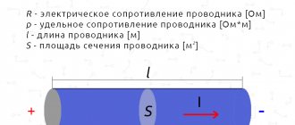
Thus, we can obtain the following dependences for the conductor resistance (Fig. 1):
- Resistance is directly proportional to the length of the conductor, which is measured in m in SI;
- Resistance is inversely proportional to the cross-sectional area of the conductor, which we will measure in mm2 due to its smallness;
- Resistance depends on the specific resistance of the substance (read “rho”), which is a tabular value and is usually measured in .
Rice. 1. Explorer
Influence of cable length and cross-section on voltage losses
Electricity losses are an inevitable cost for its transportation by wire, regardless of the length of the transmission line. They also exist on overhead power lines hundreds of kilometers long and on sections of electrical wiring several tens of meters long in the home electrical network. They occur primarily because any wires have a finite resistance to electric current. Ohm's law, which each of us had the opportunity to become familiar with in school physics lessons, states that voltage (U) is related to current (I) and resistance (R) by the following expression:
U = I R,
It follows from it that the higher the resistance of the conductor, the greater the voltage drop (loss) on it at constant current values. This voltage leads to heating of the conductors, which can lead to melting of the insulation, short circuit and fire of the electrical wiring.
When transmitting electricity over long distances, losses can be avoided by reducing the strength of the transmitted current; this is achieved by repeatedly increasing the voltage to hundreds of kilovolts. In the case of low-voltage networks with a voltage of 220 (380) V, losses can be minimized only by choosing the correct cable cross-section.
Why does the voltage drop and how does it depend on the length and cross-section of the conductors
To begin with, let's look at a simple everyday example of the private sector within a city or large village, in the center of which there is a transformer substation. Residents of houses located in close proximity to it complain about the constant replacement of quickly burning out light bulbs, which is quite natural, because the voltage in their network reaches 250 V and higher. While on the outskirts of the village, at maximum load on the network, it can drop to 150 volts. In this case, one conclusion suggests itself: the voltage drop depends on the length of the conductors represented by linear wires.
Let us specify what the value of the conductor resistance depends on using the example of copper wires, which are preferred today. To do this, let’s go back to the school physics course, from which we know that the resistance of a conductor depends on three quantities:
- material resistivity – ρ;
- conductor segment length – l;
- cross-sectional area (provided that it is the same along the entire length) – S.
All four parameters are connected by the following relationship:
R = ρ l/S,
It is obvious that the resistance increases as the length of the conductor increases and falls as the cross-section of the conductor increases.
For copper conductors, the resistivity is 0.0175 Ohm mm²/m, which means that a kilometer of copper wire with a cross section of 1 mm² will have a resistance of 17.5 Ohms, in a real situation it may differ, for example, due to the purity of the metal (the presence of impurities in the alloy).
For aluminum conductors, the resistance value is even higher, since the resistivity of aluminum conductors is 0.028 Ohm mm²/m.
Now let's return to our example. Let the distance from the substation to the outermost house be 1 km and the 220 volt power supply to it is laid with grade A aluminum wire, with a minimum cross-section of 10 mm². The distance that the electric current needs to travel is the sum of the length of the neutral and phase wires, that is, in our example it is necessary to apply a coefficient of 2, so the maximum length will be 2000 m. Substituting our values in the last formula, we obtain a resistance value equal to 5.6 Ohms.
Whether this is a lot or a little is clear from Ohm’s law mentioned above, so for a consumer with a rated current of only 10 amperes, in the example given, the voltage drop will be 56 V, which will be spent on heating the street.
Of course, if it is impossible to reduce the distance, you should choose a larger cross-section of wires, this also applies to internal wiring, but this leads to an increase in costs for cable and wire products. The optimal solution would be to correctly calculate the wire cross-sections, taking into account the maximum permissible load.
Still have questions?
Fill out the feedback form below, our specialists will contact you, advise you, and tell you about possible ways to solve your problem.
order a consultation
Resistivity
As an example, here is a table of the resistivity values of some metals, which were obtained experimentally:
Resistivity ,
| Copper | 0,0175 |
| Silver | 0,016 |
| Iron | 0,098 |
| Aluminum | 0,027 |
It is worth noting that among the good conductors, which are metals, precious metals are the best, while silver is considered the best conductor, since it has the smallest low resistivity. This explains the use of precious metals when soldering particularly important elements in electrical engineering. From the values of the resistivity of substances, one can draw conclusions about their practical application - substances with a high resistivity are suitable for the manufacture of insulating materials, and those with a small resistivity are suitable for conductors.
Comment. In many tables, resistivity is measured in , which is related to the SI measurement of area in m2.
The physical meaning of resistivity is the resistance of a conductor with a length of 1 m and a cross-sectional area of 1 mm2.
Dependence of electrical resistance on the cross-section, length and material of the conductor
The resistance of various conductors depends on the material from which they are made.
You can check this practically using the following experiment.
Figure 1. Experience showing the dependence of electrical resistance on conductor material
Let's select two or three conductors from different materials, possibly smaller, but with the same cross-section, for example, one is copper, another is steel, the third is nickel. a and b to the bar at a distance of 1-1.5 m from one another (Fig. 1) and connect the battery to them via an ammeter. Now, alternately between clamps a and b , we will turn on first the copper, then the steel and, finally, the nickel conductor for 1-2 seconds, observing in each case the deflection of the ammeter needle. It will not be difficult to notice that the largest current will flow through the copper conductor, and the smallest - through the nickel conductor.
It follows from this that the resistance of a copper conductor is less than that of a steel conductor, and the resistance of a steel conductor is less than that of a nickel conductor.
Thus, the electrical resistance of a conductor depends on the material from which it is made.
To characterize the electrical resistance of various materials, the concept of so-called resistivity has been introduced.
Definition: Specific resistance is the resistance of a conductor with a length of 1 m and a cross-section of 1 mm2 at a temperature of +20 C°.
Resistivity is denoted by the letter ρ (“rho”) in the Greek alphabet.
Each material from which a conductor is made has a certain resistivity. For example, the resistivity of copper is 0.0175 Ohm*mm2/m, i.e. a copper conductor 1 m long and 1 mm2 cross-section has a resistance of 0.0175 Ohm.
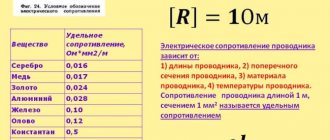
Below is a table of resistivities of materials most commonly used in electrical engineering.
Resistivity of materials most commonly used in electrical engineering
| Material | Specific resistance, Ohm*mm2/m |
| Silver | 0,016 |
| Copper | 0,0175 |
| Aluminum | 0,0295 |
| Iron | 0,09-0,11 |
| Steel | 0,125-0,146 |
| Lead | 0,218-0,222 |
| Constantan | 0,4-0,51 |
| Manganin | 0,4-0,52 |
| Nikelin | 0,43 |
| Tungsten | 0,503 |
| Nichrome | 1,02-1,12 |
| Fechral | 1,2 |
| Coal | 10-60 |
It is interesting to note that, for example, a nichrome wire 1 m long has approximately the same resistance as a copper wire about 63 m long (with the same cross-section).
Let us now examine how the dimensions of the conductor , i.e. length and cross-section, influence the value of its resistance.
For this we will use the diagram shown in Fig. a nickel wire between clamps a and b Having noticed the ammeter reading, we disconnect the conductor from terminal b , which connects the device to the battery negative, and with the free end of the conductor we touch the nickel wire at some distance from terminal a (Fig. 2). Having thus reduced the length of the conductor connected to the circuit, it is easy to notice from the ammeter reading that the current in the circuit has increased.
Figure 2. Experiment showing the dependence of electrical resistance on the length of the conductor
This suggests that as the length of the conductor decreases, its resistance decreases. If you move the end of the conductor along the nickel wire to the right, i.e., to terminal b , then, observing the ammeter readings, we can conclude that as the length of the conductor increases, its resistance increases .
Thus, the resistance of a conductor is directly proportional to its length, i.e. the longer the conductor, the greater its electrical resistance.
Let us now find out how the resistance of a conductor depends on its cross-section, i.e., on its thickness.
For this purpose, we will select two or three conductors from the same material (copper, iron or nickel), but of different cross sections and connect them alternately between terminals a and b , as shown in Fig. 1.
By observing the ammeter readings each time, you can make sure that the thinner the conductor, the less current in the circuit, and therefore, the greater the resistance of the conductor. And, conversely, the thicker the conductor, the greater the current in the circuit, and therefore, the lower the resistance of the conductor.
This means that the resistance of a conductor is inversely proportional to its cross-sectional area, i.e. the thicker the conductor, the lower its resistance, and, conversely, the thinner the conductor, the greater its resistance.
To better understand this relationship, imagine two pairs of communicating vessels (Fig. 3), with one pair of vessels having a thin connecting tube, and the other having a thick one.
Figure 3. Water will move faster through a thick tube than through a thin one.
It is clear that when one of the vessels (each pair) is filled with water, its transfer to the other vessel through a thick tube will occur much faster than through a thin tube. This means that a thick tube will have less resistance to water flow. In the same way, it is easier for electric current to pass through a thick conductor than through a thin one, i.e., the first offers it less resistance than the second.
Summarizing the results of our experiments, we can draw the following general conclusion:
The electrical resistance of a conductor is equal to the resistivity of the material from which the conductor is made, multiplied by the length of the conductor and divided by its cross-sectional area.
Mathematically, this dependence is expressed by the following formula:
where R is the conductor resistance in Ohm;
ρ—material resistivity in Ohm*mm2/m;
l is the length of the conductor in m;
S—cross-sectional area of the conductor in mm2.
Note. The cross-sectional area of a round conductor is calculated by the formula
where π is a constant value equal to 3.14;
d—conductor diameter.
The above dependence makes it possible to determine the length of the conductor or its cross-section if one of these quantities and the resistance of the conductor are known.
So, for example, the length of the conductor is determined by the formula:
If it is necessary to determine the cross-sectional area of the conductor, then the formula takes the following form:
Having solved this equality with respect to ρ, we obtain an expression for determining the resistivity of the conductor:
The last formula must be used in cases where the resistance and dimensions of the conductor are known, but its material is unknown and, moreover, difficult to determine by appearance. By determining the resistivity of a conductor using the formula, you can find a material that has such a resistivity.
DID YOU LIKE THE ARTICLE? SHARE WITH YOUR FRIENDS ON SOCIAL NETWORKS!
Related materials:
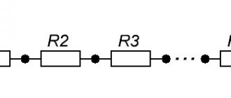
- Resistors. Types of resistors
- Types of resistors
- Designation of resistors on diagrams
- Connection of resistors
- Dependence of conductor resistance on temperature
Add a comment
Conductor resistance formula
The formula for calculating the electrical resistance of a conductor, based on the above considerations, is as follows:
If you pay attention to this formula, you can conclude that it expresses the resistivity of the conductor, i.e., by determining the current and voltage on the conductor and measuring its length with cross-sectional area, you can use Ohm’s law and the specified formula to calculate resistivity. Then, its value can be compared with the data in the table and determine what substance the conductor is made of.
All parameters that affect the resistance of conductors must be taken into account when designing complex electrical circuits, such as power lines, for example. In such projects, it is important to balance the ratios of lengths, cross-sections and materials of conductors to effectively compensate for the thermal effect of current.
The next lesson will look at the design and operating principle of a device called a rheostat, the main characteristic of which is resistance.
Take the test
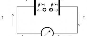
Electric current and resistance
In the case when a constant external power source is connected, creating an electric field, an orderly movement of free electrons begins to occur from end to end inside the conductor. If there were no obstacles, then such a conductor would have zero resistance and superconductivity. In some cases, in conditions of ultra-low temperatures, it is possible to achieve a similar result.
Under normal conditions, at normal temperatures, certain obstacles arise in conductors that impede the free passage of electrons. Because of this, a situation arises called electrical resistance of the conductor.