In this instruction, as an example, we will consider getting started in the Windows operating system. For Microsoft operating systems (Windows 2000/Vista), the differences are minor, they mainly relate to the names of the tabs in the Device Manager. In other operating environments, such as Linux, FreeBSD, Mac OS X, etc., the setup procedure is significantly different. If you need to organize work with this software, we recommend looking for answers to questions on the developer’s main website //www.arduino.cc.
Let's take Arduino Uno as the connected platform. The difference with other boards is minimal.
Cable for communication with PC
To transfer data from a personal computer to Arduino, you need to find the appropriate cable. The cable is not supplied with individual boards; it is only included in the Arduino starter kit for practicing designer-programmers.
Arduino U no , Arduino M ega 2560 are connected by a cable with USB type A plugs. This cable is often used to connect a printer or scanner.
Arduino Leonardo , Arduino Due have a micro USB type B socket for connection.
Arduino Nano, Freeduino Nano are connected via a mini USB type B socket.
To connect Freeduino MaxSerial you will need a 9M-9F serial cable.
Installing Arduino IDE
Arduino IDE is an integrated software development environment for Arduino devices, installed on a computer.
Depending on the board model, it is important to choose the right version of Arduino IDE:
- Arduino IDE 1.6.4 - for many boards except Arduino Leonardo ETH and Arduino M0 (software from Arduino LLC).
- Arduino IDE 1.7.7 - for all types of boards (software from Arduino SRL).
Partial software incompatibility was the result of disagreements between the founding fathers of Arduino, Italians Massimo Banzi and Gianluca Martino, who could not agree on the further course of development of the company. The plant, which develops and produces original Arduino platforms, under the management of Gianluca Martino, split from the parent company Arduino LLC and became an independent company Arduino SRL (formerly Smart Projects Srl).
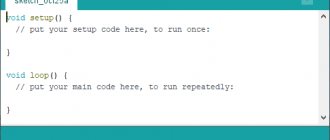
Launching Arduino IDE
After launching the successfully installed Arduino IDE, the graphical console should open, as in the picture below.
There is a problem : Arduino IDE does not start.
Remedy.
Most likely, the computer has an inappropriate JRE (Java Runtime Environment) installed on it, which is required to run graphical applications.
Return to reinstalling the Arduino IDE: this time the installer will begin the job of setting up the JRE.
Connecting Arduino boards to a computer
After successfully running the Arduino IDE, it's time to link some Arduino platform to your computer. As you already know, connecting Arduino boards to a PC is done via a USB cable.
By connecting the Arduino console to the PC, one LED “ON” will light up and the other “L” will start blinking. This means that power is supplied through the cable and the microcontroller has begun to execute the factory-preset Blink program.
All that remains is to find out what COM port number the computer assigned to our Arduino board , which is important for the correct operation of the Arduino IDE software with the new device.
The COM port number can be found in the “Device Manager”, “Ports (COM and LPT)” tab.
On Windows systems, most likely our Arduino Uno with a serial interface will be assigned one of the COM1 or COM2 ports. For an Arduino with a USB controller, the input port will be COM4, COM5, COM6 or higher.
On Linux systems, the serial port will be USB0 or USB1.
A new Arduino device was displayed in the “Device Manager” - this means that the operating system recognized our board, found a suitable USB driver for it and assigned a number to its interface. When connecting another Arduino board together, it will be assigned a different port number.
There is a problem: when you connect the Arduino board to your computer, it does not appear in Device Manager.
Remedy:
- The USB cable or port is not inserted all the way in or is damaged.
- There is no driver for this Arduino board. If you have a Chinese Arduino or from another unknown manufacturer, try reinstalling the USB driver manually.
- Blocked by the antivirus program.
- The Arduino board is faulty.
Arduino IDE setup
In the open Arduino IDE, go to: Tools > Port > select the COM port number - tell the program the port number to which the Arduino microprocessor platform is connected.
So that the Arduino IDE firmware program does not have any doubts about what it has to work with, we indicate the type of our connected board. To do this, go to the menu: Tools > Board > select the type of your Arduino board.
There is a problem: there are no COM ports in the Port tab.
Remedy.
Obviously, the connection between the Arduino device and the computer is broken. Restore a stable connection to your PC.
Or there is no driver. You can download it at the end of the article.
How to check the connection of an Arduino device
All numerical data received through the COM port is output to the Port Monitor in the same convenient graphical environment Arduino IDE. Therefore, by clicking the corresponding “Port Monitor” icon in the upper right corner of the console or finding the corresponding item in the Tools menu, you can see by the changing numbers in the window that opens that data is being transmitted via the USB cable, which means that the Arduino board is securely connected.
Please note that at the bottom of the Port Monitor window information about the speed of operation with the COM port “19200 baud” (19200 bps) is displayed. This speed is set by default in the preinstalled sketch on the Arduino board. This sketch contains the line Serial.begin(19200), in which you can set any required baud rate, but this is only possible when working via a USB cable. If data transfer occurs via a Bluetooth radio channel, then the exchange rate with the COM port must be set in advance, exactly the same as what we select when debugging the Bluetooth module.
There is a problem: the Arduino IDE is incredibly slow when navigating through the menu.
Remedy.
In Device Manager, in the Bluetooth Serial tab, turn off the Bluetooth connection to your mobile phone. All external connections via Bluetooth significantly consume virtual memory.
Uploading the first sketch
The connection is established, the development environment is configured - now you have in your hands a well-functioning tool for flashing any AVR series microcontrollers: ATtiny, ATmega, AT90S, AT90CAN, AT90PWM.
The Arduino IDE development environment has many ready-made samples for various tasks, but to check the board’s responsiveness to flashing it is enough to make small changes to the pre-installed Blink program (blinking the “L” LED on the board).
It is enough to make your changes in the delay(1000) line in the open Blink sketch, click “Load” and detect changes in the operation of the Arduino board.
By setting delay(500) the “L” LED will blink twice as often, with a delay of half a second.
By setting delay(100) the “L” LED will light up and go out 10 times faster than the factory setting, that is, every 100 milliseconds.
There was a problem : when loading the sketch, an error like “not in sync” appeared.
Installing drivers
When installing Arduio >
FOR WINDOWS USERS
If for some reason you have not installed the Arduino drivers, you can install them manually from the program/drivers folder (screenshot No. 1). The CH341 driver for Windows can be downloaded from the link on my website, or you can search it on Google yourself. The downloaded archive must be unpacked using standard Windows tools and the installer launched (screenshot No. 2).
Next, connect the Arduino to the computer, wait until Windows recognizes and remembers it (first connection). PS A window will pop up informing you that the device is recognized and connected to a COM port with a specific number different from number 1
FOR MAC USERS
The CH341 driver for Mac can be downloaded from the link on my website or from the source page. If you have any problems with OSX Sierra and higher, read this article.
Denis Alekseev for the information
FOR LINUX USERS
By default, in Linux you can flash Chinese Arduinos without additional equipment. But at first nothing works and the Arduino IDE throws an error. Here's the thing. Linux (in my case linux mint) detects the Arduino as a ttyUSB* device. Usually this is ttyUSB0. This can be found with the dmesg in the terminal. That is, the /dev/ttyUSB0 interface appears in the system. But to work with it, you need access rights. The root user and dialout group users can read and write to the /dev/ttyUSB0 device. It is better to avoid working with superuser rights, so you should add your user to the dialout group. This can be done with the following command (note, the whoami command is in back quotes) sudo usermod -a -G dialout `whoami` After this, you need to re-login. Next, launch the Arduino IDE and in the “Tools-Port” menu check the box next to /dev/ttyUSB0.
Vlad Shemenkov for the information
Communication Interfaces
Arduino Nano supports I2C interface for communication with various devices and peripherals. One common application is communicating with a display via the I2C bus. Thanks to special technology, you can display sets of characters and data on the display using only 2 pins, in Nano these are pins D4 SDA) and D5 (SCL).
The connection to Arduino Nano is similar - use the previously marked pins. To work with the display you will need a library, which can be downloaded below:
The program code is below:
#include #include LiquidCrystal_I2C lcd(0x27,16,2); // set LCD address to 0x27 for 16 characters and 2 lines void setup() { lcd.init(); // initialize the display // Print a message to the LCD. lcd.backlight(); lcd.print("Hello, world!"); } void loop() { }
Example sketch - controlling the backlight of the I2C LCD1602 module:
#include #include #if defined(ARDUINO) && ARDUINO >= 100 #define printByte(args) write(args); #else #define printByte(args) print(args,BYTE); #endif LiquidCrystal_I2C lcd(0x27,16,2); // set LCD address to 0x27 for 16 characters and 2 lines void setup(){ lcd.init(); // initializing the display lcd.backlight(); lcd.home(); lcd.print("Hello world..."); lcd.setCursor(0, 1); lcd.print("dfrobot.com"); } int backlightState = LOW; long previousMillis = 0; long interval = 1000; void loop(){ unsigned long currentMillis = millis(); if(currentMillis - previousMillis > interval) { previousMillis = currentMillis; if (backlightState == LOW) backlightState = HIGH; else backlightState = LOW; if(backlightState == HIGH) lcd.backlight(); else lcd.noBacklight(); } }
Working with SPI requires two pins for data transfer (master in and out):
- to select the system with which “communication” is taking place (SS or CS – crystal/system select),
- clock signal SCLK.
The official website has a special library for working with it. When writing programs, do not forget to include it with the directive:
#include SPI.h
Now you can organize a communication system.
Setting up Arduino IDE
Launch Arduino IDE, select the board (Toolsboard”your board”). See first screenshot.
Select the microcontroller model (ToolsProcessor”Your processor”). Arduino NANO can have atmega328p or 168, I always leave links to 328p (168 - less memory, more problems).
ATTENTION! The microcontroller on the board you purchased can be flashed with a “new” or “old” bootloader; both are available for sale. Starting with Arduino IDE version higher than 1.8.4, you can choose ATmega328P and ATmega328P (Old Bootloader) , try both, because this is determined by random method.
Select port: toolsport”COM other than COM1, for example COM3, COM5...” See second screenshot. Which port did you see when you first connected the Arduino to the computer? Note: if you only have COM1, it means either the drivers are not installed or the board is dead.
Ready-made firmware simply opens with a double click. To download the firmware, click the DOWNLOAD button on the top toolbar, it is in the form of an arrow.
ATTENTION ! There should be no Russian letters in the path to the folder with downloaded sketches! Create an Arduino folder in the root of the disk and work in it!
ATTENTION! As soon as you take the Arduino out of the bag, immediately flash a sketch into it with a blinking LED (blink.ino) . This way you will know that the Arduino is working (in case after assembly/soldering it stops working and flashing), that is, you yourself they broke it, but it was not originally defective
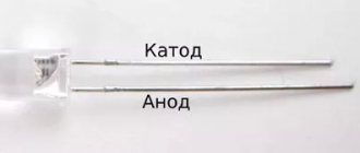
What is “L” LED
The Arduino Uno has rows of female connectors on the sides of the board, which are used to connect peripheral electronic devices or “shields”.
In addition, the board has a built-in LED, which you can control using sketches. We will conventionally call this built-in LED “L” LED, as is customary on many English-language resources.
The location of this LED on the board is marked in the photo below.
Installing Arduino libraries
Let's say we downloaded the library. You need to unzip it and put it in the folder:
64-bit version of Windows – C:Program Files (x86)Arduinolibraries 32-bit version of Windows – C:Program FilesArduinolibraries
As an example, a library for a display on a TM1637 chip, see screenshot
In the libraries folder there should be a TM1637 folder, in which there is an examples folder, and two files with the extensions .h and .cpp. These two files should be in every library.
ATTENTION, A COMMON ERROR WHEN INSTALLING LIBRARIES! Look carefully at the screenshot above: the library always contains files with .h and .cpp extensions (or they are located in the src folder), as well as an examples folder and sometimes a keywords file. So there you go! These library files should be in a folder that is in the libraries folder, not in a subfolder! Simple example: C:Program Files (x86)ArduinolibrariesGyverButton(library files) – CORRECT C:Program Files (x86)ArduinolibrariesGyverButtonGyverButton-master(library files) – INCORRECT
Board specifications
| Nutrition | 5 V |
| Input signal | 7-12 V (DC) |
| Number of DP | 14 (6 for PWM) |
| Number of APs | 8 |
| Maximum current DP | 40 mA |
| Flash format memory | 16 / 32 KB |
| RAM | 1 / 2 KB |
| EEPROM format memory | 512 bytes / 1 KB |
| Microcontroller clock frequency | 16 MHz |
| Dimensions | Width - 19 mm, length - 42 mm |
| Weight | 7 g |
A detailed overview of the board's capabilities is provided in the Datasheet - technical documentation. Detailed characteristics and description of AN are also indicated there.
Useful tips when working with Arduino
Working with text files
When further working with Arduino, you will often have to deal with library files (look at the list of methods or write your own libraries), so you need to do two very important things: enable the display of file extensions and download Notepad++. Notepad++ is more convenient than a regular notepad and has a bunch of features, for example, it recognizes the “code language” and highlights syntax.
Next, you need to enable the display of file extensions so that you know what kind of beast is in front of you. Brief instructions for Windows 7 and 10.
After this, we make the necessary files open by default in Notepad++
Writing program text
Autoformatting – The Arduino IDE can automatically organize your code (this means indentation, line breaks and spaces). To auto-format, use CTRL+T on your keyboard, or Tools/AutoFormat in the IDE window. Use often to make the code beautiful (canonical, classic) and more readable for others!
Hiding parts of code - Collapse long functions and other pieces of code to save space and scrolling time. Enabled here: File/Settings/Enable Code Folding
Don't use the mouse! The higher your programming skill becomes, the less you will use your mouse (yes, just like in those movies about hackers). Use both hands to write and navigate code, here are some useful combinations and hacks that I use ALL THE TIME:
- Ctrl+← , Ctrl+→ – move the cursor left/right ONE WORD
- Home , End – move the cursor to the beginning/end of the line
- Shift+← , Shift+→ – select a character to the left/right of the cursor
- Shift+Ctrl+← , Shift+ Ctrl+→ – select a word to the left/right of the cursor
- Shift+Home , Shift+End – select all characters from the current cursor position to the beginning/end of the line
- Ctrl+Z – undo last action
- Ctrl+Y – repeat undone action
- Ctrl+C – copy selected text
- Ctrl+X – cut selected text
- Ctrl+V – paste text from the clipboard
- Ctrl+U – upload firmware to Arduino
- Ctrl+R – compile (check)
- Ctrl+Shift+M – open port monitor
Also, to move comments to the right side of the code, use TAB rather than SPACEBAR . Pressing TAB moves the cursor around some table, causing your comments to be set nicely at the same distance in half as many clicks!
Khaki with food
Power from pins - during the development of prototypes without a bradboard, there are always not enough pins to power sensors and modules. So, weak (with a current consumption of less than 40 mA) 5 Volt sensors can be powered from any pins! It is enough to form a pin as an output and apply the desired signal to it ( HIGH – 5 Volts, LOW – GND).
Example: we connect a three-pin sound sensor without using the 5V and GND pins
Powered by programmer plug. You probably wondered why there are 6 pins on the edge of the board on the Arduino NANO? This is the port for connecting the ISP programmer. What does it do on the list of life hacks? Here's a photo of the pinout, use it!
Energy saving
Use the Low Power energy saving library. Examples and description inside (video lesson not ready yet)
Paired with the library, make a few modifications: turn off the power LED and cut off the left leg of the voltage regulator. ATTENTION! You can cut the leg of the regulator only if the board is powered from a 3-5 Volt source into the 5V and GND pins.
Version nano v 3.0
This version is equipped with an ATmega328 microcontroller. Unlike its younger brother, it has twice the amount of non-volatile and flash memory. And it boasts a clock speed of 16 MHz.
It will be interesting➡ Review of the arduino uno board for Arduino
Characteristics
- Microcontroller: ATmega328
- Limit supply voltage: 5-20 V
- Recommended supply voltage: 7-12 V
- Digital I/O: 14
- PWM: 6 digital pins can be used as PWM pins
- Analog pins: 8
- Maximum current: 40 mAh from one pin and 500 mAh from all pins.
- Flash memory: 32 kB
- SRAM: 2 kB
- EEPROM: 1 kB
- Clock frequency: 16 MHz
Comparison table of most Arduino boards released to date.
Power connection
This microcontroller can be powered via the mini-USB port from a computer, power bank, or from an adapter connected to a power outlet. Also, the +5V pin is not only an output, but also an input. You can apply current to it and all this will work only on the condition that the voltage of the supplied current is strictly equal to five volts.
Expert commentary
Lagutin Vitaly Sergeevich
Engineer with a degree in Computer Software and Automated Systems, MEPhI, 2005–2010.
Ask a Question
You can also supply direct current with a voltage of 6 to 20 volts to the VIN pin. These are the limits! When a voltage of 20 volts is applied, the voltage regulator on the board will get very hot. The recommended voltage for power supply via the VIN pin is from 7 to 12 volts.
Answers to frequently asked questions
Can Arduino be flashed only once? No, several tens of thousands of times, everything depends on the flash memory resource. And it's quite big.
How to erase/do I need to erase the old firmware when loading a new one? The memory is automatically cleared during flashing. The old firmware will be automatically removed.
Is it possible to write two firmwares so that they work together? No, flashing the firmware deletes absolutely all old data.
Is it possible to “pull out” the firmware from an already flashed Arduino? Theoretically, it is possible, but only in the form of machine code, into which the C++ firmware is converted during compilation, i.e. This will NOT help you in ANY WAY unless you have a degree in low-level programming. So no, you can't.
In this instruction, as an example, we will consider getting started in the Windows operating system. For Microsoft operating systems (Windows 2000/Vista), the differences are minor, they mainly relate to the names of the tabs in the Device Manager. In other operating environments, such as Linux, FreeBSD, Mac OS X, etc., the setup procedure is significantly different. If you need to organize work with this software, we recommend looking for answers to questions on the developer’s main website //www.arduino.cc.
Pinout Nano v 3.0
As already written above, the board has 14 digital pins. They are marked on the board with a leading letter “D” (digital). They can be both an input and an output. The operating voltage of these pins is 5 V. Each of them has a pull-up resistor and a voltage below 5 volts applied to one of these pins will still be considered 5 volts (logical one).
Description and principle of operation of solenoids.
Read more
Formula for calculating capacitor resistance.
Read more
What is a Geiger counter and how to make one yourself.
Read more
The analog pins on the board are marked with a leading “A”. These pins are inputs and do not have pull-up resistors. They measure the voltage supplied to them and return a value between 0 and 1024 when using the analogRead() function. These pins measure voltage with an accuracy of 0.005 V.
Pulse width modulation (PWM)
If you look closely at the board, you can see a tilde (~) icon next to some of the digital pins. This icon means that this pin can be used as a PWM output. Some Arduino boards do not have this icon because manufacturers do not always find a place for this symbol on the board. Arduino nano has 6 PWM pins, these are pins D3, D5, D6, D9, D10 and D11. To use PWM, Arduino has a special function analogWrite().
Arduino nano pinout diagram.
Other pins
- rx0 and tx1 are used to transfer data over the serial interface.
- Pins D10 (SS), D11 (MOSI), D12 (MISO), D13 (SCK) are designed for communication via the SPI interface.
- There is also an LED built into the board at pin D13.
- A4 (SDA) and A5 (SCL) can be used to communicate with other devices via the I2C bus. You can read more about this interface on Wikipedia. The Arduino IDE has a built-in "wire.h" library for easier work with I2C.
It will be interesting➡ The most popular Arduino projects
Module power supply
Arduino Nano can work from different power sources, it can be connected either through a Mini-B USB computer, or from a regular unregulated 6-20 volts (pin 30), or regulated 5 volts (pin 27). The board will automatically select the highest voltage supply.
- Via mini-USB or microUSB when connected to a computer;
- Through an external power source, voltage 6-20V.
External power is stabilized thanks to LM1117IMPX-5.0 with a voltage of 5V. When connecting via USB, a Schottky diode is used.
Board elements
Arduino Nano consists of many elements, including:
- microcircuits;
- passive elements (resistors, capacitors, diodes);
- connectors;
- regulators.
FT232R board chip
The chip allows you to connect the board via USB. The chip installed in the AN cannot work directly with the USB interface, so the FT232R converts it to a UART interface.
The heart of the platform is the ATmega328P microcontroller
ATmega328P is the main control element of the board. A sketch written by the programmer is loaded into it, and the controller sends commands to various elements of the board. For example, a microcontroller causes diodes to blink, relays to switch, and a piezoelectric element to make sounds.
LED indication
There are 4 LEDs built into the board, each of which has its own purpose:
- The RX and TX LEDs blink when data is being transferred via the UART.
- The L-diode lights up when a high signal level is applied to it, and turns off when the signal level is low.
- The ON LED lights up when there is power on the board.
Additionally, almost any pin of the microcontroller can be connected to other LEDs, 7-segment indicators or even displays.
Mini-USB connector
Using the mini-USB connector, the board can be connected to a personal computer. The AN can also receive power from external sources through this interface.
Linear Buck Voltage Regulator 5V
The LM1117MPX-5.0 microcircuit is used as a regulator. It converts the AN power signal into a power signal for the ATmega microcontroller and other logic elements that do not support power supplies greater than 5 V. For example, transistor-transistor logic (TTL) elements are powered by a signal of this magnitude.