Working with metal is difficult if you don’t have such a useful device as a welding machine at hand. With its help, you can not only cut, but also connect different layers of iron. The thickness and dimensions of the iron do not play a special role. Because a powerful welding machine can handle any metal. But such a device today is not very cheap. And therefore it is better to think about making it yourself. The device will be in no way inferior to store-bought analogues. And the main advantage is, of course, the opportunity to save money by avoiding an expensive purchase. Making your own welding machine will not be difficult if you know how to organize the work correctly.
Design and principle of operation of the simplest welding machines
To obtain a stable welding arc, which will allow you to weld metal of different thicknesses, currents in the range of 70 - 150 A are required. If you use devices designed for a voltage of 220 V, then they must consume high power, in the range of 15 - 30 kW. Therefore, such installations will be cumbersome, and it will not be possible to work with them normally. But at home it will simply be impossible to connect them; standard networks are not designed for such a load.
Therefore, the main task in the design and assembly of welding machines is to provide the required current while reducing power consumption. This is only possible when performing welding work with reduced voltage on the electrodes.
The simplest welding machine has the following design:
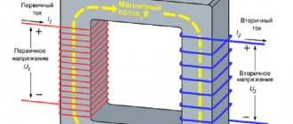
- A step-down transformer that reduces the voltage to the limits of 55 - 70 V and at the same time increases the current strength to the required parameters. Thanks to this, it is possible to reduce energy consumption to reasonable limits.
- Current is supplied from the transformer to the electrode and the workpiece using special welding cables. They are distinguished by a larger cross-section and reinforced insulation, allowing them to work with high currents.
- For welding, you will need electrodes installed in the holder. Thanks to the coating used, they simplify the ignition and maintenance of the electric arc, which becomes the source of thermal energy necessary for melting the metal.
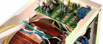
Welding transformer
There are no complex devices in the design of such welding machines. But during design, it is necessary to calculate the basic parameters, otherwise connecting inappropriate equipment to the network will lead to its failure, short circuits on the line, or it will simply be impossible for them to cook.
Features of winding windings.
There are the following rules for winding the windings of a welding machine:
- Winding should be done along an insulated yoke and always in the same direction (for example, clockwise).
- Each winding layer is insulated with a layer of cotton insulation (fiberglass, electrical cardboard, tracing paper), preferably impregnated with bakelite varnish.
- The terminals of the windings are tinned, marked, secured with cotton braid, and a cotton cambric is additionally put on the terminals of the network winding.
- If the wire insulation is of poor quality, winding can be done in two wires, one of which is a cotton cord or cotton thread for fishing. After winding one layer, the winding with cotton thread is fixed with glue (or varnish) and only after it has dried, the next row is wound.
The network winding on a rod-type magnetic core can be positioned in two main ways. The first method allows you to obtain a more “hard” welding mode. The network winding consists of two identical windings W1, W2, located on different sides of the core, connected in series and having the same wire cross-section. To regulate the output current, taps are made on each of the windings, which are closed in pairs.
The second method of winding the primary (network) winding involves winding a wire on one side of the core. In this case, the welding machine has a steeply falling characteristic, welds “softly”, the length of the arc has less influence on the value of the welding current, and therefore on the quality of welding.
After winding the primary winding of the welding machine, it is necessary to check for the presence of short-circuited turns and the correct number of turns. The welding transformer is connected to the network through a fuse (4...6 A) and if there is an AC ammeter. If the fuse burns out or gets very hot, this is a clear sign of a short-circuited turn. In this case, the primary winding must be rewound, paying special attention to the quality of the insulation.
If the welding machine makes a loud noise and the current consumption exceeds 2...3 A, then this means that the number of turns of the primary winding is underestimated and it is necessary to wind up a certain number of turns. A working welding machine should consume no more than 1..1.5 A current at idle, not get hot and not make a strong buzz.
The secondary winding of the welding machine is always wound on both sides of the core. According to the first winding method, the secondary winding consists of two identical halves, connected counter-parallel to increase the stability of the arc (Fig. 6 b). In this case, the wire cross-section can be taken slightly smaller, that is, 15..20 mm2. When winding the secondary winding using the second method, first 60...65% of the total number of its turns is wound on the side of the core free from windings.
This winding serves mainly to ignite the arc, and during welding, due to a sharp increase in magnetic flux dissipation, the voltage on it drops by 80...90%. The remaining number of turns of the secondary winding in the form of an additional welding winding W2 is wound on top of the primary. Being a power supply, it maintains the welding voltage and, consequently, the welding current within the required limits. The voltage across it drops in welding mode by 20...25% relative to the no-load voltage.
Winding the windings of a welding machine on a toroidal core can also be done in several ways.
Methods for winding the windings of a welding machine on a toroidal core.
| 1. Uniform; | 2. Sectional; |
| a - network winding; | b - power winding |
Switching windings in welding machines is easier to do with the help of copper tips and terminals. Copper lugs at home can be made from copper tubes of a suitable diameter with a length of 25...30 mm, securing the wires in them by crimping or soldering. When welding under different conditions (high or low current network, long or short supply cable, its cross-section, etc.), by switching the windings, the welding machine is adjusted to the optimal welding mode, and then the switch can be set to the neutral position.
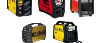
Types of welding machines
There are several main types:
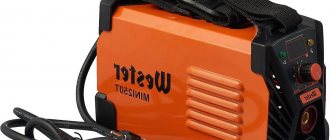
Welding transformer. A step-down transformer is used for the converter.
Welding transformer
Welding inverter. An inverter power supply with PWM serves as a converter here.
Welding rectifier. This is the same as a welding transformer, only it has a diode or thyristor rectifier in the secondary circuit.
Welding rectifier
Semi-automatic Welding is carried out in an inert environment; a gas cylinder is used for this.
Also read: Is it possible to connect copper and aluminum wires?
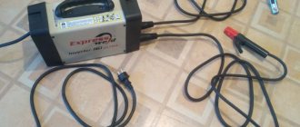
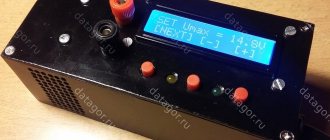
Diagnostics of a homemade inverter and its preparation for operation
Making an inverter welding machine is half the battle. An equally important task is its preparation for work, during which the correct functioning of all elements is checked, as well as their settings.
The first thing you need to do when checking a homemade welding inverter is to apply a voltage of 15 V to the PWM controller and one of the cooling fans. This will allow you to simultaneously check the functionality of the controller and avoid overheating during such a test.
Checking the output voltage with a tester
After the capacitors of the device are charged, a relay is connected to the electrical supply, which is responsible for closing the resistor. If you apply voltage directly to the resistor, bypassing the relay, an explosion may occur. After the relay operates, which should happen within 2-10 seconds after applying voltage to the PWM controller, you need to check whether the resistor has shorted.
When the relays of the electronic circuit operate, rectangular pulses should be generated on the PWM board and supplied to the optocouplers. This can be checked using an oscilloscope. The correct assembly of the diode bridge of the device also needs to be checked; for this, a voltage of 15 V is applied to it (the current should not exceed 100 mA).
The transformer phases may have been incorrectly connected when assembling the device, which can lead to incorrect operation of the inverter and the generation of strong noise. To prevent this from happening, the correct phase connection must be checked using a dual-beam oscilloscope. One beam of the device is connected to the primary winding, the second to the secondary. The phases of the pulses, if the windings are connected correctly, should be the same.
Using an oscilloscope to diagnose an inverter
The correct manufacturing and connection of the transformer is checked using an oscilloscope and connecting electrical devices with different resistances to the diode bridge. Based on the noise of the transformer and the readings of the oscilloscope, they conclude that it is necessary to improve the electronic circuit of the homemade inverter apparatus.
To check how long you can continuously work on a homemade inverter, you need to start testing it from 10 seconds. If the device’s radiators do not heat up during operation for such a duration, you can increase the period to 20 seconds. If such a time period does not negatively affect the condition of the inverter, you can increase the operating time of the welding machine to 1 minute.
Simplified welder calculation diagram
In practice, calculations are made based on the type and diameter of the electrodes used. Yes, there are more complex and accurate calculation formulas, but they are rarely used by amateurs. To obtain a stable and productive arc, it is necessary to obtain a current with the following indicators:
- For electrodes with a diameter of 2 mm, 30 - 80 A is sufficient.
- When the diameter increases to 3 mm, the current should increase to 70 - 130 A.
- For 4 mm electrodes, the value is set to 110 - 170 A.
- 5-mm electrodes are cooked at a current of 150 - 200 A.
The difference in current values is due to working with metals of different thicknesses and physical properties.
When making a welding machine yourself, you most often have to be content with a magnetic core from other devices, which is available. Therefore, the simplest calculation will be performed based on these two known characteristics - the cross-section of the magnetic circuit and the required current strength on the secondary winding.
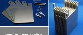
Please note that it is preferable to use rod-type cores to assemble the transformer. Compared to armored ones, they provide a higher current density in the windings and have increased efficiency.
Types of magnetic circuits
In addition, the location of the windings on the arms of the core is also important. If the primary and secondary windings are separated into different rods, this will lead to increased magnetic dissipation due to the increased air gap. Therefore, it is considered preferable to place a part of both windings on both one and the other rod.
In this case, to determine the required number of turns of the primary winding, use the following formula:
N1 = 7440 × U1/(Sout × I2)
Where
N1 - estimated number of turns;
U1 - mains voltage (200-240V);
Siz is the cross-section of the existing magnetic circuit;
I2 is the required welding current.
Please note that for devices with spaced windings, a different formula is used:
N1 = 4960 × U1/(Sout × I2)
If you have to carry out work under conditions of unstable voltage in the network, it makes sense to calculate the number of turns for the main values - 180, 190, 200, 220 and 240 V. When winding the wires, simply make taps at these values, which will allow you to select a stable operating mode for the transformer in any conditions.
The required number of turns of the secondary winding is calculated using the following simplified formula:
N2 = 0.95 × N1 × U2/U1
Where
N1 - estimated number of turns;
U1 - mains voltage (200-240V);
U2 - required no-load voltage on the secondary winding (50 - 70 V).
Also read: 11 effective ways to connect wires
For the primary winding, choose an insulated copper wire with a cross-section in the range of 5 - 7 square meters. mm, it is enough to work with a household single-phase electrical network. When choosing, pay attention to the heat-resistant properties of the insulation; it must withstand significant heat, which cannot be avoided.
The secondary winding is wound with a thicker wire, which is associated with a significant current strength that will flow through it. The best option would be a copper bus with a cross-section of at least 30 square meters. mm.
Microwave power supply
The considered welding machine circuit after assembly should produce a minimum of 4 kW; if we take the element from a microwave oven, which has a rating of 1.2 kW, as the main part, it will not be enough.
For operation, two transformers should be selected, which will subsequently need to be connected to each other.
The detailed algorithm of actions looks like this:
- By powering two parts to a 220-volt network, the integrity of the winding is checked.
- To remove the high-voltage winding, you need to cut the magnetic core.
- The coil is removed from the chain.
- From a copper bus of 10 sq. mm the core is manufactured.
- A dielectric spacer is created under the primary winding.
- The coil and magnetic circuit are connected.
- All cables are connected in accordance with the diagram.
After installing the electrode in the holder, you can begin to check the functionality of the created unit; there is no need to take markings with a diameter of more than 4-5 mm.
Welding transformer - the simplest type of equipment
To perform most welding work at home, a step-down welding transformer is sufficient without additional circuits or devices. The assembly sequence of such a unit is as follows:
- Divide the total number of turns of each winding into two equal halves to place them on both core bars.
- If you assemble a core from individual plates, you will need to fix them with ties or in a simple cage. The plates should not be isolated from each other.
- For the coils, a frame is made of thick electrical cardboard. The internal size must correspond to the cross-section of the core and must allow the coil to be moved up or down.
- The windings are wound by laying the turns close to each other. If necessary, make several rows of laid wire.
- If the primary winding is designed with taps, then a loop is made on the required number of turns and brought out without cutting it.
- The primary winding is placed on the lower part of the core, the secondary winding is attached to the top.
- To change the current strength for welding metals or when working with parts that differ in thickness, a simple regulator is provided. It will move the secondary winding coils up and down.
- The operating principle of such a regulator is based on changing the air gap between the windings. As a result, the parameters of the magnetic field change, which leads to an increase or decrease in the current strength in the secondary winding.
- The regulator is a threaded screw, which, when tightened, raises the coils. To do this, these elements are connected to each other.
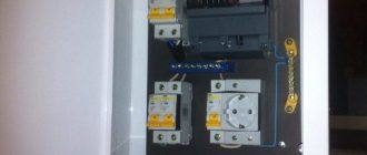
In almost all cases, homemade welding equipment is made without a housing. This is done to prevent overheating of the coils, which can cause the device to fail. If you make a circuit with forced cooling using a fan, then the welding transformer can be installed in the housing. For its manufacture, temperature-resistant, fireproof materials are chosen, for example, textolite with a thickness of 1.5 - 2 cm.
Studs are placed on the surface of the housing for connecting welding cables and network wires. The ability to connect to the taps of the primary winding is ensured by arranging separate contacts or installing a powerful packet switch to the required number of positions.
Also read: How to make a phase indicator with your own hands
How to make a welding unit with your own hands?
After studying the main features of the assembly process, you can proceed directly to assembling homemade equipment.
Today, there are a large number of different methods and recommendations on how best to assemble a homemade welding machine of any kind - with alternating or direct current, pulsed or inverter, automatic or semi-automatic.
There is no need to go deep enough into this topic, since one of the easiest ways to assemble a welding machine with your own hands is to use a transformer.
Its peculiarity is that it works with alternating current, which ensures the creation of a high-quality seam when welding metal surfaces. Such equipment can cope with any household work where it is necessary to weld metal or steel structures
To make it you need to prepare:
- Several meters of cable with great thickness.
- Material for the core that will be located in the transformer. The material itself must have increased permeability with magnetization.
The best option is when the rod-shaped core has the letter “P”. In some cases, it is allowed to use this part in a more modified form, for example, a round stator made from a damaged electric motor.
However, it is worth paying attention that it is more difficult to wind windings onto this shape. It is best when the core cross-section for classic welding equipment, made by hand and used for domestic purposes, had an area of about 50 cm2.
In order for the equipment to have an accessible weight, it is not necessary to increase the cross-section in volume, however, the technical effect will not be at the highest level. If the cross-sectional area does not suit you, then you can calculate it yourself using special diagrams and formulas.
The primary winding must be made of copper wire, which will have increased characteristics: thermal resistance, since during operation of the structure this part heats up very much.
Such a part must have cotton or fiberglass insulation. As a last resort, it is possible to use rubber insulated wire or rubber cloth, but beware of PVC winding.
The insulation is also made by hand, using cotton or fiberglass, or rather parts of it 2 cm wide. Thanks to these pieces, you can wrap the wire and then impregnate it with any varnish for electrical purposes. This insulation will not overheat after regular use.
Similar to the above calculations, it will be possible to calculate which cross-sectional area of the winding - primary and secondary - will be the most optimal. Often the secondary winding has an area of about 30 mm2, and the primary winding up to 7 mm2, using a rod of 4 millimeters in diameter.
In addition, in a simple way you need to determine how far a piece of copper wire will stretch and how many turns will be needed to wind two windings. After this, the coils are wound, and the frame is made using the geometric parameters of the magnetic core.
The main thing is to ensure that there are no difficulties when putting on the magnetic core. First of all, you need to choose the correct core size. It is best made using electrical cardboard or textolite.
Using the same analogue, it will be possible to make a structure for welding small parts. For home use, you can use a small mini welding machine.
Welding rectifier - features of operation and assembly
To perform certain types of welding work, for example, with stainless steel, the use of alternating current supplied by a transformer is not used. To work with such metals, a constant voltage supply is required. In addition, direct current cutting reduces the consumption of electrodes, and metal spattering is prevented during welding.
To perform work in such conditions, welding rectifiers are used, which allow welding with direct and reverse polarity current. If you have experience in installing electronic circuits, then you can also assemble such a device yourself.
The basis of the welding rectifier will be the same step-down transformer. The difference lies in the presence of a rectifying electronic circuit. If desired, you can remake the already described welding transformer or assemble a universal device that will allow you to weld with both alternating and direct current.
The simplest diagram of the electronic part of a welding rectifier looks like this:
Schematic diagram of a welding rectifier
When assembling such devices, the following design features should be taken into account:
- The main part of the device is a rectifier bridge made of powerful power diodes. They are connected according to the diagram, taking into account polarity.
- Smoothing of current ripple is carried out due to a filter made on the capacitor and choke coil. Please note that the components must have a margin of 2.5 - 3 permissible voltage.
- When working with high currents, the elements heat up. Semiconductor diodes are sensitive to overheating. Therefore, they are installed on radiators, which will increase the intensity of heat removal.
- When enclosing the device in a housing, it becomes mandatory to use a fan to increase cooling efficiency.
We pay attention to the connection of individual elements of the circuit. Considering that they will be exposed to high current, it is necessary to ensure reliable contact. If this is not done, then the wires in these areas will heat up and burn out. The preferred option is with fastening using platforms with a bolt and nut.
The choke in such designs is made in the form of a separate remote inductor, which is connected as needed. Note that installing a rectifier does not prevent the welding current from changing using the secondary winding coil position regulator.
As you can see, there are no difficulties in assembling a welding machine yourself. But it’s worth working on such devices only if you have experience in designing simple devices that operate with lower currents. Otherwise, entrust the assembly to a specialist or buy a factory welding machine.
Microwave welding machine:
Possible details when creating a welding machine
Welding rectifier circuit.
When creating a welding machine with your own hands, the stability of the electric arc is achieved by constant potential. The stability of the arc ensures the quality of the resulting seams. Constant potential is achieved by using high-power rectifiers, which are carried out on diodes that can withstand currents of up to 200 A, such as, for example, the B-200.
These diodes are large in size and require mandatory use to organize high-quality heat removal from massive radiators. This circumstance must be taken into account when manufacturing the structure body. The best option when creating a design would be to use a special diode bridge. The diodes can be mounted in parallel, which significantly increases the output current.
When assembling a structure with your own hands, you need to adjust all its components. If the selection is poor or incorrectly calculated, the design can affect the quality of welding.
Sometimes, with the appropriate selection of parts and components, a truly unique device can be obtained, which has a soft and easy ignition of the electric arc, and parts can be welded even with very thin walls, with almost no splashing of liquid metal.
AC assembly example
Click on the first photo and see the assembly sequence:
Maintenance of a homemade welding inverter
In order for the inverter device to serve for a long time, it must be properly maintained.
If your inverter stops working, you need to open its cover and blow out the insides with a vacuum cleaner. Those places where dust remains can be thoroughly cleaned with a brush and a dry cloth.
The first thing you need to do when diagnosing a welding inverter is to check the voltage supply to its input. If there is no voltage, you should check the functionality of the power supply. The problem in this situation may also be that the fuses of the welding machine have blown. Another weak link of the inverter is the temperature sensor, which, in the event of a breakdown, must not be repaired, but replaced.
A temperature sensor that often fails, usually located on a diode block or inductor
When performing diagnostics, it is necessary to pay attention to the quality of connections of the electronic components of the device. You can identify poorly made connections visually or using a tester. If such connections are identified, they must be corrected in order to avoid future overheating and failure of the welding inverter.
Only if you pay due attention to the maintenance of the inverter device can you count on it to serve you for a long time and enable you to perform welding work as efficiently and efficiently as possible.
Wire sizes
The device will work quite well with an output voltage of 60 volts and a current of up to 160 amperes. Calculations show that for the primary winding you need to take a copper wire with a cross-section of 3, or better yet, 7 square millimeters. For aluminum wire, the cross-section should be 1.6 times larger.
It is necessary to use fabric insulation for the wires because the wires get very hot during operation and the plastic will simply melt.
The primary winding must be laid very carefully and carefully because it has many turns and is located in a high voltage zone. It is desirable that the wire be without breaks, but if the required length is not at hand, then the pieces must be securely connected and soldered.