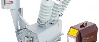
Hello, dear readers of the site. Let's continue the topic of resistors. In the first part of the article we got acquainted with constant resistance resistors (fixed resistors), and in this part of the article we will talk about variable resistance resistors , or variable resistors
.
Variable resistance resistors
, or
variable resistors
are radio components whose resistance can be
changed
from zero to the nominal value.
They are used as gain controls, volume and tone controls in sound-reproducing radio equipment, are used for precise and smooth adjustment of various voltages and are divided into potentiometers
and
trimming
resistors.
By purpose
Let's consider more types of resistors according to their intended purpose. They are of general and special purpose. General purpose resistors have the following parameters:
- nominal from 1 Ohm to 10 MOhm,
- power from 0.125 W to 100 W,
- accuracy tolerance of at least 20%, 10%, 5%, 2% or 1%.
They are suitable for operation in networks with voltages of no more than 1000 V. They are used as current limiters or as loads for active circuit elements. Special-purpose resistors are superior to “regular” ones in one or more characteristics. These include:
- Manufactured with high precision (maximum permissible deviation of the nominal value is 1%), having high stability of parameters. They are called precision and ultra-precision.
- High frequency. They have a very small intrinsic capacitance, which is why they are used in high-frequency circuits.
- High voltage (for networks with voltages above 1000 V).
- High resistance. The rating is above 100 MOhm and the voltage is at least 400 V.
To repair household appliances, elements with normal characteristics are sufficient. In general, when replacing, you should adhere to the rule: install an element of the same denomination and with the same characteristics. If the element base is old and it is difficult to find exactly the same copy or it costs disproportionately, we look for an analogue. When selecting analogues, we choose the same denomination, but the characteristics may be a little better. You should not take anything worse, as this may cause the devices to malfunction.
Potentiometers.
Potentiometers are used as smooth gain controls, volume and tone controls, serve for smooth adjustment of various voltages, and are also used in tracking systems, in computing and measuring devices, etc.
A potentiometer is an adjustable resistor that has two permanent terminals and one movable one. The permanent terminals are located at the edges of the resistor and are connected to the beginning and end of the resistive element, forming the total resistance of the potentiometer. The middle terminal is connected to a movable contact, which moves along the surface of the resistive element and allows you to change the resistance value between the middle and any extreme terminal.
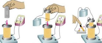
The potentiometer is a cylindrical or rectangular body, inside of which there is a resistive element made in the form of an open ring, and a protruding metal axis, which is the handle of the potentiometer. At the end of the axis there is a current collector plate (contact brush) that has reliable contact with the resistive element. Reliable contact of the brush with the surface of the resistive layer is ensured by the pressure of a slider made of spring materials, for example, bronze or steel.
When the knob is rotated, the slider moves along the surface of the resistive element, as a result of which the resistance changes between the middle and extreme terminals. And if voltage is applied to the extreme terminals, then an output voltage is obtained between them and the middle terminal.
The potentiometer can be schematically represented as shown in the figure below: the outer terminals are designated by numbers 1 and 3, the middle one is designated by number 2.
Depending on the resistive element, potentiometers are divided into non-wire and wire-wound .
1.1 Non-wire.
In non-wire potentiometers, the resistive element is made in the form of a horseshoe
or
a rectangular
plate of insulating material, on the surface of which a resistive layer is applied, which has a certain ohmic resistance.
Horseshoe Resistors
resistive element have a round shape and rotational movement of the slider with a rotation angle of 230 - 270°, and resistors with
a rectangular
resistive element have a rectangular shape and translational movement of the slider. The most popular resistors are the types SP, OSB, SPE and SP3. The figure below shows a SP3-4 type potentiometer with a horseshoe-shaped resistive element.
The domestic industry produced potentiometers of the SPO type, in which the resistive element is pressed into an arcuate groove. The body of such a resistor is made of ceramic, and to protect against dust, moisture and mechanical damage, as well as for electrical shielding purposes, the entire resistor is covered with a metal cap.
Potentiometers of the SPO type have high wear resistance, are insensitive to overloads and are small in size, but they have a drawback - the difficulty of obtaining nonlinear functional characteristics. These resistors can still be found in old domestic radio equipment.
1.2. Wire.
In wirewound potentiometers, the resistance is created by a high-resistance wire wound in one layer on a ring-shaped frame, along the edge of which a moving contact moves. To obtain reliable contact between the brush and the winding, the contact track is cleaned, polished, or ground to a depth of 0.25d.
The structure and material of the frame is determined based on the accuracy class and the law of change in resistance of the resistor (the law of change in resistance will be discussed below). The frames are made of a plate, which, after winding the wires, is rolled into a ring, or a finished ring is taken, on which the winding is laid.
For resistors with an accuracy not exceeding 10 - 15%, the frames are made of a plate, which, after winding the wires, is rolled into a ring. The material for the frame is insulating materials such as getinax, textolite, fiberglass, or metal - aluminum, brass, etc. Such frames are easy to manufacture, but do not provide precise geometric dimensions.
Frames from the finished ring are manufactured with high precision and are mainly used for the manufacture of potentiometers. The material for them is plastic, ceramics or metal, but the disadvantage of such frames is the difficulty of winding, since special equipment is required to wind it.
The winding is made of wires made of alloys with high electrical resistivity, for example, constantan, nichrome or manganin in enamel insulation. For potentiometers, wires made of special alloys based on noble metals are used, which have reduced oxidation and high wear resistance. The diameter of the wire is determined based on the permissible current density.
Classification according to operating conditions
According to the features of application and use, types of resistors are divided into groups.
Permanent
The resistance is constant with an acceptable normalized error and corresponds to the standard. On the electrical diagram they are depicted as a rectangle with sides 10x4 mm. Lead lines are drawn from the center of the narrow side. Next to the image they place the letter “R” with the serial number of the case according to the diagram. The denomination value is indicated here.
The scattering fits inside the rectangle. In imported technical documentation it is often depicted as a zigzag line connecting the terminals.
Variables and tuning
The components of a variable potentiometer are equipped with three or more terminals, and a mechanism for moving a slider - a current collector. The range of change extends from zero to a maximum limited by the set nominal value.
Changing the characteristics of the equipment during operation, such as adjusting the tuner, adjusting the volume level or lighting, is performed by a variable component.
The mechanism for moving the slider ends with a handle that allows for quick adjustments. If the setting is performed during commissioning and should not change daily, trimmers are used. The position of the current collector in them is set with a screwdriver.
Nonlinear
Automation and electronic protection devices actively use semiconductor nonlinear devices, the conductivity of which changes automatically with fluctuations in external environmental factors. The negative temperature coefficient of thermistors increases conductivity as the temperature increases and decreases as the temperature decreases.
A device with a positive TCS is called a posistor. In a photoresistor, the conductivity of the semiconductor layer increases with increasing illumination in the visible, infrared or ultraviolet spectrum.
Varistors are capable of increasing conductivity when the voltage applied to it increases
Magnetoresistors react to a magnetic field, and tensistors record the mechanical force applied to them.
Color marking on the resistor housing
When it appeared, I tried to remember the color marking and even memorize it - but nothing good came of it, I still got confused, and the resistor value had to be determined with a tester. Now I don’t remember when, but in one magazine I came across an article on how this whole thing can be avoided. There they talked about a cheat sheet made in the form of a resistor, only instead of colored stripes there are wheels on which the colors involved in designating the resistor values are written. Let's just look at the example shown in the photograph. Let's say we have a resistor with the following colors: green - blue - red. We need to determine its value:
With the first wheel you select the color of the first stripe (green), with the second wheel you select the color of the second stripe (blue), and with the third wheel you select the color of the third stripe (red) - this will be our multiplier. Now we multiply the resulting figure in the first two windows, and we got 56, by the factor obtained in the third window - that’s ten squared or 100. The result is 5600 Ohms or 5.6 kOhms. As you can see, the cheat sheet is very simple to use.
Color marking of domestic resistors
The end result will always be in Ohms, but it is not difficult to convert it to kiloohms or megaohms:
1000 Ohm is 1 kOhm; 10000 Ohm is 10 kOhm; 100000 Ohm is 100 kOhm; 1000 kOhm is 1 megaohm or 1,000,000 Ohms; 10 M is 10000 kOhm or 10000000 Ohm.
To make it, I used cardboard, but you can use any other material that is easy to process. If you use cardboard, then for strength it is advisable to glue it in two layers. I didn’t draw a drawing, but indicated all the dimensions directly on the cheat sheet, because it’s easier for me, and it’s clearer for you. Dimensions are indicated in millimeters.
The next step is to make three wheels. The first two will be the same, and they are marked with the colors of the stripes and the numbers corresponding to each color. The wheel must be divided into ten equal parts, and if you look at the right one, you can see that, for example, brown corresponds to one, and black corresponds to zero.
The sequence is:
- Black – 0;
- Brown – 1;
- Red – 2;
- Orange – 3;
- Yellow – 4;
- Green – 5;
- Blue – 6;
- Purple – 7;
- Gray – 8;
- White – 9.
Resistor with markings
Here the sequence is:
- Black – 1;
- Brown – 10;
- Red – 10 to the power of 2 (100);
- Orange – 10 to the power of 3 (1000);
- Yellow – 10 to the power of 4 (10000);
- Green – 10 to the power of 5 (100000);
- Blue – 10 to the power of 6 (1000000); Purple – 10 to the power of 7 (10000000);
- Gray – 10 to the power of 8 (100000000);
- White – 10 to the power of 9 (1000000000);
- Golden – 10 to the power of -1 (0.1);
- Silver – 10 to the power of -2 (0.01).
Secure the wheels with bolts with a diameter of 3 mm. In any case, if all else fails, the resistance of the resistor can always be measured with a multimeter. If you have any doubts about determining the band of the first number, refer to the tolerance band, which is located on the right side of the resistor. As a rule, the bulk of resistors come with a tolerance of five and ten percent, and these are golden and silver colors.
Resistor in the diagram
Trimmer potentiometers Murata series PVZ3A
| 1 kOhm | |
| PVZ3A152A01R00 | 1.5 kOhm |
| PVZ3A202A01R00 | 2 kOhm |
| 10 kOhm | |
| PVZ3A153A01R00 | 15 kOhm |
| PVZ3A503A01R00 | 50 kOhm |
| 100 kOhm | |
| PVZ3A504A01R00 | 500 kOhm |
| PVZ3A105A01R00 | 1 mOhm |
Packaging: In blister tape on a reel with a diameter of 180 mm, 2000 pieces of PVZ3AN trimming potentiometers.
How to test a resistor
Almost any multimeter is suitable for testing a resistor. With a fixed resistor, only two things can happen:
- The resistor breaks - its resistance tends to infinity;
- Strong change in resistance.
In the electrical circuit, it is easy to notice a burnt resistor - in this case, it should have been tested using a multimeter. It should be noted that a resistor break can occur without changing its appearance (without “burning”).
The resistor testing process is as follows:
- Determine resistance by digital or color markings;
- Set the multimeter to resistance measurement mode based on the resistor value;
- Check that the resistance matches that indicated on the housing.
If the resistor resistance is within acceptable limits (for carbon domestic resistors C1-4, permissible deviations from the nominal value can reach ±10%), then the resistor is in good condition. Otherwise, it needs to be replaced.
The process of testing fixed resistors using a digital multimeter is demonstrated in the video below.
Testing variable resistors is a little more complicated. It is necessary to check the quality of contact of the brush with the conductive element. In some cases, a faulty variable resistor can be repaired.
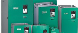
Production methods
A variable resistor can be of two types: wire-wound and film. In wire type, a wire is wound around a dielectric tube, and a metal movable contact—a slider—moves along it. Its location determines the resistance of the element. The turns of wire are laid close to each other, but they are separated by a layer of varnish with high dielectric properties.
Wirewound Slider Variable Resistors
Variable wirewound resistors are not necessarily a tube with wire wound around it, as in the photo above. Such elements were mainly produced several decades ago. Modern ones are not much different from film ones, except that the body is a little higher, since the wire still takes up more space than the film.
With the cover removed, the wire helix and slider are visible
In film variable resistors, a layer of conductive carbon is applied to the dielectric plate (usually made in the form of a horseshoe). In this case, the contact is also movable, but it is fixed to a rod in the center of the horseshoe and to change the resistance, you need to rotate the rod.
Film adjustable resistor
Adjustable variable resistance can be either wire or film, and tuning ones are mainly made of film. They have an external difference: there is no rod with a handle, but a flat disk with a hole for a screwdriver. Resistors of this type are used only for adjusting parameters during startup or maintenance of equipment.
Variable SMD Resistors
In addition to the production method, there are two more forms of release: for conventional surface mounting and SMD elements for surface mounting. SMD resistors are miniature in size and made using film technology.
Resistor values.
Resistor values are not arbitrary numbers. There are special series of ratings, which represent values from 0 to 10. So, resistor ratings (resistance values) can have values that are defined as the value from the corresponding series multiplied by 10 to the integer power. Let's look at the main rows - E3, E6, E12 and E24:
The number in the name of the series means the number of numbers in the series of denominations in the range from 0 to 10. In the E3 series there are three numbers - 1.0, 2.2, 4.7, similarly in other series. Thus, if the resistor is from the E3 series, then its nominal value (resistance) can be 1 Ohm, 2.2 Ohm, 4.7 Ohm, 10 Ohm, 22 Ohm, 47 Ohm... 1 KOhm... 22 KOhm, etc. There are also nominal series E48, E96, E192 - their difference from the series we considered is only that there are even more permissible values
Ohm's law
Ohm's law allows you to determine one of the quantities at a given section of the circuit: current I, voltage U, resistance R, if the other two are known:
To denote voltage, V is used along with the symbol U.
Consider a simple circuit
Let's calculate the current passing through resistor R1 and, accordingly, then through lamp L1. For simplicity, we will assume that the lamp itself has zero intrinsic resistance.
Likewise, if we had a 5V power supply and a lamp that was specified to operate at 20mA, we would need to select a resistor of the appropriate value.
In this case, the difference of 10 Ohms between the ideal rating and the existing one does not matter much: you can safely take the standard rating - 240 or 220 Ohms.
Likewise, we could calculate the required voltage if it were not known and we had the resistance values and the desired current in hand.
Notation system
All of the above features of the parameters are usually reflected in the full name of the potentiometer in the technical or product-production documentation.
Below is the designation system for variable resistors according to the current specifications.
Rice. 2.2. Designation system for variable resistors of domestic companies.
First element (letters and numbers)
denotes the resistor type and design option.
Second element (letter)
denotes the permissible power dissipation in watts.
Third element (numbers and letters)
denotes the nominal resistance.
Fourth element (numbers)
denotes the permissible deviation of resistance from the nominal value (in%).
Fifth element (letter)
denotes the dependence of the resistance of a variable resistor on the position of the moving contact.
Sixth element (numbers and letters)
denotes the type of protruding part of the shaft.
Seventh element (numbers)
indicates the size of the protruding part of the shaft.
Eighth element (letter)
denotes a delivery document.
Below we will consider the designation system for foreign resistors using the example of Bourns (Fig. 2.3).
First element (letters and numbers)
denotes a series (model) of a variable resistor.
Second element (digit)
denotes the number of sections (groups) of variable resistors (if there is only one section, then this element is missing).
Third element (number or letter)
indicates the location of the pins and their shape (Table 2.1.).
Fourth element (letter)
indicates the presence (“S”) or absence (“N”) of an additional switch (may be absent in the designation of some series of resistors).
Fifth element (numbers)
indicates the shaft length in mm.
Sixth element (numbers)
denotes the rated resistance code
Rice. 2.3. Bourns designation system for variable resistors.
Location of resistor terminals relative to the housing
A resistor (Latin resisto - resist) is one of the most common radio elements, and the variable resistor in a simple transistor receiver amounts to several tens, and in a modern TV - up to several hundred.
A variable resistor is a resistor in which the electrical resistance between the moving contact and the terminals of the resistive element can be changed mechanically.
Resistors act as load and current-limiting elements, voltage dividers, additional resistances and shunts in measuring circuits, etc. The main task of a resistor is to provide resistance, that is, to block the flow of electric current. Resistance is measured in ohms, kilo-ohms (1000 ohms) and mega-ohms (1,000,000 ohms).
Color coding of resistors.
Most resistors are color coded, like the one in this picture. It consists of 4 or 5 stripes (most often, although there can be, for example, 6) of certain colors, and each of these stripes carries a certain meaning. The first two stripes absolutely always indicate the first two digits of the nominal resistance of the resistor. If there are 3 or 4 stripes in total, then the third stripe will indicate the multiplier by which you need to multiply the number obtained from the first two stripes. When there are 4 bands on a resistor, the fourth will indicate the accuracy of the resistor. And in the case when there are only five bands, the situation changes somewhat - the first three bands mean three digits of the resistor resistance, the fourth is the multiplier, the fifth is the accuracy. The correspondence of numbers to colors is given in the table:
There is another important point here - which lane should be considered first? Most often, the first strip is considered to be the one that is located closer to the edge of the resistor. In addition, you can notice that the gold and silver stripes cannot be first, since they do not carry information about the value of resistance. Therefore, if the resistor has stripes of this color and they are located on the edge, then we can say for sure that the first stripe is on the opposite side. Let's look at a practical example:
Since we have 5 bands here, the first three indicate the resistance of the resistor. Having looked at the required values in the table, we get the value 510. The fourth band is the multiplier - in this case it is equal to 103. And, finally, the fifth band is the error - 10%. As a result, we get a resistor of 510 KOhm, 10%.
In principle, if you don’t want to deal with colors and values, then you can turn to some automated service that determines resistance by color markings. There you will only need to select the colors that are applied to the resistor and the service itself will display the resistance value and accuracy.
So, we’ve sorted out the color coding of resistors, let’s move on to the next question...
Video
Coffee capsule Nescafe Dolce Gusto Cappuccino, 3 packs of 16 capsules
1305 ₽ More details
Coffee capsules Nescafe Dolce Gusto Cappuccino, 8 servings (16 capsules)
435 ₽ More details
Rechargeable batteries
Variable resistors.
Structurally, variable resistors consist of a conductive surface with two ohmic contacts, essentially an open planar constant resistor, wire or carbon, and a contact sliding along it - a current collector.
The value of the electrical resistance of a variable resistor can be smoothly changed from zero to the nominal value. This is achieved by moving a sliding contact along a conductive surface.
The figure below shows a variable resistor without a back cover and its circuit designation.
The purpose of trimming resistors is to fine-tune the operating modes of electronic devices. Moreover, the setting position, as a rule, does not change throughout the entire further life of the device. Therefore, the sliding contact movement drive device is adapted to be adjusted using a screwdriver, and no special requirements are placed on the strength of the conductive layer.
Adjustment resistors are intended for regular use - for example, to change the volume level of sound-conducting devices. Their mechanical properties must meet special requirements - the conductive layer along which the current collector slides must be particularly resistant to mechanical stress. The drive for moving the sliding contact is equipped with an extended handle for greater ease of use.
Types and types of device
There are many types of trimming resistors on the market today. These are non-separable trimming resistors of type SP4-1, filled with epoxy compound, and intended for defense equipment, and trimmers of type SP3-16b for vertical mounting on a board.
It will be interesting➡ Description and principle of operation of solenoids
In the manufacture of household equipment, small trimming resistors are soldered onto the boards, which, by the way, can reach 0.5 watts in power. In some of them, for example in SP3-19a, metal ceramics are used as a resistive layer.
There are also very simple tuning resistors based on varnish film, such as SP3-38 with an open case, vulnerable to moisture and dust, and with a power of no more than 0.25 watts. Such resistors are adjusted with a dielectric screwdriver to avoid accidental short circuits. These simple resistors are often found in consumer electronics, such as monitor power supplies.
Some trimmer resistors have a sealed housing, for example R-16N2, they are adjusted with a special screwdriver, and are more reliable because dust does not get on the resistive track and moisture does not condense.
Powerful three-watt resistors of the SP5-50MA type in the case have holes for ventilation, in them the conductor is wound in the shape of a toroid, and the contact slider slides along it when the handle is turned with a screwdriver.
In some CRT TVs you can still find high-voltage trimming resistors, such as HP1-9A, with a resistance of 68 MOhm and a nominal power of 4 watts. Essentially, this is a set of cermet resistors in one package, and the typical operating voltage for this resistor is 8.5 kV, with a maximum of 15 kV. Today, similar resistors are built into TDKS.
In analog audio equipment you can find slider or slide variable resistors, such as SP3-23a, which are responsible for adjusting volume, timbre, balance, etc. These are linear resistors, which can also be double, such as SP3-23b.
What do linear resistors look like in a diagram?
Trimmer multi-turn resistors are often found in electronic equipment, measuring instruments, etc. Their mechanism allows you to precisely regulate the resistance, and the number of turns is measured in several tens.
The worm gear allows the sliding contact to turn slowly and move smoothly along the resistive track, allowing the circuits to be tuned very, very accurately.
It will be interesting➡ Diode bridge - what is it?
For example, the SP5-2VB multi-turn tuning resistor is adjusted precisely by means of a worm gear inside the housing, and to completely pass the entire resistive track you need to make 40 turns with a screwdriver. Resistors of this type in various modifications have a power from 0.125 to 1 watt, and are designed for 100 - 200 adjustment cycles.
This is not a complete overview of the types and types of parts. As we can see from the previous description, tuning resistors are inherently close to variables, but strictly speaking, they are not. This video briefly but clearly describes how to convert a trimmer resistor into a variable resistor.
Parameters and characteristics
There are a number of parameters that characterize the component in operation and they are necessarily taken into account by developers when selecting a radio component. Technical characteristics of resistors are available in reference literature. Let's dwell on the parameters that are written on the case or can be determined by appearance.
Denomination
The table shows the series whose number values are most often used in practice. The required denomination is formed from a table element with a decimal coefficient of the corresponding degree.
Tolerance
The largest difference between the actual value and the nominal value, expressed as a percentage, is called the tolerance or accuracy class. The manufacturer is obliged to provide the necessary tolerance according to the selected range of preferred values and bring the product to the required accuracy class.
For the E6 series, a value deviation of ±20% is allowed, for E12 ±10%, and E24 allows a manufacturing inaccuracy not exceeding ±5%. Normal operation of most circuits is ensured by radio components of class 5-10%. If it is necessary to use increased accuracy, this is indicated on the electrical diagram.
Power dissipation
For each model, the amount of heat dissipation is normalized. If during operation the heat generated exceeds the dissipation, the housing will heat up and subsequently fail. Developers carefully calculate the heat dissipation power of the radioelements used and indicate the values in the technical documentation.
For a homemade device, it is easy to calculate the required resistance value and dissipation.
For example: The LED is connected to a source with voltage U=9 V (volts). It is known that the operating voltage of the LED is Usv = 3.7 V, the operating current Isv = 5 mA (= 0.005 ampere). The LED and the resistor are connected in series, the current is the same.
We calculate the voltage that needs to be extinguished: Uр = Ui-Usv = 8-3.7 = 4.3 V.
Required: Rг=Uр/Iсв=4.3/0.005=870, the nearest one in the E24 row is equal to 910 Ohm.
We determine P=Uр*Isv=4.3*0.005=0.02 W (Watt)
Rule: The power of the installed element is selected to be one and a half to two times the calculated value. Suitable 910 ohms with 0.05 watt dissipation.
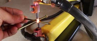
Cleaning the trimmer with regular alcohol
The resistor in circuits can become dirty; its slider track becomes covered with a layer of dust over time. And in order to return the electrical resistance to its previous performance, you just need to clean it.
Cleaning trimmer resistors is quite simple and quick. It is best to use pure alcohol for these purposes. It is better not to use various products such as nail polish remover, moonshine, or cleaners, as they may contain impurities that negatively affect the cleanliness of the resistor.
So, we disassemble the resistor (if it has a protective casing), for this it is usually enough to unbend the small metal clips on the resistor body itself, after which you need to remove this cover. Inside the resistor we will see a track along which the slider of the middle terminal of the resistor moves. It is this path that needs to be cleaned from dirt with alcohol.
It’s convenient to do this: take a syringe (let’s say 2 cc), fill it with alcohol, and carefully apply a few drops through the needle of the syringe directly onto the resistor track. After this, we begin to rotate this resistance in different directions so that the alcohol spreads throughout the entire track and thereby clears the way for the slider.
How to clean a resistor at home.
In principle, this is enough so that after assembling and installing the tuning resistor in our circuit workplace, we can enjoy its normal operation without previous problems. Although, if space on the resistor itself allows, you can also carefully go over it with a cotton swab, which will completely remove all dirt from the slider track.
Well, then we need to put our updated resistor back together and put it in our workplace. In most cases, after such cleaning, the electrical resistance is completely restored, and the intermittency of its operation disappears.
Difficult cleaning cases
In very rare cases, it is not a matter of dirt, but, for example, the destruction of this path as a result of excessive overheating. This can happen when too much voltage is accidentally applied to this resistor and the power of this resistor is not large enough to quickly dissipate the generated heat from the high current. This is where the variable resistor track heats up greatly, followed by its destruction. Cleaning with alcohol won't help here.
This resistor needs to be completely replaced with a new one that is known to work. And, of course, before installing a new resistor on the old circuit, check it so that the process of destroying the track does not repeat with a new resistance.
Unfortunately, not all types of variable and trimming resistors can be cleaned using the above method. Sometimes there is resistance in the solid body, which makes it impossible to reach the slider track.
Here you can go to extreme measures. Make a small hole in the body (with a 0.8-1 mm drill). Well, pour alcohol through it with a syringe through a needle. Next, again turn the resistor knob in different directions and then you need to wait until the alcohol has completely evaporated.
You can warm up this variable resistor a little (up to 50 degrees), this will speed up the evaporation of alcohol. Although pure alcohol is a dielectric, it does not conduct current through itself. Consequently, it will not negatively affect the operation of the variable resistor, even if there is some alcohol left on it, which will still evaporate.
Basic parameters of variable resistors
The parameters of variable resistors can be divided into two groups: parameters common to fixed resistors and special parameters characteristic only of variable resistors.
Parameters common to fixed resistors:
- ;
- ;
- ;
- ;
- ;
Special parameters for variable resistors:
- Functional characteristics
- Resolution
- Minimum resistance
- Wear resistance
Functional characteristics
Functional characteristic (taper) – dependence of the resistance of a variable resistor on the position of the moving contact. The functional characteristics of a variable resistor are:
- linear;
- nonlinear.
Variable resistors with a nonlinear characteristic are usually used in audio equipment to adjust the volume level, timbre, etc. The most widely used nonlinear characteristics are:
- logarithmic;
- inverse logarithmic.
A - linear (linear), B-logarithmic (Reverse Log, Reverse Audio), B-reverse logarithmic (Logarithmic, Audio) It is worth noting that the designation of functional characteristics in domestic documentation differs from foreign ones: the reverse logarithmic characteristic in foreign documentation is designated as Logarithmic.
Resolution
Resolution is the minimum change in resistance with minimal movement of the control knob. This parameter is applicable only to wirewound potentiometers and is determined by the resistance between adjacent turns. Non-wire potentiometers have very high resolution and are determined by defects in the resistive layer.
Wear resistance
Wear resistance is the ability of a potentiometer to maintain its parameters during operation. As a rule, it is expressed by the number of cycles of movement of the contact assembly during which the characteristics of the potentiometer remain within the specified limits.
WHAT RESISTORS AND WIRES TO USE IN A POWER AMPLIFIERWHAT CAPACITORS TO PUT INTO THE POWER AMPLIFIER
CONSTANT RESISTORS
First of all, a little reminder about the designations of resistors:
Like any other element, resistors have such a parameter as their own noise, which consists of thermal and current noise. Current noise is caused by the discrete structure of the resistive element. When current flows, local overheating occurs, as a result of which the contacts between individual particles of the conductive layer change and, consequently, the resistance value fluctuates (changes), which leads to the appearance of current noise between the terminals of the EMF resistor. Current noise, like thermal noise, has a continuous spectrum, but its intensity increases in the low-frequency region, and the magnitude significantly exceeds the magnitude of thermal noise. All these effects depend on the current density. The larger it is, the greater the manifestation of these troubles. Therefore, by connecting 2 resistors in parallel (increasing the cross-sectional area and reducing the current density), all these effects are reduced. The same can be done by taking a resistor of larger overall power. It has a larger cross-section of the conductive layer and the current density in it will be lower. By connecting 2 resistors in series, the noise adds up, so it is highly undesirable to use a series connection of resistors in cascades with a high gain. The total resistance of two resistors connected in parallel is calculated by the formula: This noise depends on many factors, including the design of the particular resistor, including the resistive material and especially the end connections. Here are the typical excess noise values of various types of resistors, expressed in microvolts per volt of voltage applied to the resistor (rms value measured over one decade of frequency):
Carbon composite 0.10 µV to 3.0 µV
Carbon film From 0.05 µV to 0.3 µV
Metal film From 0.02 µV to 0.2 µV
Wire-wired 0.01 µV to 0.2 µV
This noise has a spectrum of approximately 1 (constant power per decade of frequency) and is sometimes called pink noise. Noise arising from other causes also often has a spectrum 1; Examples of such noise are base current noise in transistors and cathode current noise in vacuum tubes. It is curious that value 1 occurs in nature in the most unexpected manifestations, for example, the speed of ocean currents, the flow of sand in an hourglass, the movement of trains in Japan, and the annual flow of the Nile over the past 2000 years. If you plot the loudness of a piece of classical music, you will again get a spectrum of 1! A general principle explaining the origin of noise with spectrum 1 has not been found, although it seems to be floating in the air, but in each individual case it is often possible to determine the source of such noise. In terms of noise, wirewound resistors are much more correct than all kinds of film and composite resistors, but they have a fairly large parasitic inductance. Thermal noise is strongly influenced by temperature and its own resistance, and although thermal noise is much less than current noise, you should not forget about it either. It is worth fighting resistor noise, theoretically, in all amplification paths, however, the greater the signal amplitude, the less the influence of resistor noise, therefore, special attention to resistor noise can be paid only in the first amplification stages, when the signal has an amplitude of up to 100 mV and it is advisable to think through these stages more carefully, protect from excess heat sources and provide cooling, for example by organizing ventilation holes. Resistors also have an additional parameter showing the change in resistance depending on temperature - the temperature coefficient of resistance (TCR), which characterizes the relative change in the resistance of the resistor when the ambient temperature changes by 1 °C. For non-wire resistors used in BREA, the TCR does not exceed ±0.04-0.2%, and for wire resistors - ±0.003-0.2%. As a rule, in power amplifiers, in the last stage of the voltage amplifier, 0.5 W resistors are used in the emitters of transistors. Typically, it is the last stage of the voltage amplifier that produces the maximum signal amplification. If the amplifier is symmetrical, then it is necessary to select not only the transistors of this stage according to the gain coefficient, but also a selection of identical resistors in their emitter circuits, namely selection
resistors with the same value. This measure will not negate the selection of transistors, since the final gain of the cascade depends on the value of the emitter resistor in a circuit with a common emitter. In addition to weakly powerful resistors, amplifiers use 2 or 5 W resistors installed in the emitters of the final stage. The type of these resistors quite often confuses beginners - ceramic low-resistance resistors abound on sale, but on forums it is often mentioned that they spoil the sound, since they contain a spiral made of a high-resistance alloy inside, and this is inductance.
Resistors recommended for use for these purposes are quite often in short supply, and sometimes sellers charge unreasonable prices for them:
However, it is not entirely clear on what basis the conclusions were made that C5-5 or C5-16 do not contain inductance, and the most striking example is mechanical opening:
The most acceptable option is to use MLT-2 resistors for these purposes, but the chances of getting rid of inductance are not one hundred percent - a spiral of the resistive layer is clearly visible on the top resistor:
Therefore, when purchasing MLT-2, you should pay attention to their appearance, and if it turns out that the resistive layer is in the form of a spiral, this is not at all a reason to panic - yes, there will be inductance, but its value is too small - for the resistor shown in the photo at 100 Ohms the inductance was 70 μH, and for resistors with a resistance of 1, 0.68, 0.47, 0.33 and 0.22 Ohms it will be tens of times less.
VARIABLE RESISTORS
In addition to fixed resistors, amplifiers use variables to adjust volume, balance, and, if necessary, timbre. The quality of these resistors mainly determines the additional noise introduced by the changing contact resistance between the resistive layer and the engine.
| There are quite a lot of variable resistors produced today, and there are also old-style resistors. |
In addition to other parameters, variable resistors have one more - group. This parameter shows by what law the resistance on the resistor motor changes depending on its position, for example, for rotor-type resistors this will be the angle of rotation. Domestic resistors have 3 main and two auxiliary groups:
Group A
- linear dependence of the change in resistance on the position of the engine, group
B
- logarithmic dependence,
C
- inverse logarithmic.
The most popular are “A” and “B”. “A” is used for linear adjustments, for example in thermostats, engine speed controllers. “B” is the best option for adjusting the volume, since the human ear perceives an increase in volume according to a logarithmic law. Auxiliary groups I
and
E
are usually used in pairs on dual resistors - one resistor of the "I" group, the second "E", which makes such a resistor ideal for adjusting the balance in stereo amplifiers. Imported variable resistors have 4 groups:
Here you should immediately pay attention to the fact that imported ones have group A
has an inverse logarithmic dependence, i.e.
To adjust the volume, resistors of group “A” are required, and group B
has a linear relationship.
Group W
is used to adjust the balance - usually the resistor slider is connected to the common wire, and the resistive layer acts as an attenuator, together with constant current-limiting resistors. On some subtypes of variable resistors intended for volume control, taps are made from the middle of the resistive layer; taps with a ratio of 1/ and 2/3 are made much less frequently. These resistors are convenient for implementing thin-compensated volume controls. Loudness compensation allows you to equalize the illusion of changes in the frequency response of the path at low and high volumes - at low volumes it seems that the low-frequency and high-frequency components of the signal are reduced, which is why a rise in low-frequency and high-frequency frequencies is introduced in the regulator itself. One of the circuit options for a loud-compensated volume control and changing its frequency response is given below:
There are two main types of variable resistors - rotor and slide. Both of them have many subspecies, so for brevity, only the popular ones are shown in the table:
| Variable resistor of the R12 series, there are double ones, there are with a switch. The closest structural neighbor is made on a textolite base. Widely used in portable audio equipment. Available for vertical and horizontal installation. Reliability leaves much to be desired. | |
| The R12XX series - the design consists of a getinaks “horseshoe” with an applied carbon resistive layer. For a better understanding, you should decipher the designation: R - ROTOR, i.e. rotary, the next two numbers indicate the diameter, but the rest is according to the specification. There are single and double ones. Widely used in portable audio equipment and low-price automotive applications. Available for vertical and horizontal installation. | |
| The RK11XX series, the RK14XX series of the same design, are available for vertical and horizontal installation, the first numbers after the letters indicate the size: , there are double and single ones, they are not very popular in portable audio equipment, but they do come across them. | |
| RK12ХХ are popular in stationary mid-price category and high-end portable equipment; they often appeared in car radios. There are single, double, quadruple. The size of a horseshoe with a resistive layer can reach 24 mm; of course, the first digits in the name will be 24. They can be equipped with a switch; some models of this type have a tap from the middle. To increase reliability and reduce resistance between the motor contact and the resistive layer, it is better to use larger diameter resistors if there are no size restrictions. | |
| Variable resistors of the slider type contain in their abbreviation either the first or second letter S - SLIDE. They can be single, double, with or without a center outlet. The first two numbers after the letters indicate the stroke length of the engine, for example, on the upper SL101 the engine moves 10 mm, and on the lower SL20V1 - 20 mm. Usually in the middle position the resistor slider is slightly fixed. | |
| The DACT and ALPS potentiometers are designed as a multi-position biscuit switch with installed SMD resistors. The resistor values provide an inverse logarithmic dependence of the change in resistance when the potentiometer axis is rotated. The contacts of the engine and the “horseshoe” are made of materials with increased wear resistance and provide the best contact for a VERY long time. Of course, the cost of such potentiometers is quite high. | |
| There is another group of potentiometers that can be called “successful”, and in the literal sense of the word - these are potentiometers taken from old power amplifiers of the zero complexity group. Just two months ago I SUCCESSFULLY purchased such a potentiometer from a junk dealer for only 50 rubles. Oily and dusty, but the contacts are in VERY good condition. | |
| The most popular resistors are discussed here. | |
WIRES AND CONNECTORS
After all the boards are ready, checked and washed, they need to be installed in the case and connected to each other, and this requires wires and “connectors”. The best connection is soldering, but this is not always convenient, and soldering can be different. If a solder connection is used, solder is required for soldering. In radio-electronic equipment (REA), lead-tin solders of three main grades are used: POS-40 - contains 40% tin and 60% lead, used... Yes, it would be better not to use... POS-60 - the most popular solder, used for mounting elements REA, contains 60% tin and 40% lead. It has good spreadability, being in a liquid state, over time it can acquire an oxide film and become dull; POS-90 is a solder consisting of 90% tin and almost 10% lead (the rest is technological impurities). Quite often called food grade, since the lead content is minimal and can be used for soldering household items that come into contact with food. The soldering quality is quite high, but a slightly higher temperature of the soldering iron is required. The copper tip of the soldering iron burns out much faster than when using POS-60. The surface of POS-90 practically does not oxidize due to moisture. There is another type of solder called lead-free or environmentally friendly. I didn’t even want to look for the chemical composition - most low-price electronic devices are sealed with this light-gray substance, it has a higher melting point compared to PICs, and being in a liquid state it has low wettability, which makes it difficult to service the leads of electronic components and reduces the quality of soldering. Mechanical properties at the POS-40 level. When soldering, fluxes are almost always used - substances that create a thin film on the surface of the parts being soldered, protecting against oxidation, which occurs much faster at high temperatures. There are quite a few chemical compositions of fluxes, most are based on ordinary pine rosin, which can be used for soldering on its own. To improve the quality of soldering, it is recommended to twist the stripped strands of stranded wires together as tightly as possible - this way, the maximum possible number of points of contact is created, which significantly reduces the contact resistance. It is highly undesirable to use connectors in the power part of the amplifier, even if they are self-clamping or screw-type. Such a connection automatically doubles the number of connections: 1. The connector is soldered to the board; 2. The wire is screwed to the connector. If male-female connectors are used, then the number of connections is tripled: 1. The male connector is soldered to the board; 2. Contact point of male-female mating parts; 3. The “female” connector is soldered to the wires. Of course, connectors greatly simplify access to the device modules, but they also reduce reliability, so it is better to use connectors only on low-current circuits and reduce their number to the minimum possible. Of course, one can argue that quite a lot of devices are assembled on connectors and nothing terrible happens. Well, for starters, you should realize that when assembling in a factory, manufacturability plays an important role - ease of assembly to increase the number of products produced, and only then the reliability of the connectors used is considered. On the other hand, “nothing terrible” happens:
WIRES
In amplifiers, wires can be divided into two main groups - signal and power, and the wires through which control is carried out, for example, the input selector relay, can also be defined as power. Signal wires are the wires through which the sound signal actually passes from input to output. In the low-voltage signal part of the amplifier, it is better to use shielded wires, and preferably in insulation, since a shielded wire without insulation can come into contact with the housing, radiator, etc., which will inevitably lead to the creation of an “earth loop” - an effect that occurs due to the connection of a common wire in different points and making it possible to form a loop antenna that collects many interferences and impulse noise. However, shielded wires also come in different varieties, and the most affordable is the so-called “low-frequency wire for video”, sold either double or quadruple.
Before purchasing, it is better to perform a small anatomical dissection and make sure that the wire is a wire, and not a pathetic parody of it, and even made of some kind of steel alloy, which is VERY difficult to solder:
The wire must have uniform insulation of the central core and a fairly dense, elastic and non-crumbling braid:
Moreover, the denser the braid, the better; ideally, the braid strands should be woven into a mesh tube, but lately such a wire has come across quite rarely:
Well, the “microphone” wire is very good, strongly reminiscent of a coaxial cable, with uniform, rather thick insulation of the central core, which significantly reduces the cable capacity and dense braiding. Quite often you come across economy-class “microphone” wires that have a liquid braid, but the shielding is maintained through the use of foil.
It is better to use stranded copper wire as power and control wires at the rate of 4-5 A per mm sq. Theoretically, it is possible to use a higher voltage - the wire will have time to cool, but only a very low cross-section will contribute to a larger voltage drop, therefore the supply voltage will greatly depend on the flowing current. For preliminary stages this, theoretically, is not so critical - they do not consume large currents and the drop can be compensated for by increasing the capacitance of the power filter capacitors installed directly on the module board. However, does it make sense to fight the problem if there is a way around it? For the final stages, power failures are more painful - not only does the power filter capacitors, which are usually minimally sufficient, discharge when the music signal peaks, but thin wires also create an additional voltage dip. This is where earlier clipping occurs, which will already be audible. In addition to power, power wires include wires coming directly from the output of the power amplifier, going to the connection terminals, and then directly to the speakers. This is where the point of controversy and misunderstanding already arises, since almost everyone recommends using acoustic wire (oxygen-free copper) for these purposes, but sometimes the most abstract reasons are given. Here we should dwell in more detail on the most popular ones:
Less active resistance
Copper wire is manufactured in the following grades:
| MT - solid copper | 0,018 |
| MM - soft copper | 0,01724 |
| MS - copper for overhead communication lines | 0,018 |
| MFC - solid copper for enameling | 0,018 |
| MME - soft copper for enameling | 0,01724 |
| MTB - solid copper from oxygen-free copper | 0,01790 |
| MMB - soft copper from oxygen-free copper | 0,01720 |
Theoretically, everything seems to be correct, but..., where R is the resistance of the conductor material (ohms) l is the length of the wire in meters p
- electrical resistivity of the material A - cross-sectional area PI - mathematical number d - nominal diameter of the wire in millimeters. We take 10 meters with a cross-section of 1.5 mm kV and get a resistance for oxygen-free copper of 0.1147 Ohm, for ordinary copper 0.12 Ohm. Even with a load of 2 ohms, the resistance ratio is more than 16, but no normal person would use a cross-section of 1.5 mm square for a two-ohm speaker - at least 2.5 mm square.
Reduced SKIN EFFECT
Of course, at high frequencies, electrons are pushed towards the surface of the conductor and the thickness of the skin layer for a frequency of 100 kHz is 0.2 mm. However, the presence of many wires that are NOT INSULATED with each other in a wire makes it ONE
a conductor whose diameter is proportional to the total cross-section, and not to the cross-section of each core. The speaker cable that actually compensates for the SKIN EFFECT looks a little different than it is usually presented in peripheral audio stores:
The cost of this cable will not be small at all. However, about the cost - it also depends on where you actually buy this cable. For example, two prices for the same cable:
In an audio store, the cost of the wire is 96 rubles per meter, and in stores that deal with heated floors and lay acoustic cable under the floors as an additional service, it does not exceed 20 rubles per meter. You can get out of this situation if you REALLY want to get a cable without the SKIN EFFECT - make it yourself from the copper winding wire PEV-1 (PEV-2 is also suitable if it costs the same). The wire is measured to the required length and folded into the required number of cores at the rate of 30 W of amplifier output power per 1 mm sq. wire cross-section. Then the tourniquet is twisted, but not tightly, and wrapped along the entire length with keeper tape:
After this, both wires going to the speaker are wrapped with electrical tape, maybe separately, or two at once. Such careful insulation is necessary to reduce the capacitance between the wires and improve the mechanical properties of the insulation - the varnish on the wire is not very durable.
From personal impressions: Compared to a conventional speaker cable, a homemade one wins in the HF region, and this is most pronounced at powers above 100 W. However, the sound is much more pleasant when using a wide-range driver and amplifier in the “Voltage Controlled Current Source” (VSC) mode. When using an additional block called a “Wire Length Compensator” (CLC), the sound also differed for the better.
Moreover, amplifiers with ITUN and KDP were connected with a PVS 2x2.5 wire, and a typical amplifier with a store-bought and homemade acoustic one:
SO WHAT NOW?!
First, think about it, because oxygen-free copper has one rather serious advantage - it does not oxidize as intensely as PVA, therefore it can be used where there is high humidity. The thickness and strength of the insulation is much higher than that of PVA, therefore it can be handled less carefully, and even if punctured, the insulation tends to “tighten.” Acoustic wire is much softer than PVA, therefore it can be used where the flexibility of the wire is important due to inaccessibility of installation sites. The conclusion suggests itself - the speaker wire is ideal for use in car audio and on tour. In domestic complexes, you can get by with PVA, and even increasing the cross-section will give some savings compared to acoustic ones with a smaller cross-section. In defense of PVA, we can also say that different manufacturers use wires of different diameters to produce wire - the main thing for them is to maintain the cross-sectional area. Therefore, after viewing the wire in several competing
In stores you can choose a wire with thinner veins, therefore softer.
And of course, look at what exactly you are going to buy, so that there is no misunderstanding suggested HERE - the photo shows one thing, but they are selling something completely different. If they convince you that the wire is free from the skin effect, then remember that such a cable looks a little different:
Literature: https://www.electroclub.info https://dart.ru https://www.magictubes.ru https://easyradio.ru https://people.overclockers.ru https://tech.juaneda .com https://rexmill.ucoz.ru https://ivatv.narod.ru/ https://irbislab.ru https://www.audio-hi-fi.ru https://diyfactory.ru https: //www.diyaudio.ru https://www.bluesmobil.com https://rezistori.narod.ru https://sgalikhin.narod.ru
Site administration address
Marking
Alphanumeric code
Elements with wire leads are identified by writing on the surface of the housing. The numbers indicate the denomination, and the letters indicate the measurement range. The letters "E" and "R" are for ohms, "K" is for kilohms, and "M" is for megohms.
The letter in the marking acts as a decimal point. For example, the designation 5R8 corresponds to a resistance of 5.8 Ohms, 7K8 means 7.8 kOhms, and M59 equals 590 kOhms.
Color coding
For small components whose labels cannot be read, color marking of resistors using colored stripes has been developed.
A number of colored stripes are shifted to the edge of the case, and the countdown begins from the stripe closest to the edge.
If the marking contains five bars, then the first three will show the resistance value in ohms, the next one determines the multiplier, and the last one indicates the tolerance.
Coding of SMD elements
The photo of surface-mount resistors shows that small sizes require the use of other designation methods. Manufacturers have introduced three basic methods of coding, combining products into groups by size.
Products with a tolerance of 2, 5 and 10%. There is a digital mark on the case, for example 330, 683, 474. The first two numbers indicate the mantissa, and the third acts as an indicator of the power of the number 10. Accordingly, the inscription 330 shows 33*1=33 Ohm, 683 means 68*1000=68 kOhm, 473 respectively 47* 10000=470 kOhm. Some models use the letter "R" as a decimal point.
Models of size 0805 and others with a one-percent tolerance are designated according to a principle similar to the first group: the first three digits are the mantissa, the fourth, the multiplier is a power of the base 10, it is also allowed to use the letter “R”. Set 7430 corresponds to a value of 743 ohms
SMD size 0603 are marked with a combination of two numbers and a letter, which determines the degree of the multiplier: A - zero degree, B - first, C - second, D - third, E - fourth, F - fifth, R - minus the first, S - minus the second , Z – minus the third power. The number indicates the code by which the mantissa is found in the EIA-96 table.
For example, code 75C. 75 in the table corresponds to 590. The letter “C” indicates a multiplier of 100. Accordingly, 590*100=59 kOhm.
Error
Marking with four or five stripes for output resistors has become traditional. It indicates accuracy. The more stripes, the higher this indicator. SMD resistors for surface mounting on a board with tolerances of 2, 5 and 10 percent are designated by numbers. The first order of digits must be multiplied by ten to the third power.
The letter "R" indicates the decimal point. For example, the R473 marking indicates that 0.47 must be multiplied by ten to the third power for a total of 470 ohms. The remaining two numbers and a letter are used to designate standard sizes. The letter indicates the exponent of ten.
Resistors are one of the important components of a printed circuit board. They not only reduce voltage and current, but also dissipate heat. Each component has colored stripes that correspond to their ratings.