Transistors KT117
KT117 is a special semiconductor device, the so-called unijunction transistor . KT117 is designed to work in generators as a low-power switch. A unijunction transistor does not have a collector, but has an emitter and two bases - 1 and 2.
The circuit equivalent to the KT117 unijunction transistor looks like this:
And the circuit of a sound generator assembled on KT117 may look like this:
The circuit turns out to be much simpler, since one KT117 replaces two conventional bipolar transistors here.
RUS1980 › Blog › Refinement of the battery charger.
Good day.
In this post I’ll tell you how I modified my charger for charging a car battery.
Due to the appearance on sale of “cheap” and fairly powerful DC-DC converters, I decided to modify my charger. Before the alteration, the output current was regulated by changing the transformation ratio of the transformer. The charging current was increased by increasing the output voltage using a switch. Fundamentally, after the rework, this switch was replaced with a step-down DC-DC converter.
What advantages were achieved after modification.
1. The efficiency of transformer use has been increased. The maximum current that the secondary winding allowed to produce was 4A. Due to the fact that the converter is connected to the outer terminals (at which the voltage is 32V), the maximum power became 4x23=92W. 2. It is now possible to smoothly adjust the output voltage from 1.25 to 22 V. 3. It is now possible to limit the maximum charging current. 4. As a result, you can also charge lithium batteries by setting the voltage and maximum current.
What was needed for the remodel:
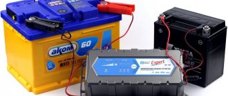
1. DC-DC step-down converter (max. current without additional cooling 6A) Bought here. A good review of this board is here. Price at the time of purchase - 220 rubles. + 70 rub. delivery.
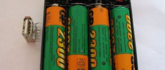
2. Universal tester. I bought it here. Price at the time of purchase - 480 rubles. incl. delivery.
3. Output terminal block. I bought it here. Price at the time of purchase - 80 rubles. + 65 rub. delivery.
4. Diode bridge KVRS1010 (10A). I bought it at a radio parts store. Price at the time of purchase - 60 rubles.
5. Capacitor 50V, 1000 uF. I bought it at a radio parts store. Price at the time of purchase - 25 rubles.
6. Resistors are adjustable. I bought it here. Price at the time of purchase - 110 rubles. + 50 rub. delivery.
The budget for the rework was 1160 rubles.
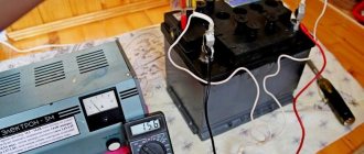
This is what it looked like before modifications.
1. Unsoldered all the wires from the transformer on the secondary winding side and removed the switch. 2. Unscrewed the diodes that were assembled into a diode bridge. I removed them due to the fact that the diodes took up a lot of space and did not allow mounting the converter board and resistors. 3. I removed the front panel and inserted variable resistors, a terminal block and a Tester (monitor) into it. 3 On the aluminum plate on which the diodes were previously located, I mounted a diode bridge and a converter board. I used an empty gel pen refill as bushings. M3 screws are tightly screwed into them. 4. I removed variable resistors from the board to regulate current and voltage. 5. Next, I connected everything in series according to the diagram.
Source
Parameters of a unijunction transistor.
The maximum emitter current for KT117A, KT117B, KT117V, KT117G is 30mA.
The voltage between the bases - for all KT117 - is 30V.
The voltage between base 2 and emitter - for all KT117 - is 30V.
The maximum power dissipation for all KT117s is 300 mW.
Interbase resistance:
For KT117A,B - from 4 to 9 kOhm. For KT117V,G - from 8 to 12 kOhm.
The maximum operating frequency for all KT117s is 200 kHz.
Transfer coefficient - the ratio of the switching voltage to the voltage between the bases: For KT117A - from 0.5 to 0.7 For KT117B - from 0.65 to 0.9 For KT117V - from 0.5 to 0.7 For KT117G - from 0.65 up to 0.9
The transistor housing is plastic or metal-glass. Alphanumeric markings.
Foreign analogues of KT117A (B, V, D) - 2N6027, 2N6028.
Area of use of thyristor devices
For what purposes can a device such as a thyristor power regulator be used? Such a device allows you to more effectively regulate the power of heating devices, that is, load the active places. When working with a highly inductive load, thyristors may simply not close, which can lead to such equipment failing to operate normally.
Is it possible to independently regulate the speed of the device’s engine?
It is worth paying attention to the fact that the regulator cannot independently change its speed in asynchronous motors. Thus, the voltage will be fully regulated on the commutator motor, which is equipped with a special alkaline unit.
Expert opinion
It-Technology, Electrical power and electronics specialist
Ask questions to the “Specialist for modernization of energy generation systems”
Thyristor power regulator, thyristor voltage regulator circuits After the user understands the principle of operation of the device and its general structure, he will be able to understand how to assemble or, if necessary, repair a thyristor power regulator himself. Ask, I'm in touch!
The operating principle of a unijunction transistor.
So, any unijunction transistor contains one pn junction, which is generally clear - from its name.
If there is only one transition, where does it have three electrodes, and how does it even work? On a semiconductor crystal of uniform conductivity, at a certain distance from each other, there are ohmic contacts - Base1(B1) and Base2(B2). Between them there is a pn junction region - a contact with a semiconductor of opposite conductivity, the ohmic contact of which is the emitter. Typically, the operating principle of a unijunction transistor is considered using a simple equivalent circuit.
R1 and R2 here are the resistances between terminals B1 and B2, and V1 is the emitter pn junction. According to this circuit, current will flow through R1 and R2, and the voltage drop across R1 will bias the diode in the opposite direction. Thus, the diode will be closed until a forward voltage greater than the voltage drop across R1 is applied to the emitter. As soon as such voltage is applied, the diode opens and begins to pass current in the forward direction. In this case, the resistance R1 decreases even more - the drop voltage decreases. An avalanche-like process of opening the transistor occurs.
Operating principle and main components
Lead-acid batteries are charged with constant (rectified) voltage, stable in level. To get current flowing into the battery, the charging voltage must be higher than the battery voltage. The charge current in this mode depends on the difference in voltage between the source and the battery.
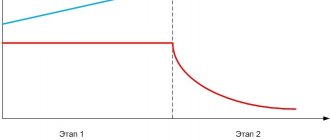
A completely discharged car battery produces a voltage of 10.5 volts (it cannot be discharged below), a fully charged one produces 12.6 volts. During the process, the level at the output of the charger remains constant, and at the battery terminals it gradually increases. Therefore, at the beginning of charging the current will be maximum, at the end - minimum. A decrease in the current level serves as a sign of the end of the process. Also, to automatically complete charging, you can use the voltage on the battery to reach 12.5..12.6 volts.
The process of charging a lead-acid battery with a stable voltage.
The standard charger construction diagram contains:
- Network transformer;
- Rectifier;
- Current (voltage) regulator - stabilized or not.
General scheme for constructing chargers for car batteries.
Instruments that indicate current and voltage are highly desirable. Additionally, the memory can be equipped with:
- current limiting circuit;
- electrical protections;
- indication or automatic shutdown at the end of charging.
These functions are service functions and increase the convenience of working with the memory.
Scheme of a thyristor regulator based on a unijunction transistor.
The figure below shows a diagram of a thyristor regulator, with an incandescent lamp as a load.
R1 - 100 KOhm - variable, 0.5 W, any type. Resistors R2 - 3KOhm, R3 - 1KOhm, R4 - 100 Ohm, R5 - 30KOhm - MLT. VD1 - zener diode D814V VD2 - KD105B VD3 - KD202R VC1 - KU202N Capacitor C1 - 0.1MF 400V, any type. Transistor VT1 - KT117A Fuse 0.5 - 1.5 Ampere (depending on the power of the lamp.)
to Home Page
The use of any materials from this page is permitted provided there is a link to the “Electrical is Easy” website.
Simple charger for car batteries
An easy-to-replicate charger with adjustable charging current using the pulse-phase control method of a thyristor is proposed.
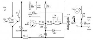
The device diagram is shown in the figure. Setting the required charging current from 0 to 10 A is carried out in a known way: by changing the opening delay of the control element - the SCR - after the moment the alternating supply voltage passes through zero. After connecting the XP1 plug to the network and closing the SA1 switch, a voltage of 220 V, 50 Hz is supplied through the fuse link FU1 to the primary winding of the step-down transformer T1. Capacitor C1 is noise suppressing. Neon lamp HL1 – indicator of the presence of mains voltage. The voltage from the secondary winding, composed of six sections connected in series, is supplied to the diode bridge VD1-VD4 and diodes VD5, VD6. The voltage rectified by the diode bridge is supplied through the ammeter PA1 and the fuse-link FU2 to the positive terminal of the battery being charged, and through the regulating element - the thyristor VS1 to the negative terminal. The rectified voltage from the cathodes of diodes VD5, VD6 and the negative terminal of the bridge VD1-VD4 is supplied to the voltage limiter, and through resistor R2 to the LED HL2. The glow of the latter indicates the presence of voltage on the secondary winding of transformers T1. The limiter is assembled using a zener diode VD7 and resistor R3. From its output, a voltage close to a trapezoidal shape (half-sine wave with cut off vertices) and a frequency of 100 Hz is supplied to the control unit of the trinistor VS1. It is a pulse generator based on a unijunction transistor VT1. Variable resistor R4, resistor R5 and capacitor C2 are the timing circuit of the generator. With the beginning of each trapezoidal pulse, formed, as indicated above, by the zener diode VD7 and resistor R3, charging of capacitor C2 begins through resistors R4, R5. Unijunction transistor VT1 is closed. When capacitor C2 reaches the turn-on voltage of the microcircuit, capacitor C2 is discharged through the circuit section emitter - base 1 of transistor, resistor R6. The pulse on resistor R6 opens the thyristor VS1, and the voltage from the diode bridge VD1-VD4 is supplied to the battery being charged. The duration of this voltage supply is the difference between the duration of the half-cycle of the network voltage (10 ms) and the delay in turning on the SCR from the beginning of the half-cycle (the passage of the network voltage through zero). When the variable resistor R4 slider is moved to the left according to the circuit, the SCR will open closer to the end of each trapezoidal pulse arriving at the control unit, and the charging current will be less. On the contrary, when you move the resistor slider to the right, the charging current will increase.
Structurally, the device can be placed either in a home-made case or in a ready-made one, for example, from some device that has served its useful life. Cases from devices B3-38 - B3-41, B3-47, B3-57 are very suitable, which can be easily modified by replacing the front panel and drilling the required number of ventilation holes to ensure cooling of the device.
Fuse link FU1-VP1-1 5 A, 250 V. It is not recommended to use a link with a lower current, as it will systematically burn out when the device is turned on. Insert FU2 - VP3B for 10 A. Switch SA1 type T3 can be replaced with a key switch with light indication, for example, R59-2 [1], while elements R1 and HL1 are excluded. Capacitor C1 - K73-17 for a voltage of 630 V. Its capacitance can be in the range of 0.01...0.22 µF. This capacitor is soldered directly to terminals 1 and 6 of transformer T1. Capacitor C2 - any with a voltage of at least 25 V.
Transformer T1 is a unified TPP320-127/220-50 [2] with a power of 220 W. It can be replaced with TPP318-127/220-50 or TPP310-127/220-50, the winding connection circuit is identical.
It is possible to use the TPP323-127/220-50 transformer, in which case the windings with pins 11-12, 13-14, 18-17, 20-19 must be connected in parallel, i.e., solder together pins 11, 13, 18, 20 and 12, 14, 17, 19.
The secondary windings of this transformer can be connected in another way by making a rectifier according to the usual full-wave circuit. In this case, instead of the diode bridge VD1-VD4, only two diodes are installed. Windings with terminals 11-12, 13-14 should be connected in parallel, windings with terminals 18-17, 20-19 should also be connected in parallel, i.e. terminals 11, 13 should be together; 12, 14; 14, 17; 19 and 18, 20, and then connect pin 14 to pin 18 - this will be the middle point and the negative terminal of the rectifier. The extreme terminals 11, 13 and 19, 17 are soldered to the anodes of powerful rectifier diodes.
You can also use a network transformer from an old color tube TV. First you need to remove all its secondary windings, while counting the number of turns of the filament winding. Next, on each of the two frames, a new secondary winding is wound with a wire with a cross-section of at least 3 mm2 in any heat-resistant insulation with a number of turns three times greater than incandescent.
After assembling the transformer, the coils are connected in series. If there is no wire of the required cross-section, you can use a bundle of thinner wires, weaving them into a braid [3]. Before installing a homemade transformer, it is necessary to check the insulation resistance between the primary and secondary windings - it must be at least 20 MOhm. Otherwise, you should dry the transformer in a warm, dry place and measure the insulation resistance again, and if it is again less than 20 MOhm, then it is better not to use such a transformer.
D214 diodes can be replaced by any with a forward current of at least 10 A and a reverse voltage of at least 100 V. They are installed on heat sinks with a surface area of at least 50 cm2. Diodes VD5, VD6 – any low-power silicon ones. We can replace the thyristor with any one from the KU202 series or a more powerful one, for example, from the T122 series (T122-20, etc.) [4]. It is installed on a heat sink with an area of at least 100 cm2. We will replace the KT117A transistor with KT117B, KT117G; KT132A, KT132B; KT133A, KT133B or imported 2N2646, 2N2647, 2N4870, 2N4871. Instead of a unijunction transistor, its transistor analogue can be used. Ammeter PA1 and voltmeter PV1 - M4202, M4203. Fixed resistors - any type. Variable resistor R4 with linear characteristic. Its resistance can be from 100 to 680 kOhm. In this case, you will need to select the capacitance of capacitor C2 so that the time constant R4C2 remains the same. The resistor terminals must be connected so that when the handle is rotated clockwise, the introduced resistance decreases.
No printed circuit board was developed. A correctly assembled device does not require adjustment. However, before turning it on for the first time, instead of fuse link FU1, you should connect a 220 V incandescent lamp with a power of 100...150 W. When you turn on SA1, the lamp should flash and go out. If it burns at almost full intensity, you should check the correct connection of the transformer windings and the presence of short circuits in the secondary circuit. Next, turning the variable resistor knob to the extreme counterclockwise (initial) position, connect a 12 V 15 W car lamp in parallel with the voltmeter PV1. It shouldn't glow. By smoothly rotating the variable resistor knob clockwise, you should make sure that the lamp lights up and its brightness increases to full when the voltmeter readings are about 15 V. It may be necessary to adjust the capacitance of capacitor C2. When operating the device, before connecting the load, the handle of the variable resistor R4 should always be set to the initial position.
Literature
- Yushin A. Key switches with light indication. – Radio, 2005, No. 5, p. 52.
- Unified transformers - Radio, 1982, No. 1, p. 59, 60.
- Kobelev F. G. How to make welding machines with your own hands. – Petersburg: Science and Technology, 2011, p. 156.
- Thyristors (Technical reference book). Per. from English, ed. Labuntsova V. A., Obukhova S. P., Sviridova A. F. Ed. 2nd add. – M.: Energy, 1971, p. 111-118.
Authors: A. KVAKINA, P. MIKHEEV, Zheleznogorsk, Krasnoyarsk Territory
Disadvantages of thyristor memory
The simple circuit has a significant disadvantage - the lack of electronic protection against polarity reversal, short circuit and overload. This function is partially performed by a fuse, which is not very convenient. If desired and have sufficient experience, you can assemble an additional protection circuit and connect it separately.
The second drawback is the galvanic connection of the tuning unit with the network. This can be eliminated by using an adjustment resistor with a plastic shaft.
And another disadvantage is the need to install cooling radiators (it is better to use ribbed aluminum products). The problem is partially solved by using a circuit with the inclusion of a control module in winding I of the supply transformer.
To summarize, let’s say that assembling a thyristor charger with your own hands is not as difficult as it might seem at first glance. Perseverance and the time spent will be rewarded with an inexpensive, high-quality charger with smoothly adjustable current, extending the life of the battery.
Schematic and printed circuit board of the SCR memory
The printed circuit board is drawn by hand with a marker. You can make the wiring yourself, for example based on this picture: