The English physicist and chemist Michael Faraday believed that if an electric current can magnetize a piece of iron, then the magnet must also somehow cause the appearance of an electric current. And he was right. In 1831 he discovered the phenomenon of electromagnetic induction.
Definition
Electromagnetic induction is a phenomenon consisting in the occurrence of an electric current in a conducting circuit, which is either at rest in a time-varying magnetic field or moves in a constant magnetic field in such a way that the number of magnetic induction lines penetrating the circuit changes.
Magnetic flux
Before you understand what electromagnetic induction is, you need to define such an entity as magnetic flux.
Imagine that you took a hoop in your hands and went outside into the rain. The heavier the rain, the more water will pass through this hoop— the greater the flow of water .
If the hoop is positioned horizontally, a lot of water will pass through it. And if you start to turn it, it’s already smaller, because it is not located at a right angle to the vertical.
Now let's place the hoop vertically - not a single drop will pass through it (unless the wind blows, of course).
Magnetic flux is essentially the same flow of water through a hoop, only we count the magnitude of the magnetic field passed through the area, not the rain.
Magnetic flux through the area S of the circuit is a scalar physical quantity equal to the product of the magnitude of the magnetic induction vector B, the surface area S penetrated by this flux, and the cosine of the angle α between the direction of the magnetic induction vector and the normal vector (perpendicular to plane of a given surface):
| Magnetic flux Ф - magnetic flux [Wb] B—magnetic induction [T] S - area of the penetrated surface [m^2] n — normal vector (perpendicular to the surface) [-] |
Magnetic flux can be visualized as a value proportional to the number of magnetic lines passing through a given area.
Depending on the angle α, the magnetic flux can be positive (α < 90°) or negative (α > 90°). If α = 90°, then the magnetic flux is 0. This depends on the magnitude of the cosine of the angle.
You can change the magnetic flux by changing the area of the circuit, the field induction module, or the location of the circuit in the magnetic field (by rotating it).
In the case of a non-uniform magnetic field and a non-flat contour, the magnetic flux is found as the sum of the magnetic fluxes penetrating the area of each of the sections into which a given surface can be divided.
MI vector direction
The direction of magnetic fields can be indicated by a magnetic needle placed within the fields. It will spin all the way. The northern end of the arrow will show where B → the unit vector of a particular field is oriented.
Magnetic induction lines
The frame with the current one behaves in exactly the same way, being able to move in the MP without interference. The direction of the induction vector indicates the orientation of the normal to such a closed electromagnetic circuit.
Attention! The gimlet rule (right screw) is used here. If the screw rotates in the same way as the current is directed into the frame, then the forward movement of the screw coincides with the direction of the positive normal.
In some cases, the right-hand rule is used to find direction.
Visual display of MI lines
The line to which a tangent can be drawn, coinciding with point B →, is called the magnetic induction (MI) line. Using such lines, you can visualize the magnetic field. These are closed circuits that block currents. Their density is always proportional to the value of B → at a certain point in the MP.
Information. As for the MF of direct motion of charged particles, these lines are presented in the form of concentric circles. Their center is located in a straight line with the current and in planes located at right angles to it.
The direction of magnetic lines can also be determined using the suspension rule.
Electromagnetic induction
Electromagnetic induction is the phenomenon of the occurrence of current in a closed conducting circuit when the magnetic flux passing through it changes.
The phenomenon of electromagnetic induction was discovered by M. Faraday.
Michael Faraday conducted a series of experiments that helped discover the phenomenon of electromagnetic induction.
Experience once. Two coils were wound on one non-conducting base: the turns of the first coil were located between the turns of the second. The turns of one coil were closed to a galvanometer, and the second was connected to a current source.
When the key was closed and current flowed through the second coil, a current pulse arose in the first. When the switch was opened, a current pulse was also observed, but the current through the galvanometer flowed in the opposite direction.
Experience two. The first coil was connected to a current source, and the second to a galvanometer. In this case, the second coil moved relative to the first. As the coil approached or moved away, the current was recorded.
Experience three. The coil is closed to the galvanometer, and the magnet moves in (extends) relative to the coil
Here's what these experiments showed:
- Induction current occurs only when the lines of magnetic induction change.
- The direction of the current will be different when the number of lines increases and when they decrease.
- The strength of the induction current depends on the rate of change of the magnetic flux. The field itself may change, or the circuit may move in a non-uniform magnetic field.
| Why does induced current occur? Current in a circuit can exist when external forces act on free charges. The work done by these forces to move a single positive charge along a closed loop is equal to the emf. This means that when the number of magnetic lines through the surface limited by the contour changes, an emf appears in it, which is called the induced emf. |
Online physics courses at Skysmart are no less exciting than our articles!
Magnetic field and its graphical representation
Stones that can attract objects made of iron were named after the island on which they were found - magnets. And their property of being located in space in a certain way formed the basis for the creation of a magnetic compass. Understanding how this device works is necessary for further study of the material.
So, the diagram of the simplest magnetic compass is shown in the figure. It consists of a thin needle on which is placed a small diamond-shaped magnet. This magnet can rotate freely on the needle.
As mentioned earlier, in the absence of external influence, magnets are always oriented in space in a certain way: with one end towards the North Pole of the Earth (by analogy, this end of the stone is called the north pole and is indicated in blue); and the other end towards the South (the south pole of the magnet is indicated in red).
Figure 1(a) – Magnetic needle (top view)
Figure 1(b) – Diagram of a simple compass
In 1820, Hans Christian Oersted gave a lecture in which he demonstrated the generation of heat on a current-carrying conductor: he passed current through a long conductor, as a result of which the conductor heated up. During a break between classes, curious students began to turn the installation on and off and accidentally noticed that when current passed through the conductor, a magnetic needle located nearby began to move. The students shared their observation with Oersted, who was very interested in this phenomenon and began to investigate it. The experiments he conducted were later called Oersted's experiments. They became the first evidence of the connection between electric current and magnetic properties.
Consider the experiment conducted by Oersted. A magnetic needle was placed under a long conductor connected to the circuit (see Figure 2).
Figure 2 – Scheme of the experiment of G.Kh. Oersted
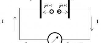
When current begins to flow in the conductor, the magnet rotates to a position perpendicular to the conductor. Its direction depended on where the current was directed. Figure 3 shows a conductor carrying current, the direction of which is indicated by a white arrow. In this case, the magnetic needle was oriented with its blue end to the left.
Figure 3 – Magnetic needle oriented relative to the conductor
If in the installation in Figure 3 the poles of the source are swapped (the current will flow in the opposite direction), the arrow will turn the red end to the left.
That is, the current acts on the needle from the magnet. There is no direct contact between the needle and the conductor (they do not touch each other), which means that the action is carried out using a field*, which was later called magnetic.
It is important to note that the magnetic field:
- affects moving charged particles and substances that have magnetic properties;
- generated by moving charged particles or magnetic substances.
*Reminder: a field is a matter that cannot be seen or felt by the senses, but its effect on some objects can be detected.
Since the field cannot be seen or felt, but must be described and represented, it was decided to depict the magnetic field schematically - in the form of lines.
Magnetic field lines (also known as magnetic lines) are mentally drawn tangential lines towards which magnetic arrows would be oriented (these lines are imaginary; in reality, of course, they do not exist). They are a graphic representation of the magnetic field and are directed in the same direction as the north pole of the magnetic needle.
In Figure 4 you can see the field lines of a rectangular magnet. This type of magnet is often called strip magnet (from the word “strip”).
Figure 4 – Magnetic field lines of a rectangular magnet
Properties of magnetic lines:
- come out from the north pole of the magnet (i.e. start at it);
- enter into the southern one (end on it);
- are either closed or extending to infinity (starting at infinity).
Law of Electromagnetic Induction
The law of electromagnetic induction (Faraday's law) sounds like this:
The induced emf in a closed loop is equal and opposite in sign to the rate of change of the magnetic flux through the surface bounded by the loop.
Mathematically it can be described by the formula:
| Faraday's law Ɛi — induced emf [V] ΔФ/Δt — rate of change of magnetic flux [Wb/s] |
The “–” sign in the formula allows you to take into account the direction of the induction current. The induced current in a closed circuit is always directed so that the magnetic flux of the field created by this current through the surface bounded by the circuit would reduce those changes in the field that caused the appearance of the induced current.
If the circuit consists of N turns (that is, it is a coil), then the induced emf will be calculated as follows.
| Faraday's law for a circuit of N turns Ɛi — induced emf [V] ΔФ/Δt — rate of change of magnetic flux [Wb/s] N - number of turns [-] |
The strength of the induction current in a closed conductive circuit with resistance R:
| Ohm's law for a conductive circuit Ɛi — induced emf [V] I - induction current strength [A] R - circuit resistance [Ohm] |
If a conductor of length l moves with speed v in a constant uniform magnetic field with induction B the emf of electromagnetic induction is equal to:
| Induction emf for a moving conductor Ɛi — induced emf [V] B—magnetic induction [T] v—conductor speed [m/s] l - conductor length [m] |
The occurrence of induced emf in a conductor moving in a magnetic field is explained by the action of the Lorentz force on free charges in moving conductors. The Lorentz force plays the role of an external force in this case.
A conductor moving in a magnetic field through which an induced current flows experiences magnetic braking. The total work done by the Lorentz force is zero.
The amount of heat in the circuit is released either due to the work of an external force, which maintains the speed of the conductor unchanged, or due to a decrease in the kinetic energy of the conductor.
A change in the magnetic flux penetrating a closed circuit can occur for two reasons:
- due to movement of the circuit or its parts in a time-constant magnetic field. This is the case when conductors, and with them free charge carriers, move in a magnetic field
- due to changes in time of the magnetic field with a stationary circuit. In this case, the occurrence of induced emf can no longer be explained by the action of the Lorentz force. The phenomenon of electromagnetic induction in stationary conductors, which occurs when the surrounding magnetic field changes, is also described by Faraday's formula
Thus, the phenomena of induction in moving and stationary conductors proceed in the same way, but the physical reason for the occurrence of induction current turns out to be different in these two cases:
- in the case of moving conductors, the induced emf is due to the Lorentz force
- in the case of stationary conductors, the induced emf is a consequence of the action on free charges of the vortex electric field that occurs when the magnetic field changes.
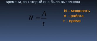
Formula and notation
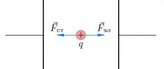
Magnetic induction is denoted by the Latin symbol “B”, and determines the strength of the external influence exerted by the magnetic field on charged particles – in our case, electrons, denoted “q” – at a certain point. The speed of movement of charged particles is denoted by the letter “U”.
The physical formula of magnetic induction itself is as follows:
We also recommend reading: Interesting facts about Karamzin
Where:
- Fmach is the greatest force acting on the conductor.
- L is its length.
- I is the current strength of charged particles in the metal.
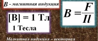
The unit of induction in the international SI system is “tesla”, abbreviated in the Russian version as “Tl”, in the international version as “T”. This name is given in honor of the Serbian scientist N. Tesla. In the old CGS metric system, the unit of induction was designated "Gauss" after the German physicist. GS – among Russian-speaking scientists, and G – in the international version.
If your bank card is demagnetized – what to do?
Lenz's rule
To determine the direction of the induced current, you need to use Lenz's rule.
Academically, this rule is as follows: the induced current excited in a closed loop when the magnetic flux changes is always directed in such a way that the magnetic field it creates prevents the change in the magnetic flux causing the induced current.
Let's try a little simpler: the coil in this case is a dissatisfied granny. They take away her magnetic flux - she is unhappy and creates a magnetic field, which this magnetic flux wants to take back.
They give her a magnetic flux, take it, they say, use it, and she’s like, “Why did I give up your magnetic flux!” and creates a magnetic field, which expels this magnetic flux.
Inhomogeneous and homogeneous magnetic field
If we return to the research of G.Kh. Oersted and observe the behavior of the arrow at various points, you can notice that the further the arrow is removed from the conductor, the less it deviates. This means that the field weakens with distance from the source.
What the magnetic field lines of a current-carrying conductor look like is shown in Figure 5. The reader is presented with a cross-section of a conductor with current flowing “into the drawing.” In this case, the field lines are concentric circles. Where the field is more intense (close to the source - conductor) the lines are drawn thicker, and in areas where it is weaker - less often.
Figure 5 – Magnetic field lines of a current-carrying conductor
A field that acts on a magnetic needle with the same force at different points in space is called uniform.
In the opposite situation, they speak of a non-uniform magnetic field.
Strictly speaking, the magnetic field is almost always inhomogeneous. Nevertheless, the field created by some sources can be considered homogeneous in some small area. For example, the field in the area between magnets located in series (see Figure 6). The induction lines of a uniform magnetic field are parallel, and the density with which they are depicted does not change.
Figure 6 – Field between two magnets in series