Three-phase asynchronous motor: what to pay attention to before connecting it
With a few exceptions, we get the asynchronous machine in an unknown state. Very rarely does it have an inspection certificate and a certified warranty from an electrical laboratory.
Even in this case, I recommend making sure it works personally.
Mechanical condition of the stator and rotor: what can interfere with engine operation
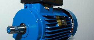
The fixed stator consists of three parts: a middle housing and two side covers, secured with studs. Pay attention to the gap between them and the tightening force with the nuts.
The body must be tightly compressed. A rotor rotates inside it on bearings. Try turning it by hand. Evaluate the force applied: how the bearings work, whether there are any beats.
Without proper experience, minor defects cannot be detected in this way, but a case of severe jamming will immediately appear. Listen to the noises: is there any contact with the stator elements by the rotor when rotating?
After turning the engine to idle and running for a short time, listen again to the sounds of rotating parts.
Ideally, it is better to disassemble the stator, visually assess its condition, wash the dirty rotor bearings and completely replace their lubricant.
Electrical characteristics of stator windings: how to check the assembly circuit
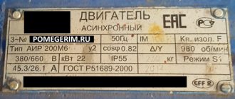
The manufacturer indicates all the main parameters of the electric motor on a special plate attached to the stator housing.
You can trust these factory specifications only if you are sure that after the factory, none of the electricians changed the winding connection diagram or made involuntary mistakes. And I came across such cases.
And the sign itself may become erased or lost over time. Therefore, I propose to understand the technology of rotor spin-up.
To understand the electrical processes occurring inside the motor stator, it is convenient to imagine it in the form of an ordinary toroidal transformer, when three equal windings are symmetrically located on the ring core of the magnetic circuit.
The stator circuit is assembled inside a closed housing, from which only six ends of the windings are removed.
They are marked and connected on a terminal block covered with a lid for assembly according to a star or delta circuit using a standard rearrangement of jumpers.
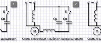
The right side of the picture shows the assembly of the triangle. I publish the jumper arrangement diagram for the star below.
Electrical methods for checking winding assembly circuits
But not everything is as simple as it might seem at first glance. There are a number of engines that deviate from these rules.
For example, a manufacturer may produce electric motors not for universal use, but for operation in specific conditions with the windings connected in a star configuration.
In this case, he can assemble the three ends of the windings inside the stator housing, and bring out only four wires for connection to the phase and zero potentials.
Installation of these ends is usually performed in the area of the back cover. To switch the windings to a triangle, you will need to open the housing and make additional conclusions.
It's not a difficult job. But it requires careful handling of the varnish coating of the copper wire. When the wire is bent, it may be damaged, which will lead to a breakdown of the insulation and create an interturn short circuit.
After rewiring the circuit, I recommend additionally coating the outer layers of the windings with varnish, and then drying them thoroughly with warm air before final assembly.
What to do if there are no pin markings
On an old asynchronous motor, the wires may be removed from the terminals, and the factory markings may be lost. There were also instances where six ends simply stuck out from the body. They need to be called and labeled.
We carry out the work in two stages:
- We check that the ends belong to the windings.
- We identify and label each pin.
At the first stage, we use a multimeter or tester in ohmmeter mode. We place the first probe randomly on one terminal, and with the second, we look for the one from the five remaining wires where the device will show a shorted circuit. We mark both ends as belonging to the same winding.
We proceed in the same way with the remaining four conclusions. As a result, we get three pairs of wires from each winding.
How to find the end and beginning of a winding: 2 ways
You can search using a voltmeter:
- and batteries;
- or a reduced AC voltage source.
The first method is based on the fact that a current pulse applied to one of the three windings is transformed into the other two.
To do this, connect the negative battery to a randomly selected end of K1, and briefly touch the second terminal with the positive contact. A pulsed inrush current passes through the circuit and induces an EMF in the other two windings.
Using a DC voltmeter, the polarity of the induced voltage in each winding is checked by the deflection of the arrow. The beginning is marked with the terminal that corresponds to the positive potential (the arrow of the device moves to the right when the battery is closed and to the left when the circuit is opened by the battery).
After marking the ends, I recommend checking the correctness of their application by applying a pulse to another winding.
The second method is based on the use of an alternating voltage source of a safe value of 12-36 volts.
The ends of any two windings are connected in parallel and a voltmeter is connected to them. An alternating voltage is applied to the remaining third winding and the reading of the device is looked at.
If the induced EMF corresponds to the applied voltage, then these two windings are connected in the same polarity. Their beginnings and ends are marked equally. If the voltmeter reading is zero, the ends of one of the windings must be unscrewed and the measurement taken again.
Then one of the marked windings, for example No. 3, is connected to the first and a voltmeter is connected to them. The vacated No. 2 is again supplied with alternating voltage. The polarity of the terminals is determined by the magnitude of the EMF on the voltmeter.
After marking is completed, a control measurement is taken to check the work performed.
When there is no step-down transformer or safe power supply at hand, an experienced electrician with the right to independently work under voltage can use an ordinary 60-watt incandescent lamp.
It is used as a voltage divider, connected in series to one winding of the electric motor. 220 volts are supplied to the assembled chain, and the voltage is measured on the other two with a voltmeter.
This kind of testing is dangerous. This should not be done by untrained people: you can easily get an electrical injury.
How to assess the condition of winding insulation
Some bloggers are silent about the need for this check. They believe that they can do without it in most cases.
However, before energizing the engine, I recommend:
- take a megohmmeter with an output voltage of 1000 volts;
- check the insulation between each individual winding and the housing, as well as between all windings;
- if it is higher than 0.5 MΩ, then consider the starter to be in good condition. Otherwise you will have to repair it. Drying with dry and warm air often helps.
Checking the insulation of the electric motor with a megohmmeter must be carried out before connecting it to load. However, it is not able to detect damage to the dielectric layer that causes interturn short circuits in the winding.
When assembling the engine, each stator coil is wound with copper wire of the same length and cross-section. Therefore, they all have exactly the same resistive resistance.
If an interturn short circuit occurs in the winding, then, as a rule, it can be determined by measuring a multimeter in ohmmeter mode. To do this, carefully analyze and compare the active resistance of each chain.
How to check the stator magnetic field at the factory
When voltage is applied to a working electric motor, a rotating magnetic field is created. It is visually assessed using a metal ball that repeats the rotation.
I do not encourage you to repeat such an experience. This example is intended to help you understand that the operation of an asynchronous motor is based on the interaction of the magnetic fields of the stator and rotor.
Only the correct connection of the windings ensures the rotation of the ball or rotor.
Motor power and winding wire diameter
These are two interrelated quantities because the cross-section of the conductor is selected based on its ability to withstand heating from the current flowing through it.
The thicker the wire, the more power can be transmitted through it with acceptable heating.
If there is no plate on the engine, then its power can be judged by two signs:
- The diameter of the winding wire.
- Dimensions of the magnetic core.
After opening the stator cover, analyze them visually.
Connecting a three-phase motor to a single-phase network according to a star circuit
Let me start with a warning: even experienced electricians make mistakes during work, which are called “human factor”. What can we say about home craftsmen...
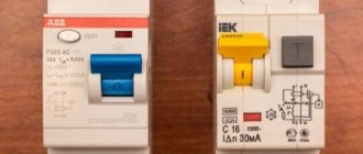
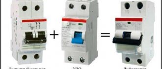
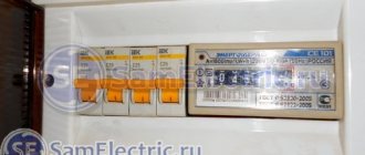
Therefore, I recommend that voltage be supplied to the assembled circuit only through a separate SF circuit breaker, correctly selected for the load. It will save life and health.
The star connection diagram is shown in the picture.
The ends of the windings are collected at one point by horizontal jumpers inside the terminal box. There are no external wires connected to it.
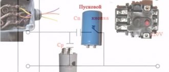
Phase (via a circuit breaker) and neutral of household wiring are supplied to two different terminals of the beginning of the windings. A parallel chain of two capacitors is connected to the free terminal (H2 in Figure): Cp - working, Sp - starting.
The working capacitor is connected by a second plate rigidly to the phase wire, and the starting capacitor is connected through an additional switch SA.
When starting the electric motor, the rotor must be spun from rest. It overcomes the frictional forces of bearings and environmental resistance. For this period, it is necessary to increase the magnitude of the stator magnetic flux.
This is done by increasing the current through an additional circuit of the starting capacitor. After the rotor reaches operating mode, it must be turned off. Otherwise, the starting current will overheat the motor winding.
It is not always convenient to disable the starting chain with a simple switch. To automate this process, circuits with relays or time-based starters are used.
The start button from Soviet activator-type washing machines is popular among DIYers. It has two built-in contacts, one of which, after switching on, turns off automatically with a delay: what is needed in our case.
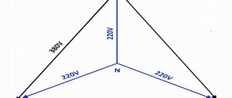
If you look closely at the principle of supplying single-phase voltage, you will see that 220 volts are applied to two windings connected in series. Their total electrical resistance adds up, weakening the amount of current flowing.
Connecting a three-phase motor to a single-phase network according to a star circuit is used for low-power devices and is characterized by increased energy losses of up to 50% of a three-phase power system.
What can be redone
Low-power 380 Volt electric motors are suitable for conversion: up to 3 kW. Theoretically, powerful motors are also reconnected. But this will additionally entail the installation of a separate circuit breaker in the electrical panel and special wiring. And this work becomes meaningless if it suddenly turns out that the input cable cannot carry such a load.
Even if your network carries high loads, and you managed to convert a 3 kW motor from 380 to 220 Volts, you will be upset the first time you put it into operation. The launch will be difficult. You will decide that the work was in vain. Therefore, if you redo it, then it will be low-power models.
Triangle scheme: advantages and disadvantages
Connecting an electric motor using this method involves using the same external circuit as the star. The phase, zero and midpoint of the lower plates of the capacitors are mounted in series on three jumpers of the terminal box.
By switching the winding terminals in a delta pattern, the applied voltage 220 creates more current in each winding than the star. There are lower energy losses and higher efficiency.
Connecting the motor according to a delta circuit in a single-phase network allows you to usefully use up to 70-80% of the power consumption.
To form a phase-shifting chain, it is necessary to use a smaller capacity of working and starting capacitors.
When you turn on the engine, it may begin to rotate in the wrong direction. We need to reverse it.
To do this, in both circuits (star or triangle) it is enough to swap the wires coming from the network on the terminal block. The current will flow through the winding in the opposite direction. The rotor will change direction of rotation.
Reconnection from 380 volts to 220
It is very important to understand how a three-phase electric motor is connected to a 220V network. To connect a three-phase motor to 220V, note that it has six terminals, which corresponds to three windings. Using a tester, the wires are pinged to find the coils. We connect their ends in twos - we get a “triangle” connection (and three ends).
To begin with, we connect the two ends of the network wire (220 V) to any two ends of our “triangle”. The remaining end (the remaining pair of twisted coil wires) is connected to the end of the capacitor, and the remaining capacitor wire is also connected to one of the ends of the power wire and coils.
Whether we choose one or the other will depend on which direction the engine starts to rotate. Having completed all the above steps, we start the engine by applying 220 V to it.
The electric motor should work. If this does not happen, or it does not reach the required power, you need to return to the first stage to swap the wires, i.e. reconnect the windings.
If, when turned on, the motor hums but does not spin, you need to additionally install (via a button) a capacitor. At the moment of starting, it will give the engine a push, forcing it to spin.
Video: How to connect an electric motor from 380 to 220
Calling, i.e. resistance measurement is carried out by a tester. If this is not available, you can use a battery and a regular flashlight lamp: the identified wires are connected to the circuit in series with the lamp. If the ends of one winding are found, the lamp lights up.
It is much more difficult to determine the beginning and ends of the windings. You can't do without a voltmeter with an arrow.
You will need to connect a battery to the winding, and a voltmeter to the other.
By breaking the contact of the wire with the battery, observe whether the arrow deviates and in which direction. The same actions are carried out with the remaining windings, changing the polarity if necessary. Make sure that the arrow deviates in the same direction as during the first measurement.
How to choose capacitors: 3 important criteria
A three-phase motor creates a rotating magnetic field of the stator due to the uniform passage of sinusoidal currents through each winding, spaced apart in space by 120 degrees.
There is no such possibility in a single-phase network. If you connect one voltage to all 3 windings at once, there will be no rotation - the magnetic fields will balance. Therefore, voltage is applied to one part of the circuit as it is, and the current is shifted to the other according to the angle of rotation by capacitors.
The addition of two magnetic fields creates an impulse of moments that spin the rotor.
The performance of the created circuit depends on the characteristics of the capacitors (capacitance value and permissible voltage).
For low-power engines with easy starting at idle, in some cases it is permissible to use only working capacitors. All other engines will require a starting block.
I draw attention to three important parameters:
- capacity;
- permissible operating voltage;
- type of construction.
How to choose capacitors by capacitance and voltage
There are empirical formulas that allow you to perform a simple calculation based on the rated current and voltage.
However, people often get confused about the formulas. Therefore, when checking the calculation, I recommend taking into account that for a power of 1 kilowatt it is necessary to select a capacitance of 70 microfarads for the operating circuit. The dependence is linear. Feel free to use it.
All these methods can and should be trusted, but theoretical calculations must be tested in practice. The specific design of the engine and the loads applied to it always require adjustments.
Capacitors are designed for the maximum current value allowed under the heating conditions of the wire. This consumes a lot of electricity.
If the electric motor overcomes loads of smaller magnitude, then it is advisable to reduce the capacitance of the capacitors. This is done experimentally during setup, measuring and comparing the currents in each phase with an ammeter.
Most often, metal-paper capacitors are used to start an asynchronous electric motor.
They work well but have low ratings. When assembled into a capacitor bank, the result is a rather large design, which is not always convenient even for a stationary machine.
Nowadays the industry produces small-sized electrolytic capacitors adapted for operation with alternating current electric motors.
Their internal structure of insulating materials is adapted to work under different voltages. For a working chain it is at least 450 volts.
For a starting circuit with conditions of short-term switching on under load, it is reduced to 330 due to a decrease in the thickness of the dielectric layer. These capacitors are smaller in size.
This important condition must be well understood and put into practice. Otherwise, 330 volt capacitors will explode during prolonged operation.
Most likely, for a particular engine, you won’t be able to get rid of it with just a capacitor. You will need to assemble the battery using a series and parallel connection of them.
When connected in parallel, the total capacitance is summed, but the voltage does not change.
Connecting capacitors in series reduces the total capacitance and divides the applied voltage between them.
What types of capacitors can be used
The rated voltage of the network is 220 volts - this is the effective value. Its amplitude value is 310 volts. Therefore, the minimum limit for short-term operation at startup is 330 V.
A voltage reserve of up to 450 V for working capacitors takes into account surges and impulses that are created in the network. It cannot be underestimated, and the use of capacities with a large reserve significantly increases the dimensions of the battery, which is irrational.
For a phase-shifting chain, it is permissible to use polar electrolytic capacitors, which are designed to allow current to flow in only one direction. Their connection circuit must contain a current-limiting resistor of several ohms.
Without its use, they quickly fail.
Before installing any capacitor, you should check its actual capacity with a multimeter, and not rely on the factory markings. This is especially true for electrolytes: they often dry out prematurely.
Using a magnetic starter
The good thing about using a 380 electric motor connection diagram is that it can be started remotely. The advantage of a starter over a switch (or other device) is that the starter can be placed in a cabinet, and the controls can be placed in the work area; the voltage and currents are minimal, therefore, the wires are suitable for a smaller cross-section.
In addition, connection using a starter ensures safety in the event that the voltage “disappears,” since this opens the power contacts, and when the voltage appears again, the starter will not supply it to the equipment without pressing the start button.
Connection diagram for a 380V electric asynchronous motor starter:
At contacts 1,2,3 and start button 1 (open), voltage is present at the initial moment. Then it is supplied through the closed contacts of this button (when you press “Start”) to the contacts of the coil starter K2, closing it. The coil creates a magnetic field, the core is attracted, the contacts of the starter close, driving the motor.
At the same time, the NO contact closes, from which the phase is supplied to the coil through the “Stop” button. It turns out that when the “Start” button is released, the coil circuit remains closed, as do the power contacts.
By pressing “Stop”, the circuit is broken, returning the power contacts to open. The voltage disappears from the conductors and NO supplying the engine.
Video: Connecting an asynchronous motor. Determination of engine type.
If you have a three-phase electric motor, you know it doesn't come cheap. Therefore, if you need to use a single-phase motor, the thought of buying new equipment will only come to you when you do not know how to make an electric motor at home. We will tell you how to convert an electric motor from 380 to 220 Volts with your own hands.
Diagram of phase shift of currents with capacitors and a choke: what I didn’t like
This is the third design promised in the title, which I implemented two decades ago, tested it in operation, and then abandoned it. It allows you to use up to 90% of the three-phase motor power, but has disadvantages. More on them later.
I assembled a three-phase voltage converter with a power of 1 kilowatt.
It includes:
- 140 Ohm inductive reactance choke;
- capacitor bank for 80 and 40 microfarads;
- adjustable rheostat 140 Ohm with a power of 1000 watts.
One phase works in the usual way. The second with a capacitor shifts the current forward by 90 degrees along the rotation of the electromagnetic field, and the third with a choke forms its lag by the same angle.
The currents of all three stator phases participate in the creation of a phase-shifting magnetic moment.
The throttle body had to be assembled using a mechanical structure made of wood on springs with a threaded air gap adjustment to adjust its characteristics.
The design of the rheostat is generally “tinny”. Now it can be assembled from powerful resistors purchased in China.
I even thought about using a water rheostat.
But I refused it: the design was too dangerous. I simply wound a thick steel wire around an asbestos pipe for the experiment and laid it on the bricks.
When I started the circular saw engine, it worked normally, withstood the applied loads, and sawed fairly thick blocks normally.
Everything would be fine, but the meter wound up at double the rate: this converter takes on the same power as the engine. The choke and wire heated up quite well.
Due to high power consumption, low safety, complex design, I do not recommend this converter.