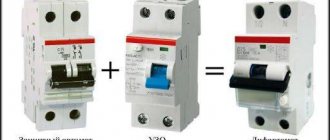
Selecting a starting capacitor for an electric motor
A modern approach to this issue involves the use of special calculators on the Internet that perform quick and accurate calculations.
To carry out the calculation, you should know and enter the following indicators:
- Motor winding connection type: delta or star. The capacitance also depends on the type of connection.
- Engine power is one of the determining factors. This indicator is measured in Watts.
- Mains voltage is taken into account in calculations. As a rule, it can be 220 or 380 Volts.
- Power factor is a constant value that is often 0.9. However, it is possible to change this indicator during calculation.
- The efficiency of the electric motor also affects the calculations performed. This information, as well as others, can be found by studying the information printed by the manufacturer. If it is not there, you should enter the engine model on the Internet to search for information about what the efficiency is. You can also enter an approximate value, which is typical for such models. It is worth remembering that efficiency may vary depending on the condition of the electric motor.
Such information is entered into the appropriate fields and an automatic calculation is carried out. At the same time, we obtain the capacity of the working condensate, and the starting condensate should have an indicator 2.5 times greater.
You can carry out such a calculation yourself.
To do this, you can use the following formulas:
- For the star winding connection type, the capacitance is determined using the following formula: Cр=2800*I/U. In the case of a triangle connection of the windings, the formula Cр=4800*I/U is used. As you can see from the information above, the type of connection is the determining factor.
- The above formulas determine the need to calculate the amount of current that passes through the system. For this, the formula is used: I=P/1.73Uηcosφ. For the calculation you will need engine performance indicators.
- After calculating the current, you can find the capacitance indicator of the working capacitor.
- The starting one, as previously noted, should be 2 or 3 times higher in capacity than the working one.
When choosing, you should also consider the following nuances:
- Operating temperature range.
- Possible deviation from the calculated capacity.
- Insulation resistance.
- Loss tangent.
Usually, the above parameters are not paid much attention. However, they can be taken into account to create an ideal electric motor power system.
Overall dimensions can also be a determining factor. In this case, the following dependence can be distinguished:
- Increasing the capacitance leads to an increase in the diametrical size and outlet distance.
- The most common maximum diameter is 50 millimeters with a capacitance of 400 µF. At the same time, the height is 100 millimeters.
In addition, it is worth considering that on the market you can find models from foreign and domestic manufacturers. As a rule, foreign ones are more expensive, but also more reliable. Russian versions are also often used when creating an electric motor connection network.
Why adjustment is needed
The calculation method given above is approximate. Firstly, the nominal value indicated on the body of the electrical capacitance may differ significantly from the actual one. Secondly, paper capacitors (generally speaking, an expensive thing) are often second-hand, and they, like any other items, are subject to aging, which leads to an even greater deviation from the specified parameter. Thirdly, the current that will be consumed by the motor depends on the magnitude of the mechanical load on the shaft, and therefore it can only be assessed experimentally. How to do it?
This requires a little patience. The result can be a fairly large set of capacitors connected in parallel and in series. The main thing is to secure everything well after finishing the work so that the soldered ends do not fall off due to vibrations emanating from the motor. And then it would be a good idea to analyze the result again and, possibly, simplify the design.
Asynchronous or collector: how to distinguish
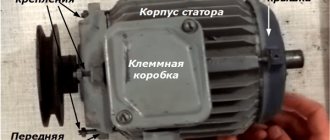
In general, you can distinguish the type of engine by a plate - a nameplate - on which its data and type are written. But this is only if it has not been repaired. After all, anything can be under the casing. So if you are not sure, it is better to determine the type yourself.
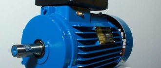
This is what a new single-phase capacitor motor looks like
How do collector motors work?
You can distinguish between asynchronous and commutator motors by their structure. The collectors must have brushes. They are located near the collector. Another mandatory attribute of this type of engine is the presence of a copper drum, divided into sections.
Such motors are produced only as single-phase ones; they are often installed in household appliances, as they allow one to obtain a large number of revolutions at the start and after acceleration. They are also convenient because they easily allow you to change the direction of rotation - you just need to change the polarity. It is also easy to organize a change in the rotation speed by changing the amplitude of the supply voltage or its cutoff angle. That is why such engines are used in most household and construction equipment.
Commutator motor structure
The disadvantages of commutator motors are high operating noise at high speeds. Remember a drill, an angle grinder, a vacuum cleaner, a washing machine, etc. The noise during their operation is decent. At low speeds, commutator motors are not so noisy (washing machine), but not all tools operate in this mode.
The second unpleasant point is that the presence of brushes and constant friction leads to the need for regular maintenance. If the current collector is not cleaned, contamination with graphite (from brushes being worn out) can cause adjacent sections in the drum to become connected and the motor simply stops working.
Asynchronous
An asynchronous motor has a stator and a rotor, and can be single or three-phase. In this article we consider connecting single-phase motors, so we will only talk about them.
Asynchronous motors are characterized by a low noise level during operation, therefore they are installed in equipment whose operating noise is critical. These are air conditioners, split systems, refrigerators.
Structure of an asynchronous motor
There are two types of single-phase asynchronous motors - bifilar (with a starting winding) and capacitor. The whole difference is that in bifilar single-phase motors the starting winding works only until the motor accelerates. Afterwards it is turned off by a special device - a centrifugal switch or a start-up relay (in refrigerators). This is necessary, since after overclocking it only reduces efficiency.
In capacitor single-phase motors, the capacitor winding runs all the time. Two windings - main and auxiliary - are shifted relative to each other by 90°. Thanks to this, you can change the direction of rotation. The capacitor on such engines is usually attached to the housing and is easy to identify by this feature.
You can more accurately determine the bifilar or capacitor motor in front of you by measuring the winding resistance. If the resistance of the auxiliary winding is twice as large (the difference can be even greater), most likely this is a bifilar motor and this auxiliary winding is a starting winding, which means that a switch or starting relay must be present in the circuit. In capacitor motors, both windings are constantly in operation and connecting a single-phase motor is possible through a regular button, toggle switch, or automatic machine.
Single phase
In order to connect a single-phase asynchronous motor, two buttons are enough: one with a latch, the other without it. Standard circuit: two windings connected in series (although there may be variations depending on the model). The one with greater resistance is the starting one, the other is the working one.
Each model of electric machine has its own characteristics, which means the connection options may vary. Some use two capacitors to start, others use one.
Therefore, you need to start by finding out the model and its technical characteristics.
As you can see, starting short-circuited electric machines is possible in different ways. Connection is possible both at home and at work, which is what made them so popular. And, by and large, nothing better has been invented in more than a hundred years.
How to calculate the capacity of a working capacitor
For two connections of windings, slightly different ratios are taken.
The formula introduces the connection coefficient Kc, which for a triangle is 4800, and for a star - 2800.
Cр=Кс*I/U;
I=P/(√3*U*η*cosϕ);
or
Cр=Кс*P/(√3*U²*η*cosϕ).
Where the values of P (power), U (voltage 220 V), η (motor efficiency, as a percentage divided by 100) and cosϕ (power factor) are taken from the motor nameplate.
You can calculate the value using a regular calculator or using something like a similar calculation table. In it you need to substitute the values of the engine parameters (yellow fields), the result is obtained in the green fields in microfarads
Table
However, there is not always confidence that the engine operating parameters correspond to what is written on the nameplate. In this case, you need to measure the real current with a measuring clamp and use the formula Cр = Кс*I/U.
Calculation of the total capacity
When capacitors are connected in parallel, their capacitances add up, but when they are connected in series, on the contrary, the total capacitance will be less, here the sum of the reciprocal values is equal. When two identical capacitors are connected in parallel, the total capacitance doubles, and if in series, it is halved. That is, the sum of the capacitance of two 100 microfarad capacitors can be either 200 μF or 50 μF. It all depends on the type of connection between them.
Another example: the total capacitance of capacitors of 60 μF and 90 μF with a parallel connection will be 150 μF, with a series connection - 36 μF. This can be used creatively when choosing from what you have or buying cheaper.
Model overview
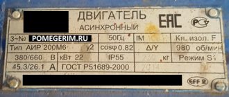
electric motor AIR
One of the most popular are electric motors of the AIR series. There are models made on feet 1081, and models of combined design - feet + flange 2081.
Electric motors in the foot + flange design will cost about 5% more than similar ones with feet.
As a rule, manufacturers provide a warranty of 12 months.
For electric motors with a rotation height of 56-80 mm, the frame is made of aluminum. Motors with a rotation height of more than 90 mm are available in cast iron.
Models differ in power, rotation speed, height of the rotation axis, and efficiency.
The more powerful the engine, the higher its cost:
- An engine with a power of 0.18 kW can be purchased for 3 thousand rubles (electric motor AIRE 56 B2).
- A model with a power of 3 kW will cost about 10 thousand rubles (AIRE 90 LB2).
As for the rotation speed, the most common models are with frequencies of 1500 and 3000 rpm, although there are engines with other frequency values. With equal power, the cost of an engine with a speed of 1500 rpm is slightly higher than that of one with a speed of 3000 rpm.
The height of the rotation axis for motors with 1 phase varies from 56 mm to 90 mm and directly depends on the power: the more powerful the engine, the greater the height of the rotation axis, and therefore the price.
Different models have different efficiencies, typically ranging from 67% to 75%. Greater efficiency corresponds to a higher cost of the model.
You should also pay attention to engines produced by the Italian company AACO, founded in 1982:
- Thus, the AACO series 53 electric motor is designed specifically for use in gas burners. These motors can also be used in washing installations, warm air generators, and central heating systems.
- Electric motors of the 60, 63, 71 series are designed for use in water supply installations. Also, the company offers universal motors of the 110 and 110 compact series, which are distinguished by a diverse range of applications: burners, fans, pumps, lifting devices and other equipment.
Selecting a capacitor
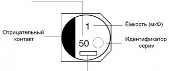
In an alternating current circuit - and this is exactly our case - you should not use polar capacitors that have positive and negative contacts (anode and cathode). But if necessary, this problem can be circumvented by using a diode bridge or two polar capacitors combined into one by connecting contacts of the same name, but here again it is better to call an experienced electrician.
There is a formula for the required capacity of a working capacitor, but having calculated it, you will still need to check the operation of the device in practice. If there are any capacitors, it is better to immediately switch to the method of thoughtful selection, but thoughtful, and not completely thoughtless. Capacitors must be non-polar, have the same operating voltage, no less than 300 V, but preferably 400 V and higher.
The operating voltage of the capacitors must be the SAME, otherwise the one where it is lower will fail.
Start with a value of 30 microfarads (μF) per 1 kilowatt of rated motor power when connecting the stator windings with a star; with a triangle, you can try with 50−70 μF. The electric motor at idle speed (without load) should start and gain speed without getting too hot; prolonged idling is undesirable, the engine may burn out. If the idle start occurs normally, without overheating and a burning smell, then the working capacitor has been selected and will work on it, connect the load and continue testing in working condition.
What if the connection of a 380 V electric motor to 220 V through a capacitor occurs immediately under a serious load? Here you will need a starting capacitor; its capacitance must begin to be selected from values one and a half times greater than the working one. Example: working 60 μF, then the starting one is initially set to 90 μF and, if there is no normal starting, then we add the capacitance of the starting circuit of capacitors (the approximate capacity of the starting circuit is up to three working ones, in our example up to 180 μF). After reaching operating speed, the starting capacitors are turned off, leaving only the working one. The circuits of the working and starting capacitors are parallel; a separate switch can be placed in each.
In a household network, you do not need to use devices with a power of more than 3 kW - the protection will work or the wiring will burn out.
Starting a 3-phase motor from 220 Volts
Starting a 3-phase motor from 220 Volts
Often there is a need to connect a three-phase electric motor in a subsidiary farm, but there is only a single-phase network (220 V). Nothing, the matter can be fixed. You just have to connect a capacitor to the motor and it will work.
Read more in detail below
The capacity of the capacitor used depends on the power of the electric motor and is calculated by the formula
C = 66·Рnom,
where C is the capacitance of the capacitor, μF, Rnom is the rated power of the electric motor, kW.
That is, we can assume that for every 100 W of power of a three-phase electric motor, about 7 μF of electrical capacitance is required.
For example, a 600 W electric motor requires a capacitor with a capacity of 42 μF. A capacitor of such a capacity can be assembled from several parallel-connected capacitors of smaller capacity:
So, the total capacitance of the capacitors for a 600 W motor must be at least 42 μF. It must be remembered that capacitors are suitable whose operating voltage is 1.5 times the voltage in a single-phase network.
Capacitors of the KBG, MBGCh, and BGT types can be used as working capacitors. In the absence of such capacitors, electrolytic capacitors are also used. In this case, the housings of the electrolytic capacitors are connected to each other and are well insulated.
Note that the rotational speed of a three-phase electric motor operating from a single-phase network almost does not change compared to the rotational speed of the motor in three-phase mode.
Most three-phase electric motors are connected to a single-phase network in a delta circuit (Fig. 1). The power developed by a three-phase electric motor connected in a delta circuit is 70-75% of its rated power.
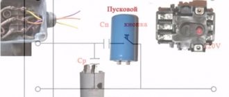
A three-phase electric motor is also connected according to the “star” circuit (Fig. 2).
To make a star connection, you need to connect two phase windings of the electric motor directly to a single-phase network (220 V), and the third through a working capacitor (Cp) to any of the two network wires.
To start a three-phase electric motor of low power, usually only a running capacitor is sufficient, but with a power greater than 1.5 kW, the electric motor either does not start or picks up speed very slowly, so it is also necessary to use a starting capacitor (Cn). The capacity of the starting capacitor is 2.5-3 times greater than the capacity of the working capacitor. Electrolytic capacitors of the EP type or the same type as the working capacitors are best used as starting capacitors.
The connection diagram for a three-phase electric motor with a starting capacitor Sp is shown in Fig. 3.
Final conclusions
- Existing technical methods make it possible to connect three-phase asynchronous motors to a single-phase 220 volt network. Numerous researchers offer a wide range of experimental schemes for this purpose.
- However, this method does not ensure efficient use of electrical power resources due to large energy losses associated with poor-quality voltage conversion for connection to the stator phases. Therefore, the engine operates with low efficiency and increased costs.
- Long-term operation of machines with such engines is not economically justified.
- The method can only be recommended for connecting non-critical mechanisms for a short period of time.
- In order to effectively use an asynchronous electric motor, it is necessary to use a full three-phase connection or a modern, expensive inverter converter of appropriate power.
- A single-phase electric motor with the same power in a household network is better able to cope with all tasks, and its operation will be cheaper.
Thus, the designs of asynchronous motors, previously widely connected to home wiring, are now not popular, and the method of connecting them is outdated and rarely used.
A variant of such a mechanism is shown in a photograph of an emery board with the protective shield and limit stop removed for clarity. Even with this design, it is difficult to work on it due to power losses.
Practical advice from Alexander Shenrok, presented in his video, clearly complements the material in the article and allows you to better understand this topic. I recommend viewing it, but be critical of measuring the insulation resistance with a tester.
Ask questions in the comments, share the article with friends via social network buttons.
Design and purpose of capacitors
This element of the electrical circuit consists of two plates (plates). The plates are positioned relative to each other so that there is a gap between them. When a capacitor is connected to an electric current circuit, charges accumulate on the plates. Due to the physical gap between the plates, the device has low conductivity.
Attention! This gap can be air or filled with a dielectric. The following dielectrics are used: paper, electrolyte, oxide films. The main feature of such a two-terminal network is the ability to accumulate electric field energy and instantly transfer it to the load (charge and discharge)
The main feature of such a two-terminal network is the ability to accumulate electric field energy and instantly transfer it to the load (charge and discharge).
Part device
The first prototype of the container was the Leyden jar, created in 1745 in the city of Leiden by the German von Kleist. The jar was lined with copper foil inside and out. This is how the idea of creating covers came about.
Leyden jars connected in parallel
The graphic designation of a two-terminal network on diagrams and drawings is two vertically located lines (like plates) with a gap between them.
Designation on diagrams
We move towards the push-button post
On the push-button post, in my case, there are two buttons - “STOP” (its contacts are constantly closed) and “START” (the contact is constantly open, and closes only when pressed). The first thing you need to do is connect the phase terminal of the working starter and the contact of the “STOP” button with a jumper, applying power to it.
We attach one end of the jumper to the phase terminal (“L1”) and stretch the contact. The second end goes to the terminal of the “STOP” button
It should also be noted that if the push-button post has already been installed somewhere, then the jumper between the “START” and “STOP” contacts may be missing. In this case, it needs to be installed. This is very easy to do - from the photo below you can clearly see how to do this kind of work.
A jumper between the start and stop button is required
We continue to connect the push-button post
Next, you need to assemble the circuit in such a way that the start button interacts with the coils of both starters. To do this, a jumper is mounted between it and one of the permanently open contacts of the working magnetic starter coil. In our case, I chose the green wire. We fix one end of it on the contact of the “START” button, to which the jumper from the stop button fits.
Connection on the start button - work with the post is almost complete
We connect the second end to the coil of the working starter and immediately tighten it too - there will be no more connections here.
Switching with permanently open contact of the working starter coil
All that remains is to complete the connection of the push-button post. We mount a jumper from the free contact of the start button to power the coil of the additional starter. Thus, it turns out that when you press the “START” button, power will be supplied to the 50 uF capacitor, but only while it is held down. If the button is released (the engine is running), the circuit is broken, the power supply to the coil is stopped, and the contacts of the additional starter open.
We connect one end of the jumper to the free contact of the “START” button. The second end of this wire is connected to the coil terminal of the additional starter
Connecting an asynchronous motor
Three-phase alternating current
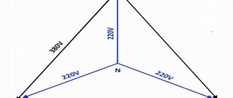
The three-phase alternating current electrical network is the most widely used among electrical energy transmission systems. The main thing in comparison with single-phase and two-phase systems is its efficiency. In a three-phase circuit, energy is transmitted through three wires, and the currents flowing in different wires are phase-shifted relative to each other by 120°, while the sinusoidal EMFs at different phases have the same frequency and amplitude.
Three-phase current (phase difference 120°)
Star and triangle
The three-phase stator winding of the electric motor is connected according to the circuit depending on the mains supply voltage. The ends of a three-phase winding can be: connected inside the electric motor (three wires come out of the motor), brought out (six wires come out), brought into a distribution box (six wires come out of the box, three wires come out of the box).
Phase voltage - potential difference between the beginning and end of one phase
Another definition for a star connection: phase voltage is the potential difference between the line wire and the neutral (note that the delta connection does not have a neutral)
Line voltage
- potential difference between two linear wires (between phases).
| Star | Triangle | Designation |
| Uл, Uф - linear and phase voltage, V, | ||
| Il, Iph - linear and phase current, A, | ||
| S — total power, W | ||
| P—active power, W |
Attention: Although the power for star and delta connections is calculated using the same formula, connecting the same electric motor in different ways to the same electrical network will result in different power consumption. In this case, incorrect connection of the electric motor can lead to melting of the stator windings.
Example: Let’s say the electric motor was connected in a star configuration to a three-phase alternating current network Ul=380 V (respectively Uph=220 V) and consumed current Il=1 A
Total power consumption:
S = 1.73∙380∙1 = 658 W.
Now let’s change the connection diagram to a “triangle”, the linear voltage will remain the same Uл=380 V, and the phase voltage will increase by the root of 3 times Uф=Uл=380 V. An increase in the phase voltage will lead to an increase in the phase current by the root of 3 times. Thus, the linear current of the delta circuit will be three times greater than the linear current of the star circuit. And therefore the power consumption will be 3 times greater:
S = 1.73∙380∙3 = 1975 W.
Thus, if the motor is designed to be connected to a three-phase AC network in a star configuration, connecting this electric motor in a delta configuration may lead to its failure.
If in normal mode the electric motor is connected in a delta circuit, then to reduce the starting currents during the start-up it can be connected in a star circuit. In this case, along with the starting current, the starting torque will also decrease.
Connecting an electric motor according to a star and delta circuit
Designation of the stator terminals of a three-phase electric motor
Designation of the terminals of the stator windings of newly developed
three-phase machines according to
GOST 26772-85
| Winding connection diagram, name of phase and output | Pin designation | |
| Start | End | |
| Open circuit (number of pins 6) | ||
| first phase | U1 | U2 |
| second phase | V1 | V2 |
| third phase | W1 | W2 |
| Star connection (number of pins 3 or 4) | ||
| first phase | U | |
| second phase | V | |
| third phase | W | |
| star point (zero point) | N | |
| Delta connection (number of pins 3) | ||
| first conclusion | U | |
| second conclusion | V | |
| third conclusion | W |
previously developed stator winding terminals
and modernized three-phase machines in accordance with
GOST 26772-85
| Winding connection diagram, name of phase and output | Pin designation | |
| Start | End | |
| Open circuit (number of pins 6) | ||
| first phase | C1 | C4 |
| second phase | C2 | C5 |
| third phase | C3 | C6 |
| Star connection (number of pins 3 or 4) | ||
| first phase | C1 | |
| second phase | C2 | |
| third phase | C3 | |
| zero point | ||
| Delta connection (number of pins 3) | ||
| first conclusion | C1 | |
| second conclusion | C2 | |
| third conclusion | C3 |
Standard diagram for connecting a three-phase motor to a single-phase network
The process of connecting a three-phase motor to 230 volts is simple. Usually the branch carries a sine wave, the difference is 120 degrees. A uniform phase shift is formed, ensuring smooth rotation of the stator electromagnetic field. The effective value of each wave is 230 volts. This will allow you to connect a three-phase motor to a household outlet. Circus trick: get three sine waves using one. The phase shift is 120 degrees.
In practice, this can be done with the help of special phase shifters. Not those used by high-frequency waveguide paths, but special filters formed by passive, less often active, elements. Fans of troubles prefer to use a real capacitor. If the motor windings are connected in a triangle, forming a single ring, we get phase shifts of 45 and 90 degrees, at least enough for unstable shaft operation:
Connection diagram for a three-phase motor using delta winding switching
- One winding is supplied with the socket phase. The wires pick up the potential difference.
- The second winding is powered by a capacitor. A phase shift of 90 degrees relative to the first is formed.
- On the third, due to the applied voltages, an oscillation slightly similar to a sinusoid is formed with a shift of another 90 degrees.
In total, the third winding is 180 degrees out of phase from the first. Practice shows that the layout is enough to work normally. Of course, the engine sometimes “sticks”, gets very hot, power drops, and efficiency suffers. Users put up with it when connecting an asynchronous motor to a three-phase network is excluded.
From purely technical nuances, let us add: a diagram of the correct wiring layout is given on the device body. More often it decorates the inside of the casing that hides the block, or is drawn nearby on a nameplate. Using the diagram as a guide, we will understand how to connect an electric motor with 6 wires (a pair for each winding). When the network is three-phase (often called 380 volts), the windings are connected in a star. A single point common to the coils is formed, where the neutral (conventional circuit electrical zero) is connected. Phases are supplied to the other ends. It turns out three - according to the number of windings.
It is clear how to handle a delta for connecting a three-phase 230 volt motor. Additionally, we provide a picture depicting:
- Electrical connection diagram of the windings.
- A working capacitor that serves the purpose of creating the correct phase distribution.
- A starting capacitor that facilitates spin-up of the shaft at initial speeds. Subsequently, it is disconnected from the circuit with a button and discharged with a shunt resistor (for safety and to be ready for a new start cycle).
Connecting a three-phase 230 volt motor with a triangle
The picture shows: winding A is energized at 230 volts. At C it is supplied with a phase shift of 90 degrees. Due to the potential difference, the ends of winding B generate a voltage shifted by 90 degrees. The outlines are far from the sinusoid familiar to school physicists. The starting capacitor and shunt resistor have been omitted for simplicity. We believe the location is obvious from the above. This technique will at the very least ensure normal operation of the engine. Using the key, the starting capacitor is closed, performing a start, disconnected from the phase, and discharged by a shunt.
The time has come to say: the capacitance indicated by the drawing 100 µF is practically selected taking into account:
- Shaft rotation speed.
- Engine power.
- Loads placed on the rotor.
You need to select a capacitor experimentally. According to our figure, the voltage of windings B and C will be the same. We remind you: the tester shows the current value. The voltage phases will be different, the waveform of winding B is non-sinusoidal. The effective value shows: equal power is delivered to the shoulders. Provides less stable operation of the installation. The motor heats up less, engine efficiency is optimized. Each winding is formed by inductive reactance, which also affects the phase shift between voltage and current
This is why it is important to choose the correct capacitance value. Ideal engine operating conditions can be achieved
Connection diagrams
Options for connecting the motor via a capacitor:
- connection diagram for a single-phase motor using a starting capacitor;
- connecting an electric motor using a capacitor in operating mode;
- connection of a single-phase electric motor with starting and running capacitors.
All these schemes are successfully used in the operation of asynchronous single-phase motors. Each case has its own advantages and disadvantages; we will consider each option in more detail.
Circuit with starting capacitor
The idea is that the capacitor is included in the circuit only at start-up; a start button is used, which opens the contacts after the rotor spins up, and by inertia it begins to rotate. The magnetic field of the main winding maintains rotation for a long time. Buttons with a group of contacts or relays are used as a short-term switch.
Since the circuit for short-term connection of a single-phase motor through a capacitor provides a button on a spring, which, when released, opens the contacts, this makes it possible to save money by making the starting winding wires thinner. To exclude an interturn short circuit, a thermal relay is used, which, when a critical temperature is reached, turns off the additional winding. In some designs, a centrifugal switch is installed, which opens the contacts when a certain rotation speed is reached.
Schemes and designs for adjusting the rotation speed and preventing overloads of the electric motor on the machine may be different. Sometimes a centrifugal switch is installed on the rotor shaft or on other elements rotating from it with a direct connection, or through a gearbox.
Under the influence of centrifugal forces, the load pulls back the springs with the contact plate, when the set rotation speed is reached, it closes the contacts, the relay switch de-energizes the engine or sends a signal to another control mechanism.
There are options when a thermal relay and a centrifugal switch are installed in the same structure. In this case, the thermal relay turns off the engine when exposed to a critical temperature or by the forces of the expanding weight of the centrifugal switch.
Due to the characteristics of an asynchronous motor, the capacitor in the additional coil circuit distorts the magnetic field lines, from round to elliptical, as a result of which power losses increase and efficiency decreases. Starting characteristics remain good.
Circuit with working capacitor
The difference between this circuit is that the capacitor does not turn off after start-up, and the secondary winding spins the rotor with pulses of its magnetic field throughout the entire operation. In this case, the power of the electric motor increases significantly; you can try to bring the shape of the electromagnetic field closer from an elliptical shape to a round one by selecting the capacitor capacitance. But in this case, the starting moment is longer and the starting currents are higher. The complexity of the circuit lies in the fact that the capacitance of the capacitor to equalize the magnetic field is selected taking into account current loads. If they change, then all the parameters will not be constant; to stabilize the shape of the magnetic field lines, you can install several capacitors with different capacities. If you turn on the appropriate capacitance when the load changes, this will improve performance, but significantly complicate the circuit and operation process.
Combined circuit with two capacitors
The best option for averaging operating characteristics is a circuit with two capacitors - starting and working.
Frequency regulation of single-phase asynchronous electric motors
So, more and more often there are proposals for frequency converters that can control single-phase asynchronous machines. Due to the fact that frequency generators are designed to work with three-phase machines, a special type of frequency converter is required to regulate the speed of single-phase machines. This is due to the fact that three-phase and single-phase machines have slightly different operating principles. Let's look at the connection diagram provided by one of the official manufacturers of frequency converters for single-phase machines:
This is a direct connection diagram. Where: F-phase of the supply voltage, N-neutral conductor, L1, L2 – motor windings, Ср – working capacitor.
And here is the connection diagram for the converter:
As we can see, the capacitor turns off when this circuit is turned on. Winding L1 is switched to the output of the phase A converter, and L2 to B. The common wire is connected to output C. Thus, we actually have a two-phase machine. The phase shift will now be implemented by the frequency converter, and not by the capacitor. The output of the converter will be a normal three-phase voltage.
This method of frequency regulation can hardly be called single-phase, since when the motor is powered directly from the network, it is necessary to restore the circuit with the capacitor again. Moreover, this method of frequency regulation is NOT SUITABLE for machines with a starting winding, since the resistance of the working and starting windings is not equal, and asymmetry will appear.
We can conclude that this type of frequency control is not suitable for all electric motors, but only for capacitor motors. Moreover, with such a connection scheme, it is necessary to reconnect the windings inside the electric motor (in the motor terminal box), which after reconnection will not allow it to operate directly from the network. Therefore, if you are going to power an electric motor from a single-phase network through a frequency converter, then it may be worth buying a converter that is powered from a single-phase network, and the motor is a regular, three-phase one. This is better from the point of view of the operation of the machine itself, and there are also no modifications inside the electric machine. If you are going to upgrade the system in this way, then carefully study the characteristics of the electric motor and converter in order to avoid wastage of funds or failure of system elements.
In addition to the common 3-phase asynchronous motors, single-phase motors are offered on the market. Most often they are pumps and fans. The most popular units in industry and in everyday life. And then the question arises? How to control them and regulate speed. There are a great many ways. But the most effective is when a frequency converter is connected for a single-phase motor.
From this article you will learn:
Hi all! Gridin Semyon is with you, and in this post we will talk to you about the nuances of controlling single-phase asynchronous motors. Which control method is better? Let's look at this question - frequency control of the engine in more detail.
How to decide on engine type
If the engine is new, then there will be no special problems, since its nameplate indicates the engine type and other data. If the engine has been repaired, then determining its type is associated with some difficulties: the plate could simply be lost or damaged mechanically. Therefore, in such cases, it is better to know how to independently determine the type of engine.
Brushed motors
Brushed motor
Determining whether a motor is commutator or asynchronous is not at all difficult, since they have different structures. A characteristic difference between a commutator motor is the presence of brushes that are stationary, as well as a commutator that rotates and consists of a set of copper plates. Brushes are pressed against these plates, transmitting electric current to the motor armature winding.
The advantage of such engines is that they accelerate quickly and allow you to get high speeds. In addition, by changing the polarity, it is possible to change the direction of rotation of the device. No less important can be considered the factor that you can easily organize control of the engine speed, with its adjustment within a wide range.
A significant disadvantage of commutator engines is their increased noise during operation, especially at high speeds. As for low speeds, the performance of these engines can be considered quite acceptable. It should also be taken into account that the friction of the brushes and commutator leads to wear of both the brushes and the commutator. As a result, you have to change the brushes or grind the commutator. If you do not constantly monitor the condition of the brushes and commutator, there is a high probability that the device will have to be repaired.
Checking the insulation resistance of the stator windings
If the engine was stored in an unheated room, it came into contact with moist air and became damp. Its insulation is broken and can create leakage currents. Therefore, its quality must be assessed by electrical measurements.
A tester in ohmmeter mode is not always able to detect such a violation. It will only show an obvious defect: the power of its current source is too low and does not provide an accurate measurement result. To check the condition of the insulation, it is necessary to use a megohmmeter - a special device with a powerful power source that ensures that an increased voltage of 500 or 1000 volts is applied to the measuring circuit.
An assessment of the insulation condition must be carried out before applying operating voltage to the windings. If leakage currents are detected, you can try to dry the engine in a warm, well-ventilated environment. Often this technique allows you to restore the functionality of the electrical circuit assembled inside the stator core.
About capacitors
Network capacitor value
In normal mode, connection via a three-phase network can be made only by one of the circuit options, i.e. star or triangle. That is why the power supply mode connected according to the triangle diagram allows a voltage of 380 as the nominal voltage. In the case of single-phase, its value will be 220 volts. This value will be lower than in the delta circuit and is therefore considered safe for electrical mode. However, when the voltage decreases, indicators such as electrical power and engine shaft power decrease.
So one of the windings must be connected directly to the electrical network. In order for the remaining windings to get the maximum output, they must be used in combination when connected using a capacitor, which creates phase shifts in the voltage across them. And as a result, we get a connection similar to a triangle, but with a single-phase circuit.
Also here, the capacitance value of the capacitor will play a significant role, since it creates a movement of the magnetic field to rotate the rotor.
So, when starting the engine, there may not be enough capacitor capacity. To increase the starting torque, it is necessary to increase its capacity. But in the process, it is possible that this added capacity is unnecessary and with the lowest value the work was more efficient. Therefore, to optimize these indicators, it is better to use 2 heat exchangers. One must be constantly connected to the network, and the second is connected when the electric motor starts.
Another feature of a capacitor when connected to a three-phase network is its relationship to the windings, phase and neutral wires. It can be connected either to the zero phase and winding or to the phase and winding. Depending on which connection was used, it depends in which direction the rotor rotates. So by adding just one switch to the circuit, you can control the movement of the shaft.
An electrical network parameter such as inductance is also related to the phase shift. Inductance is created by a different ratio of voltage and current. However, if a choke is connected in place of the capacitor. Then it will help to significantly reduce the effect of the current in the starting winding, which will create a weak magnetic field in the windings and the engine will not start.
Therefore, the capacitor is the only element suitable for effectively moving the stator magnetic fields in a motor connected to a single-phase network.
Types of capacitors
To connect electrical units 380 to 220 Volts, the following paper-type capacitors with a metal case are mainly used - MBGO, KBP, MBGP. However, all these types are very large in size and have a small capacity.
There is a third type - SVV capacitors. They are round and lamellar. They are of high quality, have a large capacity, and are not large in size. It is this type that is recommended by experts to use when connecting a 380 to 220 electric motor.