The operation of a single-phase electric motor is based on the use of alternating electric current by connecting to single-phase networks. The voltage in such a network must correspond to the standard value of 220 Volts, frequency - 50 Hertz. Motors of this type are primarily used in household appliances, pumps, small fans, etc.
The power of single-phase motors is sufficient for the electrification of private houses, garages or summer cottages. Under these conditions, a single-phase electrical network with a voltage of 220 V is used, which places some demands on the process of connecting the motor. A special circuit is used here, which involves the use of a device with a starting winding.
Single-phase and three-phase asynchronous motors
We agreed - three-phase commutator motors are difficult to obtain; the current section deals with asynchronous machines. We list the varieties:
- Three-phase asynchronous motors are equipped with a number of outputs from three to six working windings minus various fuses, internal relays, and various sensors. The stator coils inside are connected by a star, making it impossible to directly connect to a single-phase network.
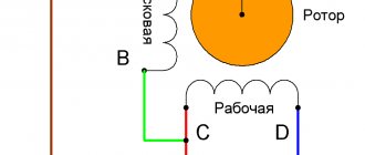
- Single-phase motors equipped with a starting winding are, among other things, equipped with a pair of contacts leading to a centrifugal limit switch. The miniature device breaks the chain when the shaft is untwisted. The starting winding catalyzes the initial stage. Further action will interfere, reducing the efficiency of the engine. The design is usually called bifilar. The starting winding is wound with double wire, reducing reactance. Helps reduce the capacitance of the capacitor - critical. A striking example of single-phase asynchronous motors with a starting winding are the compressors of household refrigerators.
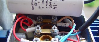
- The capacitor winding, different from the starting winding, operates continuously. We will find the motors inside the floor fans. The capacitor provides a phase shift of 90 degrees, allowing you to choose the direction of rotation and maintain the desired shape of the electromagnetic field inside the rotor. Typically the capacitor is mounted on the motor housing.
- Small asynchronous motors used in hoods and fans can be started without a capacitor at all. The initial movement is formed by the flapping of the blades, or by the curvature of the rotor wiring (grooves) in the desired direction.
Let's learn how to distinguish single-phase asynchronous motors from three-phase ones. In the latter case, there are always three equal windings inside. Therefore, you can find three pairs of contacts that, when examined by a tester, give the same resistance. For example, 9 ohms. If the windings are connected by a star inside, there will be three terminals with the same resistance. Of these, any pair gives identical readings displayed on the multimeter screen. The resistance is equal to two windings each time.
Because current must flow out, sometimes a three-phase motor has a neutral terminal. The center of the star, with each of the other three wires, gives identical resistance, half that shown by the pairwise continuity. The above symptoms speak eloquently: the motor is three-phase, alien to the topic of today’s conversation.
The winding motors discussed in this section contain two. One starting or capacitor (auxiliary). There are usually three or four conclusions. If there is no capacitor decorating the case, you can try to reason, puzzled by the purpose of the contacts, as follows:
- There are four pins - you need to measure the resistance. Usually they ring in pairs. The resistance is lower - we found the main winding, connected to a 230 volt network without a capacitor. Polarity does not matter; the direction of rotation is set by the way the auxiliary winding is turned on, by switching the coils. Simply put, connect a single-phase electric motor of a characteristic type with only one main winding - in the initial period of time the shaft stands upright. Wherever you spin, there will be rotation. Beware of starting with your hand - it will break.
- We see three conclusions. Inside, the ends of the coils are connected to form a star. Neutral (circuit zero) is supplied. Regarding the other two terminals, the pairwise resistance will be the greatest (equal to both windings connected in series). The smallest value, as before, will be the working winding; the starting phase passes through the capacitor. Will provide a shift in the right direction. Typically, such a motor rotates unidirectionally; it is impossible to physically change the polarity of the capacitor. However, there is information (we’ll check the diagrams another time): by feeding the working coil with voltage through a capacitor, turning on the starting coil directly, we will perform a reverse. The possibility of connecting a 3-wire electric motor, implementing reverse rotation, is not mentioned in the literature.
Connection
Calculating the values of their capacitances is relatively simple: for the working one 0.75 μF per 1 kW of power, for the starting one - 2.5 times more. Its structure is slightly different from a conventional single-phase asynchronous motor.
A circuit with a working, always-on capacitor works better in nominal mode, but has mediocre starting characteristics. The operating voltage of these capacitors should be 1.5 times higher than the network voltage, that is, for network B we take capacitors with an operating voltage of B and higher.
But despite this, they are widely used in the production of household appliances. These motors have lower efficiency values.
After assembling the electromagnetic starter circuit, you should connect the power section. Its structure is slightly different from a conventional single-phase asynchronous motor. Its power can range from five to ten kilowatts. In addition to the presence of two phases, it is required that one winding be shifted relative to the other by a certain angle.
We recommend: current volumes and standards of electrical equipment testing
Operating principle of a commutator motor
Starting scheme: Starting is carried out by a magnetic field, which rotates the moving part of the motor. Next example.
Single-phase asynchronous electric motors Design and principle of operation The power of such a single-phase motor B can, depending on the design, range from 5 W to 10 kW. On which of them there is no difference, the direction of rotation does not depend on it. Look at the photo and you can clearly see that the wire cross-sections are different. When connecting the device in question, several types of connections are made. That is, if the auxiliary winding of a single-phase motor is starting, its connection will occur only during the start-up, and if the auxiliary winding is a capacitor, then its connection will occur through a capacitor, which remains turned on during engine operation.
Connection diagram for a 220 Volt commutator motor
These electricity ratings are available in all residential premises in our country, and as a result, single-phase motors are extremely popular. We need an initial push. Current is supplied to the rotor windings through brushes in contact with the commutator plates, to which the ends of the rotor windings are connected. Connection diagram 2 Connecting an asynchronous single-phase electric motor to the network.
The function of the centrifugal switch is to cut off the starting phase when the rotor reaches its rated speed. Further rotation of the rotor is ensured by the pulsating magnetic field of the working phase, as already described in the previous paragraph. Two and three-phase motors It is possible to connect a 2 or 3-phase motor to a single-phase power source. how to connect a three-phase motor to a single-phase network
How to connect a frequency converter
To connect a frequency converter to equipment, first of all you need to make sure that the characteristics of such a device are suitable for working with a specific electric motor.
It is also important that the supply voltage allows the use of this frequency converter
When installing and connecting the emergency control system, it is necessary that the operating conditions correspond to the class of protection from moisture and dust, and that all distances from moving parts of machines and mechanisms, from human passages and electrical equipment and equipment are maintained.
IF connection diagram
Frequency converters are available for both three-phase and single-phase networks. At the same time, a three-phase frequency converter can also be connected to a single-phase network using a “triangle” circuit, which is additionally equipped with a special capacitor unit (in this case, the power drops significantly and the efficiency of the device decreases). The three-phase converter is connected to the corresponding network according to the “star” circuit.
The frequency converter can be controlled using contactors built into various relay circuits, microprocessor controllers and computer equipment, as well as manually. Therefore, when connecting automated systems, the participation of specialists in setting up such equipment is required.
The principle of connecting frequency converters is generally the same, but may differ slightly for different models. Therefore, the right decision would be to study the instructions before connecting, compare the characteristics of the devices and make sure that the device is connected according to the scheme proposed by the manufacturer.
For three-phase electric motor
For a three-phase electric motor, the connection principle is as follows: phase conductors are connected to the terminal blocks at the output of the three-phase frequency converter to each output, and phases of the supply voltage are connected to the input. In this case, a “star” connection scheme is always implemented in the motor. When connecting a three-phase motor through a frequency converter to a single-phase network, a “triangle” circuit is used.
For single-phase electric motor
For a single-phase electric motor, it is necessary to connect the phase and neutral conductors to the frequency converter, and the motor windings are connected to the corresponding terminals at the output of the frequency converter. For example, winding L1 will be connected to terminal A of the converter, winding L2 to terminal B, and the common wire to terminal C. If a capacitor motor is used, then the phase from the frequency converter is connected to the motor, and the capacitor provides a phase shift.
In all cases, when connecting frequency converters and electric motors, you should always use protection devices: circuit breakers and RCDs designed for high inrush currents, and be sure to connect the grounding conductor to the device housings
It is also important to pay attention to the cross-section of the electrical cable conductors to which the connection will be made - the cross-section must correspond to the parameters of the connected frequency converter and load
Watch this video on YouTube
What is a frequency converter, main types and what is the principle of operation
How to connect a 3-phase electric motor to a 220 volt network through a capacitor
Scheme of operation of the soft starter, its purpose and design
Design, types and principle of operation of asynchronous electric motors
How to connect a single-phase electric motor - circuit with a capacitor
Checking different types of electric motors using a multimeter
One phase instead of three
This will not affect the rotation speed of the rotor, but the power of such an electric machine will drop. Depending on the load on the shaft, capacitor capacity, connection diagram, losses are 30–50%.
It is worth immediately noting that not all brands of devices operate on a single-phase circuit. But still, the majority allows such manipulations to be carried out on themselves.
You should always pay attention to the attached signs. There are all the characteristics, looking at which you can see what model it is and where it will work
The second (B) shows: the electric machine is designed for 380 V, star switched on. Theoretically, it is possible to switch to a lower voltage, but to do this you need to disassemble the housing, look for the connection of the windings and switch them to a triangle. You can, of course, not switch anything by simply installing a capacitor. However, the power losses will be colossal.
If the sign says: Δ/Ỵ 127/220, then such a device can only be connected to a 220 V network with a star, otherwise it will burn out!
Reversing the direction of movement of the engine
If, after connecting, the motor works, but the shaft does not rotate in the direction you want, you can change this direction. This is done by changing the windings of the auxiliary winding. This operation can be performed by a two-position switch, the central contact of which is connected to the output from the capacitor, and to the two outer terminals from “phase” and “zero”.
How to distinguish on a single-phase motor
Single-phase motors are equipped with two types of winding so that their rotor can rotate, since only one is not enough for this. Therefore, before connecting the motor, you need to figure out which skein is the main one and which is the auxiliary one. There are several ways to do this.
By color coding
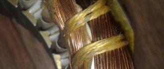
What type a particular skein is can be determined by color markings during a visual inspection of the engine. As a rule, red wires are of the working type, but blue wires are of the auxiliary type.
But all rules have their exceptions, so you should always pay attention to the electric motor tag, on which a decoding of all markings is applied
However, if the engine has already been repaired or there is no tag on it, this method of checking is not effective. In the first case, during repair work, the internal contents of the motor could completely change, and in the second, there is no way to accurately decipher the color symbols. In addition, sometimes there may be no markings at all. Therefore, in such situations, it is better to resort to another, more reliable method.
By wire thickness
The thickness of the wires that come out of a low-power electric machine will help distinguish the starting coil from the working one. Since the auxiliary one works for a short time and does not experience serious load, the wires related to it will be thinner.
But even if it catches your eye, you shouldn’t rely on that alone. Therefore, many always measure the resistance of wires.
Using a multimeter
A multimeter is a special device that allows you to measure the resistance of wires, as well as their integrity. To do this, you must follow the following algorithm:
- Take a multimeter and select the desired function.
- Remove the insulation from the motor wires and connect any two of them to the probes of the device. This is how the resistance force between the two motor wires is measured.
- If no numerical values appear on the device screen, then you need to replace one of the wires and then repeat the procedure. The readings obtained will refer to the terminals of one skein.
- Connect the probes of the measuring device to the remaining wires and record the readings.
- Compare your results. Electrical wires with a stronger resistance will belong to the starting coil, and those with a weaker resistance will belong to the working coil.
Once the measurements have been determined and it becomes clear which electrical wires belong to which coil, it is recommended to mark them in any convenient way. This will allow you to skip the resistance measurement procedure when connecting the motor in the future.
There are several ways to distinguish where the starting winding is and where the working winding is of a single-phase motor. However, the most effective of them is to measure the resistance of the electrical wires coming from a low-power electric motor using a multimeter.
Shortcuts
How to replace the PVS button.
The question arises as to what can replace the PVS button. In this article we will figure out how to connect two magnetic starters and a push-button post so that they replace a button with a start contact.
Attention!
Be very careful when working with electricity!
Let's start by getting to know the magnetic starter. It has 3 main, power pairs of contacts L 1- T 1; L 2- T 2; L 3- T 3. In normal position these contacts should be open. There is also an additional pair, but we will not consider it, since in this case we do not need it.
There are also contacts A1–A2. Contact A2 is often duplicated on the reverse side.
These are the outputs of the electromagnet coil. When power is applied to them, the electromagnet is triggered and the power contacts are closed.
The electromagnet can be designed for different voltages, but we need 220-230 Volts.
We install the power part. It must be made with a wire capable of withstanding the power of your engine. One of the starters will act as a starter and will only operate while the “Start” button is held down. Let’s call the second one “working”; it will be activated when the “Start” button is pressed and turned off when the “Stop” button is pressed. Connect contacts L 1 of both starters with a jumper, and connect the power cable to contacts L 1 and L 2 of the working starter. Let's draw conclusions to the electric motor from the working starter: T 2 is the common wire, T 1 is the working wire. From the launcher T 1 - launcher.
Then we install the control circuit. A thin mounting wire is suitable for it. We place jumpers between contacts L 1 and A1 of both starters.
We carefully examine the push-button post. The contacts on it are normally closed and normally open.
From contacts T 3 of both starters we place jumpers on contact A2 of the working starter.
Circuit without power section:
Power section diagram for a single-phase motor with a starting winding:
Good luck with your DIY projects.
:
Hello! I'd like to see the diagram, please!
Connecting a single-phase motor
Before you start connecting any electric motor, you must be completely sure that the motor is working. Carry out a full inspection to check the quality of the bearings and the absence of play in the rotor seats and in the engine covers. Check the windings for short circuits between each other and the housing.
Also, when connecting, you must follow safety precautions, be extremely careful and work without haste.
To connect a single-phase electric motor with a starting winding, we need a switch with a starting contact - PNVS. The number after the letters indicates the current strength for which the switch is designed.
note
In the previous article, I told you how to determine the type of motor, whether it is three-phase or single-phase.
And if you doubt whether it is a capacitor motor or one with a starting winding, then you must first connect the motor as with a starting winding, and if it does not start, then it is a capacitor motor.
In order to find out which of the two windings is working, it is necessary to measure their resistance. The coil that has the least resistance is the working one. The exception is a very small percentage of capacitor motors, in which both the working winding and the capacitor winding are the same and have the same resistance.
The starting winding is connected only to start the engine and is turned off after the engine has picked up speed. Only the working winding remains in operation. A correctly wound engine, with an inspection carried out without load on the shaft, reaches the required speed in no more than a few seconds, but more often - instantly. Therefore, during a test run, the engine must be securely fastened.
We connect one end of the working and starting ends together and connect it to one of the extreme marks of the button. This will be the common wire. We connect the second end of the working winding to the second extreme mark of the button. And we connect the remaining wire of the trigger coil to the middle mark of the button.
In this case, we use the stamps on only one side of the button. Three marks on the other side remain free for now. We connect the power cord to the outer two of them. And to the central mark we connect a jumper from the outer mark opposite which one working wire is connected.
We close the button cover, secure the motor, do a test switch on and off the button to make sure it is working and to know that it is in the off state. We plug the plug into the socket, press the start button and hold it until the engine speeds up.
Important
But no more than a few seconds. Then release the button. If the motor hums but does not start to rotate, then the motor is a capacitor motor and must be connected according to a different circuit.
Therefore, any starter, toggle switch or switch that can open and close two contacts at the same time is suitable.
We connect one end of the working and one end of the starting windings together and bring them to one of the switch marks. We connect the second ends of the windings to different terminals of the capacitor and at the same time we also connect the wire from the working coil to the second mark of the switch. We connect the power cord to the opposite marks of the switch.
We switch the toggle switch to the off position, check that the engine is securely fastened, plug the plug into the socket and turn on the toggle switch. The motor without load on the shaft should start instantly.
In order for a single-phase motor to rotate in the other direction, it is necessary to swap the leads of one of the windings.
If we need the engine to rotate in one direction or the other, then we need to install a reverse toggle switch. Moreover, place it so that we cannot switch it while the engine is running. This applies to a capacitor motor. The toggle switch should have 2 or 3 positions and have six pins.
In one position, the two middle terminals are closed with the two extreme ones, and in the other with the other two extreme ones. We connect two wires of one of the motor coils to the central marks of the switch, and we connect the outer marks diagonally and take two wires from them that we connect to where the ends of the winding were disconnected. Now, when the toggle switch is switched, the engine will start in the other direction. Reversing circuit of a single-phase motor with a starting winding and an NVD button.
I will tell you how to select a capacitor for a capacitor motor in one of the following articles.
Switching to the desired voltage
First we need to make sure that our engine has the necessary parameters. They are written on a tag attached to his side. It should indicate that one of the parameters is 220V. Next, let's look at the connection of the windings. It is worth remembering this pattern of the circuit: star - for lower voltage, triangle - for higher voltage. What does this mean?
Voltage increase
Let's say the tag says: Δ/Ỵ220/380. This means that we need a delta connection, since most often the default connection is 380 volts. How to do it? If the electric motor in the burner has a terminal box, then it is not difficult. There are jumpers there, and all you need to do is switch them to the desired position.
In this situation this does not cause any difficulties. The main thing to remember is that there is a beginning and an end to the coils. For example, let’s take as a starting point the ends that were brought out into the boron of the electric motor. This means that what is soldered is the ends
Now it’s important not to confuse
We connect like this: we connect the beginning of one coil to the end of the other, and so on.
As you can see, the scheme is simple. Now the engine, which was connected for 380, can be connected to a 220 volt network.
Voltage reduction
Let's say the tag says: Δ/Ỵ 127/220. This means a star connection is required. Again, if there is a terminal box, then everything is fine
What if not, and our electric motor is turned on in a triangle? And if the ends are not signed, then how to connect them correctly? After all, here it is also important to know where the coil winding begins and where the end is. There are some ways to solve this problem
First, let's move all six ends apart and use an ohmmeter to find the stator coils themselves.
We take a regular battery and connect it to ends a1-a2. We connect an ohmmeter to the other two ends (c1-c2).
At the moment the contact with the battery is broken, the arrow of the device will swing to one side. Let's remember where it swung and turn on the device to ends c1-c2, without changing the polarity of the battery. Let's do it all over again.
If the arrow deviates in the other direction, then we swap the wires: we mark c1 as c2, and c2 as c1. The point is that the deviation is the same.
Now we connect the battery, observing polarity, to ends c1-c2, and the ohmmeter to a1-a2.
We ensure that the needle deflection on any reel is the same. Let's double check again. Now one bundle of wires (for example, with the number 1) will be the beginning, and the other will be the end.
We take three ends, for example, a2, b2, c2, and connect them together and isolate them. This will be a star connection. As an option, we can output them directly to the terminal block and label them. We paste the connection diagram onto the lid (or draw it with a marker).
Switching triangle - star done. You can connect to the network and work.
Connection diagrams for single-phase asynchronous motors
With starting winding
To connect a motor with a starting winding, you will need a button in which one of the contacts opens after switching on. These opening contacts will need to be connected to the starting winding. In stores there is such a button - this is PNDS. Its middle contact closes for the holding time, and the two outer ones remain in a closed state.
Appearance of the PNVS button and the state of the contacts after the “start” button is released"
First, using measurements, we determine which winding is working and which is starting. Typically the output from the motor has three or four wires.
Consider the option with three wires. In this case, the two windings are already combined, that is, one of the wires is common. We take a tester and measure the resistance between all three pairs. The working one has the lowest resistance, the average value is the starting winding, and the highest is the common output (the resistance of two windings connected in series is measured).
If there are four pins, they ring in pairs. Find two pairs. The one with less resistance is the working one, the one with more resistance is the starting one. After this, we connect one wire from the starting and working windings, and bring out the common wire. A total of three wires remain (as in the first option):
- one from the working winding is working;
- from the starting winding;
- general.
We work further with these three wires - we use them to connect a single-phase motor.
With all these
Connecting a single-phase motor with a starting winding via the PNVS button Connecting a single-phase motor
We connect all three wires to the button. It also has three contacts. Be sure to place the starting wire on the middle contact (which closes only during the start), the other two - on the outer ones (arbitrarily)
We connect a power cable (from 220 V) to the extreme input contacts of the PVNS, connect the middle contact with a jumper to the working one (note! not to the common one). That's the whole circuit for switching on a single-phase motor with a starting winding (bifolar) through a button
Condenser
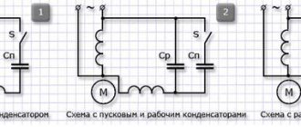
When connecting a single-phase capacitor motor, there are options: there are three connection diagrams and all with capacitors. Without them, the engine hums, but does not start (if you connect it according to the diagram described above).
Connection diagrams for a single-phase capacitor motor
The first circuit - with a capacitor in the power supply circuit of the starting winding - starts well, but during operation the power it produces is far from rated, but much lower. The connection circuit with a capacitor in the connection circuit of the working winding gives the opposite effect: not very good performance at start-up, but good performance. Accordingly, the first circuit is used in devices with heavy starting (concrete mixers, for example), and with a working condenser - if good performance characteristics are needed.
Circuit with two capacitors
There is a third option for connecting a single-phase motor (asynchronous) - install both capacitors. It turns out something between the options described above. This scheme is implemented most often. It is in the picture above in the middle or in the photo below in more detail. When organizing this circuit, you also need a PNVS type button, which will connect the capacitor only during the start time, until the motor “accelerates”. Then two windings will remain connected, with the auxiliary winding through a capacitor.
Connecting a single-phase motor: circuit with two capacitors - working and starting
When implementing other circuits - with one capacitor - you will need a regular button, machine or toggle switch. Everything connects there simply.
Selection of capacitors
There is a rather complex formula by which you can calculate the required capacity accurately, but it is quite possible to get by with recommendations that are derived from many experiments:
- The working capacitor is taken at the rate of 0.7-0.8 µF per 1 kW of engine power;
- starting - 2-3 times more.
The operating voltage of these capacitors should be 1.5 times higher than the network voltage, that is, for a 220 V network we take capacitors with an operating voltage of 330 V and higher. To make starting easier, look for a special capacitor in the starting circuit. They have the words Start or Starting in their markings, but you can also use regular ones.
Changing the direction of motor movement
If, after connecting, the motor works, but the shaft does not rotate in the direction you want, you can change this direction. This is done by changing the windings of the auxiliary winding. When assembling the circuit, one of the wires was fed to the button, the second was connected to the wire from the working winding and the common one was brought out. This is where you need to switch the conductors.
What it might look like in practice
Online calculation of motor capacitor capacity
Enter data for calculating capacitors - motor power and efficiency
There is a special formula that can be used to calculate the required capacity accurately, but you can easily get by with an online calculator or recommendations that are derived from many experiments:
Capacitors must be non-polar, that is, not electrolytic. The operating voltage of these capacitors must be at least 1.5 times higher than the network voltage, that is, for a 220 V network we take capacitors with an operating voltage of 350 V and higher. To make starting easier, look for a special capacitor in the starting circuit. They have the words Start or Starting in their markings.
Starting capacitors for motors
These capacitors can be selected using the method from smallest to largest. Having thus selected the average capacity, you can gradually add and monitor the operating mode of the engine so that it does not overheat and has enough power on the shaft. Also, the starting capacitor is selected by adding until it starts smoothly without delays.
Single-phase electric motor with asymmetric stator magnetic circuit
Stator
Such a single-phase motor is made with pronounced poles on an asymmetrical laminated core. Rotor
— short-circuited “squirrel cage” type.
This electric motor does not require the use of phase-shifting elements to operate. The disadvantage of this engine is low efficiency.
A single-phase motor operates using alternating electric current and is connected to single-phase networks. The network must have a voltage of 220 Volts and a frequency of 50 Hertz.
Electric motors of this type are used mainly in low-power devices:
- Household appliances.
- Low power fans.
- Pumps.
- Machines for processing raw materials, etc.
Models are available with power from 5 W to 10 kW.
The values of efficiency, power and starting torque for single-phase motors are significantly lower than for three-phase devices of the same size. The overload capacity is also higher for 3-phase motors. Thus, the power of a single-phase mechanism does not exceed 70% of the power of a three-phase mechanism of the same size.
device
Device:
- It actually has 2 phases, but only one of them does the work, which is why the motor is called single-phase.
- Like all electric machines, a single-phase motor consists of 2 parts: stationary (stator) and moving (rotor).
- It is an asynchronous electric motor, the stationary component of which has one working winding, connected to a single-phase alternating current source.
The strengths of this type of engine include the simplicity of the design, which is a rotor with a squirrel-cage winding. The disadvantages are low starting torque and efficiency.
The main disadvantage of single-phase current is its inability to generate a magnetic field that performs rotation. Therefore, a single-phase electric motor will not start on its own when connected to the network.
In the theory of electrical machines, the rule applies: in order for a magnetic field to arise that rotates the rotor, there must be at least 2 windings (phases) on the stator. It is also required to shift one winding by a certain angle relative to the other.
During operation, alternating electric fields flow around the windings:
- In accordance with this, the so-called starting winding is located on the stationary section of the single-phase motor. It is shifted 90 degrees relative to the working winding.
- A current shift can be obtained by including a phase-shifting link in the circuit. Active resistors, inductors and capacitors can be used for this.
- 2212 electrical steel is used as the basis for the stator and rotor.
Three-phase
The AC induction motor has a very simple design compared to other types of electrical machines. It is quite reliable, which explains its popularity. Three-phase models are connected to an alternating voltage network with a star or delta. Such electric motors also differ in operating voltage: 220–380 V, 380–660 V, 127–220 V.
As a rule, such electric motors are used in production, since three-phase voltage is most often used there. And in some cases it happens that instead of 380 V there is three-phase 220. How to connect them to the network so as not to burn the windings?
Operating principle
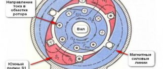
The principle of operation of an electric motor demonstrates the simplest experiment that we were all shown at school - the rotation of a frame with current in the field of a permanent magnet.
The frame with current is an analogue of the rotor, the stationary magnet is the stator. If current is applied to the frame, it will turn perpendicular to the direction of the magnetic field and freeze in this position. If you force the magnet to spin, the frame will rotate at the same speed, that is, synchronously with the magnet. We have a synchronous electric motor. But our magnet is a stator, and by definition it is motionless. How to make the magnetic field of a stationary stator rotate?
First, let's replace the permanent magnet with a current-carrying coil. This is the winding of our stator. As is known from the same school physics, a coil with current creates a magnetic field. The latter is proportional to the magnitude of the current, and the polarity depends on the direction of the current in the coil. If we apply alternating current to the coil, we get an alternating field.
A very clear analogy with a clock will help us. What vectors constantly rotate before our eyes? These are the hour hands. Let's imagine that there is a clock hanging in the corner of the room. The second hand rotates one full revolution per minute. An arrow is a vector of unit length.
The shadow that the arrow casts on the wall varies as a sine with a period of 1 minute, and the shadow cast on the floor changes as a cosine. Or a sine phase shifted by 90 degrees. But a vector is equal to the sum of its projections. In other words, the arrow is equal to the vector sum of its shadows.
Connection diagram for a single-phase motor via a capacitor
In the second case, for motors with a working capacitor, the additional winding is permanently connected through the capacitor.
Based on the information on the motor tag, you can determine which system is used in it. The complexity of the circuit lies in the fact that the capacitance of the capacitor to equalize the magnetic field is selected taking into account current loads.
Here, each winding is used for its own operating voltage, hence the power. The capacity is calculated based on the operating voltage and current, or the nameplate power of the motor. By briefly connecting a starting capacitor on the motor shaft, a powerful starting torque is created, and the starting time is reduced significantly.
Due to the complexity of the calculation formulas, it is customary to select containers based on the above proportions. Calculating the capacitance of a motor capacitor There is a complex formula that can be used to calculate the required exact capacitance of the capacitor. In these motors, the working and starting windings are the same according to the design of three-phase windings. After discarding the device for scrap, in most cases, electric motors remain operational and can serve for quite a long time in the form of homemade electric pumps, sharpeners, machine tools, fans and lawn mowers.
Article on the topic: Types of electrical installation work according to estimates
Conclusion
The result is two differently directed flows with a rotation speed different from the main field. This is a star winding diagram. Red arrows are the voltage distribution in the motor windings, indicating that the single phase voltage in V is distributed on one winding, and the linear voltage V is distributed on the other two windings.
After starting the engine, the capacitors contain a certain amount of charge, so touching the conductors is prohibited. In this winding, which is also called the working winding, the magnetic flux changes with the frequency at which current flows through the winding. You can calculate which wires belong to which winding by measuring the resistance. The winding with less resistance is working. The stator of a single-phase electric motor contains a single-phase winding, which distinguishes it from a three-phase one.
Motors with a rotation height of more than 90 mm are available in cast iron. This scheme eliminates the electronics unit, and therefore, the motor will immediately operate at full power from the moment of start - at maximum speed, when starting, it literally explodes with force from the starting electric current, which causes sparks in the collector; There are electric motors with two speeds. This is the necessary reserve to compensate for power losses during start-up - the creation of a rotating moment of the magnetic field. Afterwards it is turned off by a special device - a centrifugal switch or a start-up relay in refrigerators.
The generator can act as an engine, and it, in turn, can act as a generator. On the body of a single-phase asynchronous electric motor there must be a connection diagram, which indicates the terminals of the main and additional windings, as well as the capacitance of the capacitor. In this case, the engine hums, the rotor remains in place. Connecting a single-phase electric motor
Design and operating principle
The electric motor is connected through a capacitor because one winding on the stator of a 220 V AC electric motor creates a magnetic field that compensates for its impulses by changing polarity with a frequency of 50 Hz. In this case, the engine hums, the rotor remains in place. To create torque, additional connections are made to the starting windings, where the electrical phase shift will be 90° relative to the working winding.
Do not confuse geometric concepts of position angle with electrical phase shift. In the geometric dimension, the windings in the stator are placed opposite each other.
To achieve this technically, the design of the electric motor provides a large number of mechanical parts and electrical circuit components:
- stator with main and additional starting windings;
- squirrel cage rotor;
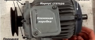
- boron with a group of contacts on the panel;
- capacitors;
- centrifugal switch and many other elements shown in the above picture.