Electric motor power calculation
Calculation of electric motor power by current can be done using our online calculator:
The result obtained can be rounded to the nearest standard power value.
Standard values of electric motor power : 0.25; 0.37; 0.55; 0.75; 1.1; 1.5; 2.2; 3.0; 4.0; 5.5; 7.5; eleven; 15; 18.5; 22; thirty; 37; 45; 55; 75 kW, etc.
Engine power is calculated using the following formula:
P=√3UIcosφη
- U - Rated voltage (voltage to which the electric motor is connected);
- I - Rated current of the electric motor (taken from the passport data of the electric motor , and in their absence is determined by calculation);
- cosφ - Power factor - the ratio of active power to total power (taken from 0.75 to 0.9 depending on the power of the electric motor);
- η - Efficiency factor - the ratio of the electrical power consumed by the electric motor from the network to the mechanical power on the motor shaft (taken from 0.7 to 0.85 depending on the power of the electric motor);
Calculation of electric current by power: formulas, online calculation, selection of machine
When designing electrical wiring in a room, you need to start by calculating the current strength in the circuits.
An error in this calculation can be costly later. An electrical outlet can melt if exposed to too much current. If the current in the cable is greater than the calculated current for a given material and core cross-section, the wiring will overheat, which can lead to melting of the wire, a break or short circuit in the network with unpleasant consequences, among which the need to completely replace the electrical wiring is not the worst thing.
It is also necessary to know the current strength in the circuit to select circuit breakers, which should provide adequate protection against network overload.
note
If the machine is set with a large margin at its nominal value, by the time it is triggered, the equipment may already be out of order.
But if the rated current of the circuit breaker is less than the current that appears in the network during peak loads, the circuit breaker will drive you crazy, constantly cutting off power to the room when you turn on the iron or kettle.
Formula for calculating the power of electric current
According to Ohm's law, current (I) is proportional to voltage (U) and inversely proportional to resistance (R), and power (P) is calculated as the product of voltage and current. Based on this, the current in the network section is calculated: I = P/U.
In real conditions, one more component is added to the formula and the formula for a single-phase network takes the form:
where U for a three-phase network is assumed to be 380 V, cos φ is the power factor, reflecting the ratio of the active and reactive components of the load resistance.
For modern power supplies, the reactive component is insignificant; the value of cos φ can be taken equal to 0.95. The exception is powerful transformers (for example, welding machines) and electric motors; they have high inductive reactance.
In networks where it is planned to connect such devices, the maximum current should be calculated using a cos φ coefficient of 0.8, or the current should be calculated using the standard method, and then a multiplying factor of 0.95/0.8 = 1.19 should be applied.
Substituting the effective voltage values of 220 V/380 V and a power factor of 0.95, we obtain I = P/209 for a single-phase network and I = P/624 for a three-phase network, that is, in a three-phase network with the same load, the current is three times less.
Important
There is no paradox here, since three-phase wiring provides three phase wires, and with a uniform load on each phase it is divided into three.
Since the voltage between each phase and working neutral wires is 220 V, the formula can be rewritten in another form, so it is more clear: I = P/(3*220*cos φ).
Selecting the rating of the circuit breaker
Applying the formula I = P/209, we find that with a load with a power of 1 kW, the current in a single-phase network will be 4.78 A. The voltage in our networks is not always exactly 220 V, so it would not be a big mistake to calculate the current strength with a small margin like 5 A for every kilowatt of load.
It is immediately clear that it is not recommended to connect an iron with a power of 1.5 kW to an extension cord marked “5 A”, since the current will be one and a half times higher than the rated value.
You can also immediately “graduate” the standard ratings of the machines and determine what load they are designed for:
- 6 A – 1.2 kW;
- 8 A – 1.6 kW;
- 10 A – 2 kW;
- 16 A – 3.2 kW;
- 20 A – 4 kW;
- 25 A – 5 kW;
- 32 A – 6.4 kW;
- 40 A – 8 kW;
- 50 A – 10 kW;
- 63 A – 12.6 kW;
- 80 A – 16 kW;
- 100 A – 20 kW.
Using the “5 amperes per kilowatt” technique, you can estimate the current strength that appears in the network when connecting household devices. You are interested in peak loads on the network, so for the calculation you should use the maximum power consumption, not the average. This information is contained in the product documentation.
It is hardly worth calculating this indicator yourself by summing up the rated powers of the compressors, electric motors and heating elements included in the device, since there is also such an indicator as the efficiency factor, which will have to be assessed speculatively with the risk of making a big mistake.
When designing electrical wiring in an apartment or country house, the composition and passport data of the electrical equipment that will be connected are not always known for certain, but you can use the approximate data of electrical appliances common in our everyday life:
- electric sauna (12 kW) – 60 A;
- electric stove (10 kW) – 50 A;
- hob (8 kW) – 40 A;
- instantaneous electric water heater (6 kW) – 30 A;
- dishwasher (2.5 kW) - 12.5 A;
- washing machine (2.5 kW) - 12.5 A;
- Jacuzzi (2.5 kW) – 12.5 A;
- air conditioner (2.4 kW) – 12 A;
- Microwave oven (2.2 kW) – 11 A;
- storage electric water heater (2 kW) – 10 A;
- electric kettle (1.8 kW) – 9 A;
- iron (1.6 kW) – 8 A;
- solarium (1.5 kW) – 7.5 A;
- vacuum cleaner (1.4 kW) – 7 A;
- meat grinder (1.1 kW) – 5.5 A;
- toaster (1 kW) – 5 A;
- coffee maker (1 kW) – 5 A;
- hair dryer (1 kW) – 5 A;
- desktop computer (0.5 kW) – 2.5 A;
- refrigerator (0.4 kW) – 2 A.
The power consumption of lighting devices and consumer electronics is small; in general, the total power of lighting devices can be estimated at 1.5 kW and a 10 A circuit breaker is sufficient for a lighting group. Consumer electronics are connected to the same outlets as irons; it is not practical to reserve additional power for them.
If you sum up all these currents, the figure turns out to be impressive. In practice, the possibility of connecting the load is limited by the amount of allocated electrical power; for apartments with an electric stove in modern houses it is 10 -12 kW and there is a 50 A automatic machine at the apartment input.
And these 12 kW must be distributed, taking into account the fact that the most powerful consumers are concentrated in the kitchen and bathroom. Wiring will cause less cause for concern if it is divided into a sufficient number of groups, each with its own machine.
For the electric stove (hob), a separate input with a 40 A automatic circuit breaker is made and a power outlet with a rated current of 40 A is installed; nothing else needs to be connected there. A separate group is made for the washing machine and other bathroom equipment, with a machine of the appropriate rating.
Motor current calculation
The rated and starting current of an electric motor can be calculated by power using our online calculator:
The rated motor current is calculated using the following formula:
Inom=P/√3Ucosφη
- P - Rated power of the electric motor (taken from the motor’s passport data or determined by calculation);
- U - Rated voltage (voltage to which the electric motor is connected);
- cosφ - Power factor - the ratio of active power to total power (taken from 0.75 to 0.9 depending on the power of the electric motor);
- η - Efficiency factor - the ratio of the electrical power consumed by the electric motor from the network to the mechanical power on the motor shaft (taken from 0.7 to 0.85 depending on the power of the electric motor);
The starting current of the electric motor is calculated using the formula:
Istart=Inom* K
- K - Starting current multiplicity, this value is taken from the electric motor passport, or from catalog data (in the above online calculators, the starting current multiplicity is determined approximately based on the other specified characteristics of the electric motor).
Electric motor label
Having examined any electric motor, with rare exceptions, you can find a plate screwed onto bolts, screws or rivets. What is written on this piece of metal? Let's take a nameplate, replacing the serial number on it with the name of the site.
By the way, it rarely happens that a plate for electrical equipment is in such almost perfect condition. Often the data is faded or covered with paint, because the task is for the maintenance personnel to paint the engine, and not to paint the engine, leaving the plate untouched. But we were lucky. Let's go in order.
First line
- number of phases and type of current (3
), serial number, network frequency, design and installation form, insulation class
Second line
— type of electric motor, cosine phi, possible connection diagrams, rated speed
Third line
- possible rated voltages, rated power, IP - degree of protection of the electric motor, weight, operating mode of the electric motor (S1).
Fourth line
- rated currents depending on the winding connection circuit, then which guest the ed corresponds to.
Let's look at the individual parameters in more detail.
Electric motor power: total, active and shaft
Formula for calculating the power of a three-phase asynchronous motor:
S1 - total power consumed by the motor from the network
P1 - active power consumed by the electric motor from the network (indicated on the nameplate)
P is the active power on the EM shaft.
cosf - cosine phi, power factor - phase angle between active (P) and total power (S).
In the formulas above, the power value is obtained in W, the total power value in VA. To convert to kilowatts, you need to divide the resulting value by a thousand. The value of current and voltage, respectively, in the formula above is in amperes and volts.
I1 and U1 are linear values of current and voltage, they are also called phase-to-phase. Not to be confused with phase ones. Linear ones are AB, BC, SA (380); phase - AO, VO, SO (220). If we express the power formulas in terms of the phase values of current and voltage, then instead of the root of three there will initially be a coefficient of 3. This coefficient is determined visually through the vector diagram of the three-phase voltage.
For DC motors, the formula will simply be the voltage at the motor terminals multiplied by the current drawn by the motor from the network.
Power consumption p1 is greater than the power on the EM shaft due to losses that arise when converting electrical energy into mechanical energy.
Star/Delta and 220/380, 380/660
See all the values in order as they go through the fraction. That is, it is written on the nameplate Y/D (triangle/star), which means that the currents and voltages will accordingly be first for Y, and after the fraction for the star. The only caveat is that at 220/380 the triangle will be 220, and at 380/660 the triangle will be 380. That is, to say that 380 is always a star is incorrect.
Always read the label on the engine before connecting.
The advantages of star and delta connections are abstract, since each circuit has its own areas of application:
- Y - less operating and starting current, more voltage, less starting torque, less heat
- D - higher starting torque, starting current, but also heats up more.
There are two-speed engines, where they first start on a star, and then switch to a triangle. In this case, the mechanism starts up easier and then works with more power.
When connecting a three-phase 220V motor, where there is only a phase and a zero, you can resort to a circuit with capacitors.
Execution form and installation method
IM 1081 - form of execution and installation method in accordance with GOST 2479 and IEC60034-5. In our example, this means “foot-mounted with two end shields, with one cylindrical shaft end.”
Calculation of electric motor power factor
Online calculation of power factor (cosφ) of an electric motor
Calculation of cosφ (cosine phi) of the engine is carried out using the following formula:
cosφ=P/√3UIη
- P - Rated power of the electric motor (taken from the motor’s passport data or determined by calculation);
- U - Rated voltage (voltage to which the electric motor is connected);
- I - Rated current of the electric motor (taken from the passport data of the electric motor , and in their absence is determined by calculation);
- η - Efficiency factor - the ratio of the electrical power consumed by the electric motor from the network to the mechanical power on the motor shaft (taken from 0.7 to 0.85 depending on the power of the electric motor);
Connecting a 3-phase motor to a household network
Table of contents
A simple way to turn on a three-phase motor.
1.1. Selecting a three-phase motor for connection to a single-phase network.
Among the various methods of starting three-phase electric motors in a single-phase network, the simplest is based on connecting the third winding through a phase-shifting capacitor. The useful power developed by the engine in this case is 50.60% of its power in three-phase operation. Not all three-phase electric motors, however, work well when connected to a single-phase network. Among such electric motors we can highlight, for example, those with a double cage squirrel-cage rotor of the MA series. In this regard, when choosing three-phase electric motors for operation in a single-phase network, preference should be given to motors of the A, AO, AO2, APN, UAD, etc. series.
For normal operation of a capacitor-start electric motor, it is necessary that the capacitance of the capacitor used varies depending on the speed. In practice, this condition is quite difficult to fulfill, so two-stage motor control is used. When starting the engine, two capacitors are connected, and after acceleration, one capacitor is disconnected and only the working capacitor is left.
1.2. Calculation of parameters and elements of an electric motor.
If, for example, the electric motor’s data sheet indicates its supply voltage is 220/380, then the motor is connected to a single-phase network according to the diagram shown in Fig. 1
Rice. 1
Schematic diagram of connecting a three-phase electric motor to a 220 V network:
C p - working capacitor;
C p - starting capacitor;
After turning on the batch switch P1, contacts P1.1 and P1.2 close, after which you must immediately press the “Acceleration” button. After gaining speed, the button is released. Reversing the electric motor is carried out by switching the phase on its winding with toggle switch SA1.
The capacity of the working capacitor Cp in the case of connecting the motor windings in a “triangle” is determined by the formula:
| , Where | Cp is the capacity of the working capacitor in μF; I is the current consumed by the electric motor in A; U - network voltage, V |
And in the case of connecting the motor windings in a “star”, it is determined by the formula:
| , Where | Cp is the capacity of the working capacitor in μF; I is the current consumed by the electric motor in A; U - network voltage, V |
The current consumed by the electric motor in the above formulas, with a known power of the electric motor, can be calculated from the following expression:
| , Where | P - engine power in W, indicated in its passport; h - efficiency; cos j—power factor; U - network voltage, V |
The capacity of the starting capacitor Sp is chosen 2..2.5 times greater than the capacity of the working capacitor. These capacitors must be designed for a voltage of 1.5 times the mains voltage. For a 220 V network, it is better to use capacitors such as MBGO, MBPG, MBGCh with an operating voltage of 500 V and higher. Subject to short-term switching on, electrolytic capacitors of the K50-3, EGC-M, KE-2 types with an operating voltage of at least 450 V can be used as starting capacitors. For greater reliability, electrolytic capacitors are connected in series, connecting their negative terminals together, and are shunted diodes (Fig. 2)
The total capacitance of the connected capacitors will be (C1+C2)/2.
In practice, the capacitance values of the working and starting capacitors are selected depending on the engine power according to the table. 1
Table 1. The value of the capacitances of the working and starting capacitors of a three-phase electric motor depending on its power when connected to a 220 V network.
| Three-phase motor power, kW | 0,4 | 0,6 | 0,8 | 1,1 | 1,5 | 2,2 |
| Minimum capacity of the working capacitor Cp, µF | 40 | 60 | 80 | 100 | 150 | 230 |
| Minimum starting capacitor capacity Ср, µF | 80 | 120 | 160 | 200 | 250 | 300 |
It should be noted that in an electric motor with capacitor starting in no-load mode, a current flows through the winding fed through the capacitor by 20.30% higher than the rated one. In this regard, if the engine is often used in underloaded mode or idling, then in this case the capacitance of the capacitor Cp should be reduced. It may happen that during an overload the electric motor stops, then to start it, the starting capacitor is connected again, removing the load altogether or reducing it to a minimum.
The capacity of the starting capacitor Cn can be reduced when starting electric motors at idle or with a light load. To turn on, for example, an AO2 electric motor with a power of 2.2 kW at 1420 rpm, you can use a working capacitor with a capacity of 230 μF, and a starting capacitor - 150 μF. In this case, the electric motor starts confidently with a small load on the shaft.
1.3. Portable universal unit for starting three-phase electric motors with a power of about 0.5 kW from a 220 V network.
To start electric motors of various series, with a power of about 0.5 kW, from a single-phase network without reversing, you can assemble a portable universal starting unit (Fig. 3)
When you press the SB1 button, the magnetic starter KM1 is triggered (toggle switch SA1 is closed) and its contact system KM 1.1, KM 1.2 connects the electric motor M1 to the 220 V network. At the same time, the third contact group KM 1.3 closes the SB1 button. After complete acceleration of the engine, turn off the starting capacitor C1 using toggle switch SA1. The engine is stopped by pressing the SB2 button.
1.3.1. Details.
The device uses an electric motor A471A4 (AO2-21-4) with a power of 0.55 kW at 1420 rpm and a magnetic starter of the PML type, designed for alternating current voltage of 220 V. Buttons SB1 and SB2 are paired type PKE612. Toggle switch T2-1 is used as switch SA1. In the device, the constant resistor R1 is wire-wound, type PE-20, and the resistor R2 is type MLT-2. Capacitors C1 and C2 type MBGCh for a voltage of 400 V. Capacitor C2 is made up of parallel connected capacitors of 20 μF 400 V. Lamp HL1 type KM-24 and 100 mA.
The starting device is mounted in a metal case measuring 170x140x50 mm (Fig. 4)
Calculation of electric motor efficiency
Online calculation of efficiency (efficiency) of an electric motor
The efficiency of the electric motor is calculated using the following formula:
η=P/√3UIcosφ
- P - Rated power of the electric motor (taken from the motor’s passport data or determined by calculation);
- U - Rated voltage (voltage to which the electric motor is connected);
- I - Rated current of the electric motor (taken from the passport data of the electric motor , and in their absence is determined by calculation);
- cosφ - Power factor - the ratio of active power to total power (taken from 0.75 to 0.9 depending on the power of the electric motor);
Did you find these online calculators useful? Or maybe you still have questions ? Write to us in the comments!
Didn’t find an article on the website on a topic that interests you regarding electrical engineering? Write to us here. We will definitely answer you.
Calculation of basic engine parameters from the nameplate
Electric motors are found everywhere in industry and everyday life. If you haven’t paid attention, I’ll give you a couple of photo examples:
Sometimes a need arises, born of everyday curiosity, or a production need, to determine the power of an electric motor by its appearance, or the permissible operating temperature, not to mention the current and voltage values.
Here it is possible that the plate on which the nominal parameters are written has been torn off, or the nameplate is in such a state that it is impossible to distinguish anything. How to be in such a situation...
It’s one thing if you’ve worked in engine production all your life and can determine the power by eye. In other cases, a ruler (tape measure) and tables with the dimensions of the mechanisms will help determine.
If your activity lies more in theoretical research than practical, then a formula for determining the power of an electric motor or a table with nominal data will be useful, this is exactly what this article is about and not only.
FAQ on electric motors
1. What electric motors are used most often?
The most common are asynchronous electric motors with a squirrel-cage rotor. They have a relatively simple design and are relatively inexpensive.
To operate an asynchronous motor, a three-phase voltage is required, which creates a rotating magnetic field on the stator windings. This field drives the motor rotor, which transmits torque to a load, such as a fan propeller or conveyor gearbox. By changing the configuration of the stator windings, you can change the main characteristics of the drive - speed and shaft power. When an asynchronous electric motor operates in a single-phase network, phase-shifting and starting capacitors are used.
DC motors are also currently being used
. These drives have brushes that are subject to wear and sparking. In addition, a bias (excitation) winding is required, to which a constant voltage is applied. Despite these disadvantages, DC motors are used where rapid speed changes and torque control are required, as well as for powers above 100 kW.
Asynchronous electrical machines
In them, the magnetic field of the rotor is a product of the rotating magnetic field of the stator. Since there is an air gap between these machine parts, energy transfer between them occurs with losses. Therefore, the phase of the current in the rotor lags behind the phase of the current in the stator by a small angle (no more than 100), which determines the value of the power factor cosφ. This lag is the reason why an electric machine of this type is called asynchronous.
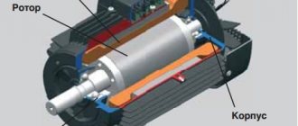
Squirrel-cage motors
Their rotor winding is a set of metal rods that connect two rings. The resulting figure is called a “squirrel wheel”. At the moment voltage is applied to the stator winding, a short circuit current arises in the rotor, the energy of which is spent on unwinding the shaft and is thereby extinguished. It has a slightly lower efficiency than synchronous machines, it does not exceed 80%.
After gaining speed, it has a very stable torque on the shaft and can withstand overloads well. The main advantages of such engines are their simplicity and reliability, thanks to which they are very widespread. Disadvantages: complexity of management.
To change the rotation speed, it is necessary to change the frequency of the supply voltage or the number of stator windings, which determines the number of poles of the electromagnet - the more there are, the lower it is. Also, electric motors with a squirrel-cage rotor are characterized by a large starting current that overloads the network, as well as a sharp increase in torque when power is connected, which can cause damage to the drive gearbox.
Wound rotor motors
The start-up of high-power squirrel-cage asynchronous motors (more than 30 kW) is associated with extreme overload of the supply network. To eliminate this phenomenon, machines with a wound rotor are used, the winding of which consists of three coils connected by a star. Their ends are connected by carbon brushes to three slip rings located on the motor axis.
How to find out your scheme
To correctly determine and calculate power, knowledge of several factors is required:
- Number of power phases;
- Method of connecting consumers.
For a single-phase connection, two wires are used:
A three-phase network is characterized by the presence of three or four conductors (connection with a grounded neutral). In this case, two different switching schemes are used:
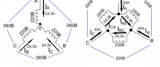
- "Triangle". Each load is connected to two adjacent ones. The voltage of each phase is supplied to the consumer connection points.
- "Star". All three consumers are connected at one point. The power phases are connected to the second ends. This is an isolated neutral circuit. In a circuit with a grounded neutral, the consumer connection point is connected to the neutral conductor.
How to switch windings?
Most three-phase electric motors are manufactured with an open circuit - they can be connected in either a star or a delta. It is enough to simply rearrange the jumpers on the BRNA distribution box (Distribution Block (Disconnection) Started Windings).
The standard jumper installation diagram for star and delta circuits is shown in the figure below.
But there are engines in which the distribution block has only 3 terminals. This means that the windings are already turned on according to one scheme or another and all that remains is to connect them to the network. For example, the engine whose nameplate is shown below can only be turned on with a “star”.
Healthy! If you wish and have some skills, you can disassemble the engine, understand the windings and connect them according to a different circuit. In this case, the motor will work perfectly.
Three-phase or single-phase connection
Depending on what type of connection is used, the power consumption is determined differently.
In a single-phase network, the energy consumed is calculated using the simplest formula:
where cosϕ is the power factor characterizing the phase shift between current and voltage in a reactive load.
The power of a 3-phase network is the sum of consumption for each phase separately. The power formula for 3-phase current is as follows:
Ptotal=Uа∙Iа∙cosϕа+ Ub∙Ib∙cosϕb+ Uc∙Ic∙cosϕc,
where U, I, cosϕ are voltage, current and power factor in each phase, respectively.
For your information. It can be seen that in the general case, a three-phase connection requires a larger number of metering devices.
Sometimes you can calculate energy consumption using a simplified version. With symmetrical consumption, for example, when connecting an asynchronous motor, the consumption currents are the same, and the formula takes the following form:
Where:
- Uph, Iph – phase voltage and current;
- Ul, Il – linear voltage and current.
Estimated calculation for no-load current and voltage
The power of an electric motor can also be determined by current or, as amateurs say, “by amperage.” But measuring the current when the machine is under load in order to find out its rated power is incorrect, because you have no way of knowing whether it is working under rated load, overloaded, or vice versa, underloaded. The stator current depends on the load. This means that you will not measure the rated current, but the current consumption at this moment.
So, you need to measure the no-load current, that is, when the engine is running without load. Before you measure anything, to get the correct data you need to let it run for some time, namely 0.5-1 hour for engines up to 100 kW and 1-2 hours for engines above 100 kW. After the measurement, use the table to find out the typical deviations of Ixx from Ir as a percentage and calculate the expected Ir.
Let's give an example, let's say you measured the current, it turned out to be 5 Amps. We estimate the engine power “by eye”, let’s say that it is quite large, and you assume that it is more than 5 kW. Moreover, this is a “three-thousander”, that is, its shaft rotates at a frequency of 3000 rpm. Then the measured no-load current is 40% (or 0.4) of the rated current. To find out the rated current, you need to divide Iхх by percentages from the table:
Then the total and active power can be determined by the formulas:
S=UI*1.73=380*12.5*1.73=8217 W=8.2 kW.
Let us assume that the cosФ of the motor is 0.85, and its efficiency is 0.8, then the active P1 is equal to:
P = Iav*Uav*1.73*cosf*efficiency=12.5*380*1.73*0.85*0.8=5.5 kW
True, there are no standard asynchronous three-phase motors with such parameters, the numbers were taken only as an example, but using the above method you can find out the motor power, knowing the current and voltage.
Characteristics of a three-phase system
A three-phase power supply system is characterized by several voltage and current values. It all depends on between which points of the circuit the measurements are made:
- between the phase wire and the neutral – phase voltage Uph;
- between individual phases – linear Ul.
The relationship between these parameters:
With symmetrical load distribution, the currents in all wires are equal. In a four-wire circuit (with a grounded zero), there is no current in the neutral conductor, so even if the zero is broken, the network continues to function normally.
In the case where the energy consumption differs between phases, some current flows in the neutral wire. A complete break in the neutral conductor causes a phase imbalance, so the voltage on the wires can change in the range from zero to linear.
The reactive nature of the load is taken into account by the power factor cosϕ. This value comes from the theory of complex numbers, which are used when it is necessary to calculate the parameters of alternating current circuits. In the case of an active load, cosϕ = 1, but the more reactive the consumers are, the more the coefficient decreases, showing how the real power decreases relative to the total.
Important! Therefore, to correctly calculate and reduce the load on generating equipment, power factor correctors are installed in reactive circuits. Circuits with a corrector bring the cosϕ coefficient closer to unity.
Specifics and features of three-phase networks
Three-phase electrical networks most efficiently transmit current through intermediate links, right up to the consumer. During the delivery process, energy losses are minimal.
The presence of a three-phase network in an apartment or private house is very easy to determine. To do this, you just need to look into the panel and count the number of wires. If there are 2 or 3 conductors, then the network is single-phase. There are two wires in it: phase and zero. If there is a ground, there may be a third wire. In three-phase networks there are two more wires due to the two additional phases. In the absence of grounding, there are only four of them, and in the presence of a grounding loop, there are five.
The same problem can be solved using an input circuit breaker. A certain number of wires are also supplied to it, connected to the appropriate terminals.
During the operation of a three-phase network, there is a high probability of uneven load distribution across individual phases. If only powerful equipment is connected to one of them, and ordinary household appliances are connected to the others, a situation called phase imbalance may arise. As a result of current and voltage asymmetry, individual consumers may fail. To avoid negative consequences, the load must be evenly planned at the design stage and the power of the three-phase network must be calculated.
A three-phase network, compared to a single-phase network, is distinguished by a large number of cables and wires, automatic devices and other devices. Specific three-phase equipment is connected to it. The total power will be exactly three times higher. The power value is calculated from current and voltage using formulas.
Example of calculating power indicators
The simplest example is the calculation of energy consumption by a symmetrical load. How much electricity will a three-phase asynchronous motor consume, connected to a network with a linear voltage of 380 V, and consuming a current of 10 A in each phase? Power factor cosϕ=0.76. Then the power consumption is:
More complex calculation of a household network:
- Phase voltage – 220 V;
- Line consumption – 10 A, 5 A, 2 A;
- The first two phases are connected to an active load (electric stove, kettle);
- The third is loaded with fluorescent lamps with cosϕ=0.5.
Ptotal=Uа∙Iа∙cosϕа+ Ub∙Ib∙cosϕb+ Uc∙Ic∙cosϕc=220∙10+220∙5+220∙2∙0.5=3520 VA.
Using an online calculation calculator, you can get rid of most errors and reduce calculation time. You just need to enter the data correctly according to the current parameters
Calculations of the main parameters of an asynchronous electric motor
Active power is spent to perform useful work and create heat. Denoted by the letter " P ", measured in W and calculated:
P = I * U * cos φ.
Reactive power is created by fluctuations in the energy of the electric field. It determines the ability of jet engine parts to store and emit electromagnetic energy. We are talking about the current that charges a capacitor or creates a magnetic field around the turns of a coil winding. Denoted by the letter " Q ", measured in Var and calculated:
Q=I*U*sinφ.
The total power " S " is represented by a mathematical combination according to the formula of the Pythagorean theorem: S*S = Q*Q + P*P . It is measured in V*A and is calculated:
S = P / cos φ = √(P 2 + Q 2 )=I*U.
The reactive power of a three-phase asynchronous motor can be represented as the sum of two components: inductive and capacitive.
The best representation of this quantity can be obtained in the form of a vector diagram, the inductive component is a positive coordinate on the Y axis, the capacitive component is negative. Obviously, these two values cancel each other out somewhat, making up a vector coordinate that will be either positive or negative. The smaller the angle between them, the closer the total power becomes to the active one.
The power factor cosφ for a three-phase asynchronous motor is 0.8–0.9. If it needs to be increased, then quite often capacitors are added to the motor circuits. The function of these capacitors is to provide a magnetizing current that reduces the amplitude of the reactive component. The higher the cosφ , the less energy the electric machine consumes.
Measuring power with a wattmeter
The power consumption of three-phase current is measured using wattmeters. This can be a special wattmeter for a 3-phase network, or a single-phase one connected according to a specific circuit. Modern electricity metering devices are often made using digital circuitry. Such designs are characterized by high measurement accuracy and greater capabilities for operating with input and output data.
Measurement options:
- Star connection with neutral conductor and symmetrical load - the measuring device is connected to one of the lines, the readings taken are multiplied by three.
- Asymmetrical current consumption in a star connection - three wattmeters in the circuit of each phase. The wattmeter readings are summed up;
- Any load and delta connection - two wattmeters connected in a circuit of any two loads. The wattmeter readings are also summed up.
In practice, they always try to make the load symmetrical. This, firstly, improves network parameters, and secondly, simplifies the accounting of electrical energy.
How to calculate a three-phase network
As an example, you can take certain production areas with installed equipment and, using these initial data, calculate the power of three-phase current.
Each machine uses an electric motor. Their total power Ру1 is 50 kW, taking into account active power. In addition, lighting fixtures with a total power (Ру2) of 3 kW are installed in the room. The symbol Ru indicates the amount of installed total power for specific groups of consumers. The equipment operates from a three-phase network with 4 wires and a rated voltage of 380 V.
In addition, the calculations take into account the demand coefficient Kc, operating in maximum load mode. It takes into account the highest number of inclusions of consumers in a given group. For electric motors, Kc1 is taken taking into account the magnitude of their load and is 0.35. For lighting devices, Kc2 is 0.9. All consumers are equalized by the average power factor cos φ = 0.75.
Calculations begin by determining the power load P1 = 0.35 x 50 = 17.5 kW. Next, the lighting load P2 = 0.9 x 3 = 2.7 kW is calculated. Thus, the value of the total design load will be P = P1 + P2 = 17.5 + 2.7 = 20.2 kW.
To determine and calculate the current, the formula I = (1000 x P)/(1.73 x Un x cos φ) is used, in which P is the estimated power of consumers, Un is the rated voltage of 380 volts, cos φ is the power factor.
Substituting the required values, we find the value of current strength and power: I = (1000 x 20.2)/(1.73 x 380 x 0.75) = 41 A. The result obtained makes it possible to find out whether the network can ensure normal operation of consumers .
What types of regulators are there?
There are two types of regulators available on the market today:
- on a variable resistor,
- electronic (stepping and moving).
They all have different ways of controlling the rotation speed and, therefore, the efficiency (electricity consumption) of each type is different. From this point of view, the classic regulator is the cheapest, but ineffective. Let's look at all three types.
Variable resistor regulator
In fact, this rheostat has a huge coil inside. By choosing low speed settings, we are essentially choosing higher circuit resistance. This results in lower current consumption (since the voltage is a fixed value). The devices are bulky in size and inexpensive in price.
Electronic regulator
Electronic are the newest types of regulators available on the market. They are much smaller in size than others. To reduce the voltage, they use capacitors instead of resistors, which, by adjusting the rotation speed, control the power signal. Unlike rheostats, they do not heat up and, therefore, save electricity when the motor operates at low speeds.
Regulators can save up to 40% at “1st” speed and about 30% at “2nd” speed compared to their resistor counterparts. There are electronic types of regulators:
- movable with smooth adjustment.
- step-by-step with a numbered action speed (usually from 1 to 5).
These devices provide a low level of motor movement distortion and, therefore, heat less. An option with the best technology and energy savings.