The invention of electricity brought humanity to a new frontier of development. Technological progress relied on two directions of movement using electricity. In one case, direct current was used, in the second - alternating current. The introduction of electricity sources and power consumers resulted in a hundred-year war between adherents of the two types of energy. In the end, those who promoted the idea of widespread use of its variable form won.
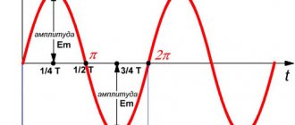
Sine wave of alternating electricity in the coordinate system
General concept of alternating current
Unlike electrons constantly moving in one direction, alternating current changes both direction and value several times per unit of time. Changes occur according to a harmonic law. If you observe a similar signal using an oscilloscope, you can see a picture in the form of a sine wave.
Relative to the ordinate axis OY, the current changes its direction from positive to negative and does this periodically. Therefore, its instantaneous value in the first position is considered positive, in the second - negative.
Important! Since alternating current is an algebraic quantity, we can talk about its sign of charge only for a specific instantaneous value, depending on the direction in which it flows at that moment.
Signal on the oscilloscope screen
Vector construction technique
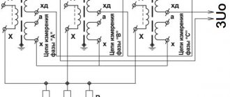
Technique for constructing vectors for two e. d.s. illustrated in Figure 10, a. On the left it shows sinusoids and it is clearly visible that e. d.s. e2 advances e1 by angle α. Right e. d.s. e1 is depicted by the vector E1M, which is located horizontally (that is, so that its projection onto the axis 1–1 is equal to the instantaneous value of e1 at point 0) and the arrow shows the direction of rotation 1. Then the angle α is plotted along this direction and the vector e is constructed. d.s. E2M.
Figure 10. Determining phase shift using a vector
The construction can be done differently. After constructing the vector E1M (which is located horizontally), a horizontal dashed line is drawn through the point of intersection of the sinusoid e2 with the vertical 2–2 (it cuts off the instantaneous emf e2 value corresponding to point 0). Then, with a radius of length E2M, a notch is made from point 0′ as from the center, after which the vector E2M is constructed. With this construction, the angle α is obtained automatically.
Examples of vector diagrams (that is, a set of vectors depicting sinusoidal quantities of the same frequency for different phase angles between e1 and e2) are given in Figure 10, b–f.
Pay special attention to Figure 10, e, which corresponds to Figure 10, d and shows that no matter how the vector diagram is located in the drawing, the phase shift does not change on it and this is very important.
Periodic alternating current
One that, while changing, manages to return to its original value at equal time intervals and at the same time goes through the entire cycle of its transformations, is called periodic. It can be traced on a sinusoid displayed on the oscilloscope screen.
Period and amplitude of sinusoidal oscillation
Resonance frequency: formula
It can be seen that at regular intervals the graph repeats without changes. These intervals are designated by the letter T and are called periods. The frequency with which a certain number of similar periods fits into a unit of time is the frequency of an alternating current.
It can be calculated using the AC frequency formula:
f = 1/T,
Where:
- f – frequency, Hz;
- T – period, s.
Frequency is equal to the number of cycles per second and has a unit of 1 hertz (Hz).
Attention! The SI unit of frequency is named after Heinrich Hertz. 1 hertz (Hz, Hz) = 1 s-1. Multiple and submultiple units, expressed by standard SI prefixes, are applicable to it.
Frequency standards
In order to ensure coordination of the operation of sources of alternating electricity, transmission systems, reception and operation of electrical consumers, frequency standards are applied. Frequency used in electrical engineering in some countries:
- 50 Hz – countries of the former USSR, the Baltic states, European countries, Australia, North Korea and others;
- 60 Hz is the standard adopted in the USA, Canada, the Dominican Republic, Taiwan, the Cayman Islands, Cuba, Costa Rica, South Korea and some other countries.
In Japan, both frequencies are used. Eastern regions (Tokyo, Sendai, Kawasaki) use 50 Hz. Western regions (Kyoto, Hiroshima, Nagoya, Okinawa) use a frequency of 60 Hz.
For your information. The railway infrastructure of Austria, Norway, Germany, Switzerland and Sweden still uses the 16.6 Hz frequency.
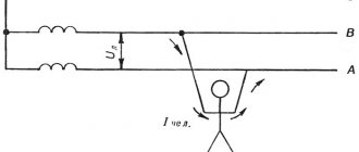
What happens in zero and phase when a wire breaks
What is power factor
If the electrical wire is broken, the corresponding outlet or the device connected to it ceases to function. It does not matter whether the phase or neutral wire is damaged. If the cable between the switchboards of an apartment building and one of its entrances breaks, all apartments connected to the entrance switchboard will lose electricity. If one of the phase wires breaks in a three-phase connection, the current that was in it before appears in the neutral wire, while nothing changes in the two remaining phases.
Method for detecting zero burnout
Alternating sinusoidal current
Rotation speed: formula
This is the current that changes periodically over time, and its changes obey the sinusoid law. This is the elementary movement of electric charges, therefore it cannot be further decomposed into simple currents.
The type of formula for such an alternating current is:
i = Im*sinωt,
Where:
- Im – amplitude;
- sinωt – phase of sinusoidal current, rad.
Here ω = const is called the angular frequency of alternating electricity, and the angle ωt is in direct time dependence.
Knowing the frequency f of the original current, you can calculate its angular frequency using the expression:
ω = 2πf = 2π/T.
Here 2π is the value of the central angle of the circle expressed in radians:
- T = 2 π radians = 3600;
- T/2 = π = 1800;
- T/4 = π/2 = 900.
If we express 1 rad in degrees, it will be equal to 57°17′.
Sinusoidal alternating motion of electrons
Polyphase AC
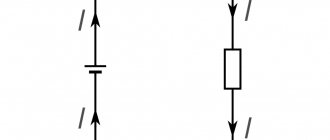
AC symbol
To start and operate many industrial devices and electrical equipment, not one phase, but several are required. In this regard, concepts such as two-phase and three-phase alternating currents are considered.
Three-phase current
This type of electricity is used in a three-phase system, which includes three single-phase circuits. The circuits have an EMF of variable nature of the same frequency. These emfs are phase shifted relative to each other by ϕ = Т/3 = 2π/3. Such a system is called three-phase current, and the circuit is called a phase.
The generation, conversion, delivery and consumption of alternating electric current mainly occurs through a three-phase power supply system.
Three-phase alternating current
Two-phase current
Back in 1888, Nikola Tesla described how a two-phase network could be used in practice, and proposed the design of a two-phase motor he developed. Such networks began to be used at the beginning of the 20th century. They consisted of two circuits.
There, the circuit voltages were shifted in phase by 900. Each phase included two wires; two-phase generators had two rotors, also structurally rotated at an angle of 900.
Important! Such networks made it possible to soft start two-phase electric motors from almost zero torque. While starting a single-phase asynchronous motor requires an additional starting winding or starting system.
Two-phase voltage graph and schematic drawing of a two-phase generator
INFOFIZ
Free vibrations can occur in electrical circuits, as well as in mechanical systems such as a spring load or a pendulum.
.
Electromagnetic oscillations
are periodic interrelated changes in charge, current and voltage.
Free
vibrations are those that occur without external influence due to the initially accumulated energy.
Forced
oscillations in a circuit under the influence of an external periodic electromotive force are called.
Free electromagnetic oscillations are periodically repeating changes in electromagnetic quantities ( q
- electric charge, I - current, U - potential difference) occurring without consuming energy from external sources.
The simplest electrical system capable of free oscillation is a series RLC circuit
or
oscillatory circuit
.
An oscillatory circuit
is a system consisting of a series-connected capacitor capacitor C , an inductor L and a conductor with resistance R.
Consider a closed oscillatory circuit consisting of inductance L and capacitance C.
To excite oscillations in this circuit, it is necessary to impart a certain charge to the capacitor from the source ε
.
When switch K
is in position 1, the capacitor is charged to voltage .
, the process of discharging the capacitor begins through resistor R
and inductor
L. Under certain conditions, this process can be oscillatory in nature.
Free electromagnetic oscillations can be observed on the oscilloscope screen.
As can be seen from the oscillation graph obtained on an oscilloscope, free electromagnetic oscillations are damped , i.e. their amplitude decreases over time. This happens because part of the electrical energy at the active resistance R is converted into internal energy. conductor (the conductor heats up when electric current passes through it).
Let's consider how oscillations occur in an oscillatory circuit and what energy changes occur. Let us first consider the case when there are no losses of electromagnetic energy in the circuit ( R
= 0).
If you charge the capacitor to voltage U0, then at the initial time t1=0 the amplitude values of voltage U0 and charge q0 = CU0 will be established on the plates of the capacitor.
The total energy W of the system is equal to the energy of the electric field Wel:
If the circuit is closed, current begins to flow. An emf appears in the circuit. self-induction
Due to self-induction in the coil, the capacitor is discharged not instantly, but gradually (since, according to Lenz’s rule, the resulting induced current with its magnetic field counteracts the change in the magnetic flux that caused it. That is, the magnetic field of the induced current does not allow the magnetic flux of the current to instantly increase in the circuit). In this case, the current increases gradually, reaching its maximum value I0 at time t2=T/4, and the charge on the capacitor becomes zero.
As the capacitor discharges, the energy of the electric field decreases, but at the same time the energy of the magnetic field increases. The total energy of the circuit after discharging the capacitor is equal to the energy of the magnetic field Wm:
At the next moment in time, the current flows in the same direction, decreasing to zero, which causes the capacitor to recharge. The current does not stop instantly after the capacitor is discharged due to self-induction (now the magnetic field of the induction current prevents the magnetic flux of the current in the circuit from instantly decreasing). At the moment of time t3=T/2, the charge of the capacitor is again maximum and equal to the initial charge q = q0, the voltage is also equal to the original U = U0, and the current in the circuit is zero I = 0.
Then the capacitor discharges again, the current flows through the inductance in the opposite direction. After a period of time T, the system returns to its initial state. The complete oscillation ends and the process repeats.
The graph of changes in charge and current strength during free electromagnetic oscillations in the circuit shows that fluctuations in current strength lag behind charge fluctuations by π/2.
At any moment of time the total energy is:
With free oscillations, a periodic transformation of electrical energy W
e, stored in the capacitor, into the magnetic energy
W
m of the coil and vice versa.
If there is no energy loss in the oscillatory circuit, then the total electromagnetic energy of the system remains constant.
Free electrical vibrations are similar to mechanical vibrations. The figure shows graphs of changes in charge q
(
t
) of the capacitor and the displacement
x
(
t
) of the load from the equilibrium position, as well as graphs of the current
I
(
t
) and the speed of the load υ (
t
) for one period of oscillation.
In the absence of damping, free oscillations in an electrical circuit are harmonic
, that is, they occur according to the law
q
(
t
) =
q
0cos(ω
t
+ φ0)
Parameters L
and
C
of the oscillatory circuit determine only the natural frequency of free oscillations and the oscillation period - Thompson’s formula
Amplitude q
0 and the initial phase φ0 are determined by
the initial conditions
, that is, the way in which the system was brought out of equilibrium.
For fluctuations in charge, voltage and current, the following formulas are obtained:
For capacitor:
q
(
t
) =
q
0cosω0
t
U
(
t
) =
U
0cosω0
t
For the inductor:
i
(
t
) =
I
0cos(ω0
t
+ π/2)
U
(
t
) =
U
0cos(ω0
t
+ π)
Let us recall the main characteristics of oscillatory motion:
q
0,
U
0,
I
0 -
amplitude - the modulus of the largest value of the oscillating quantity
T - period - the minimum period of time after which the process is completely repeated
ν - Frequency - number of oscillations per unit time
ω - Cyclic frequency - number of oscillations in 2 seconds
φ - oscillation phase - a quantity under the cosine (sine) sign and characterizing the state of the system at any time.
The amplitude of free oscillations decreases over time and they die out. In order for the oscillations not to die out, it is necessary to influence the oscillatory system with an external periodically changing force. Such oscillations are called forced.
Forced electrical oscillations are called alternating electric current.
An electric current that changes over time in direction and magnitude according to a harmonic law is called
alternating current
.
Let us consider an alternating electric current that changes with time according to a harmonic law. It represents forced oscillations of current in an electrical circuit, occurring with a frequency ω coinciding with the frequency forcing the emf.
Let us consider a closed loop (frame) of area S, placed in a uniform magnetic field, the induction of which is equal to B. The loop rotates uniformly around the axis OO' with an angular velocity ω.
The magnetic flux penetrating the circuit is determined by the formula Ф = BS cosΔφ, where Δφ is the angle between the normal vector n to the circuit plane and vector B. The frame rotates inside the magnet with a frequency v, and during time t it makes N = vt revolutions. Per revolution the frame rotates through an angle of 2π rad. The angle through which the frame rotates in time t: Δφ = 2π vt = ωt, then the change in magnetic flux ΔФ = BS cos Δφ = BS cos ωt.
In a closed circuit, an emf occurs. induction, which according to the law of electromagnetic induction is equal to the rate of change of magnetic flux.
Then we get the instantaneous emf value.
e = - Ф' = - (BS cos ωt)' = BSω sin ωt
Therefore, e.m.f. The induction that occurs in a closed circuit, when it rotates uniformly in a uniform magnetic field, changes over time according to the sine law. E.m.f. induction is maximum at sin ωt = 1, i.e. α = ωt = π/2
The quantity ε0 = ωBS is called the amplitude value of the emf. induction.
If such a circuit is closed to an external circuit, then a current will flow through the circuit, the strength and direction of which change. Such a frame rotating in a magnetic field is the simplest alternating current generator
.
In our country, alternating current with a frequency of 50 Hz is used (in the USA - 60 Hz). This current is produced by generators.
Electric current generators
are devices for converting various types of energy - mechanical, chemical, thermal, light, etc. - into electrical energy.
The operation of an alternator is based on the phenomenon of electromagnetic induction .
of generators available today
.
But they all consist of the same basic parts. This is, firstly, an electromagnet or permanent magnet that creates a magnetic field, and, secondly, a winding in which an alternating EMF
- electromotive force (in the considered generator model this is a rotating frame).
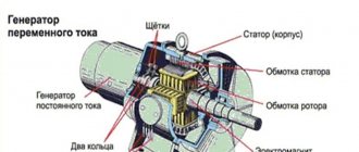
The stationary part of the generator is called stator , and the moving part is called rotor .
Since the EMF induced in series-connected turns add up, the amplitude of the induced EMF in the frame is proportional to the number of turns in it. It is also proportional to the amplitude of the alternating magnetic flux (Фm = BS) through each turn.
In the generator model shown in the figure, a wire frame rotates, which is the rotor. The magnetic field is created by a stationary permanent magnet. Of course, one could do the opposite: rotate the magnet and leave the frame motionless. Slip rings are attached to the ends of the rotor winding. Fixed plates - brushes - are pressed against the rings and connect the rotor winding with the external circuit.
Alternator model
Industrial generators are much larger in size; to increase the voltage removed from the generator terminals, not one, but many turns are wound on the frames. In all industrial alternating current generators, the coils in which alternating current is induced are mounted stationary, and the magnetic system rotates. If the rotor is rotated with the help of an external force, then the magnetic field created by it will rotate along with the rotor, and an emf will be induced in the stator conductors.
The operating principle of an alternating current generator is as follows. To obtain a large magnetic flux, generators use a special magnetic system consisting of two cores made of electrical steel. The windings that create the magnetic field are placed in the slots of one of the cores, and the windings in which the EMF is induced are in the slots of the other. One of the cores (usually internal) together with its winding rotates around a horizontal or vertical axis. That's why it's called a rotor. The stationary core with its winding is called a stator. The gap between the stator and rotor cores is made as small as possible to increase the flux of magnetic induction.
In large industrial generators, it is the electromagnet, which is the rotor, that rotates, while the windings in which the EMF is induced are placed in the stator slots and remain stationary. The fact is that current must be supplied to the rotor or removed from the rotor winding to an external circuit using sliding contacts. To do this, the rotor is equipped with slip rings attached to the ends of its winding.
Block diagram of an alternating current generator.
Fixed plates - brushes - are pressed against the rings and connect the rotor winding with the external circuit. The current strength in the windings of the electromagnet that creates the magnetic field is significantly less than the current supplied by the generator to the external circuit. Therefore, it is more convenient to remove the generated current from the stationary windings, and through the sliding contacts to supply a relatively weak current to the rotating electromagnet. This current is generated by a separate direct current generator (exciter), located on the left side of the shaft (Currently, direct current is most often supplied to the rotor winding from the stator winding of the same generator through a rectifier).
In low-power generators, the magnetic field is created by a rotating permanent magnet. In this case, rings and brushes are not needed at all.
The appearance of EMF in stationary stator windings is explained by the appearance of a vortex electric field in them, generated by a change in the magnetic flux when the rotor rotates. A modern electric current generator is an impressive structure made of copper wires, insulating materials and steel structures. With dimensions of several meters, the most important parts of the generators are manufactured with millimeter precision. Nowhere in nature is there such a combination of moving parts that can generate electrical energy so continuously and economically.
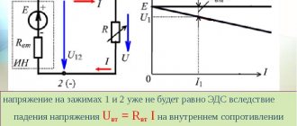
In an alternating current circuit, the power will also change its value. As a rule, we need to know the average power. To calculate it, it is convenient to use the effective values of current and voltage.
The AC voltmeter and ammeter always show RMS values.
The instantaneous value of the alternating current flowing through the active resistance R is determined by Ohm's law:
where I 0
= ε 0 / R
–
amplitude value of the current
.
The current is in phase with the emf.
The value equal to the square root of the average value of the square of the instantaneous current is called
the effective value of the alternating current.
Denoted by I.
AC voltage rms value
is determined similarly to the effective current value:
The effective
(effective) value of the alternating current
and
the effective (effective) value of the voltage are equal to the voltage and strength of the direct current, which releases in the conductor the same amount of heat as the alternating current for the same time.
Electromagnetic field and electromagnetic waves.
In the world around us there are objects that a person does not perceive with the help of his senses. To measure the characteristics of these objects, a person can only use special technical devices. Such objects are electric and magnetic fields
.
Having studied the phenomenon of electromagnetic induction, Faraday
came to the conclusion that the vortex electric field arises when
the magnetic field
. A time-varying magnetic field can be created at a given point in space by moving a magnet towards it or changing the current strength in a wire located next to this point.
In 1864
English physicist
James Clerk Maxwell
analyzed all the laws of electrodynamics known at that time and made an attempt to apply them to time-varying electric and magnetic fields.
He drew attention to the asymmetry of the relationship between electrical and magnetic phenomena. Maxwell introduced the concept of a vortex electric field into physics.
Maxwell proposed a new interpretation of the law of electromagnetic induction, discovered by Faraday in 1831:
Any change in the magnetic field generates a vortex electric field in the surrounding space, the lines of force of which are closed.
An alternating magnetic field generates an electric field with closed lines of force (tension lines cover the lines of magnetic induction (Fig. 1, a). The faster the magnetic induction changes, the greater the electric field strength. As the magnetic induction increases, the direction of the intensity forms a left screw
with the direction of the vector.
So, a magnetic field generates an electric one. Maxwell admitted that an alternating electric field, in turn, generates a magnetic field. In all cases where an electric field changes over time, it generates a magnetic field
.
The lines of magnetic induction of this field cover the lines of electric field strength (Fig. 1, b) just as the lines of electric field intensity cover the lines of induction of an alternating magnetic field. But only when the electric field strength increases, the direction of the induction vector of the emerging magnetic field forms right
screw with the direction of the vector.
So:
A time-varying electric field generates a magnetic field in the surrounding space.
Maxwell's hypothesis was only a theoretical assumption that did not have experimental confirmation, but on its basis Maxwell managed to write down a system of equations describing the mutual transformations of electric and magnetic fields, that is, a system of
electromagnetic field
.
After the discovery of the relationship between electric and magnetic fields, it became clear that these fields do not exist separately, independently of one another
. It is impossible to create an alternating magnetic field without simultaneously creating an electric field in space. Conversely, an alternating electric field cannot exist without a magnetic field.
Variable electric and magnetic fields exist simultaneously and form a single electromagnetic field
.
An electromagnetic field
is a special form of matter - a combination of electric and magnetic fields - with the help of which electromagnetic interaction is carried out.
Materiality of the electromagnetic field
:
- 1.
You can register. - 2.
It exists regardless of our will and desire. - 3.
Has a high but finite speed.
While developing the theory of the electromagnetic field, D. Maxwell in the 60s of the 19th century theoretically substantiated the possibility of the existence of electromagnetic waves and even calculated the speed of their propagation. It coincided with the speed of light v=c=3*108m/s. This gave Maxwell reason to conclude: light is a type of electromagnetic wave.
Around a stationary charge there is only an electric field. An electromagnetic field appears around a charge moving at a constant speed. With the accelerated movement of a charge, an electromagnetic wave is emitted, which propagates in space at a finite speed.
An electromagnetic field varying in time and propagating in space forms
an electromagnetic wave.
Electromagnetic waves are transverse
– vectors and are perpendicular to each other and lie in a plane perpendicular to the direction of wave propagation.
In an electromagnetic wave, mutual transformations of electric and magnetic fields occur.
Electromagnetic waves propagate in matter at a finite speed
Speed of electromagnetic waves in vacuum (ε = μ = 1): 300000 km/s = 3·108 m/s
The main condition for the occurrence of an electromagnetic wave
is the accelerated movement of electric charges.
Radio communication is a type of wireless communication that uses radio waves propagated in space as a signal.
The principles of radio communication are far from new. During this time, radio equipment has gone from the first Morse code signal transmitters to satellite communication systems. The radio air was filled with music from radio stations, signals from distant galaxies and our conversations. However, since then the main thing has not changed - radio waves.
G. Hertz experimentally proved the existence of electromagnetic waves in 1888.
A. S. Popov repeated these experiments and in April 1895 created the first receiver.
May 7, 1895 demonstration of the device at a meeting of the Russian Physico-Chemical Society. Range - 250 m; 1899 - 20 km; 1901 - 150 km.
Popov was the first to use a coherer and a receiving antenna.
The principle of radiotelephone communication.
The principle of radio communication is based on transmitting a signal from a transmitting device containing a transmitter and a transmitting antenna, by moving radio waves in open space, to a receiving device containing a receiving antenna and a radio receiver.
The transmitter microphone, under the influence of sound vibrations, produces a weak low-frequency electric current. This signal enters a low frequency amplifier (LF). The ULF signal enters the modulator. The high frequency generator (HFG) produces continuous high frequency oscillations (HF), which also enter the modulator, where they are amplitude modulated by low frequency oscillations and enter the antenna. The antenna emits electromagnetic waves into the surrounding space, the amplitude of which is also modulated at low frequency. The HHF frequency is the carrier frequency, and it determines the frequency (and wave) of the transmitting station. Harmonic oscillations with a carrier frequency belonging to any radio frequency range are modulated in accordance with the transmitted message. Modulated radio frequency oscillations constitute a radio signal, and modulated electromagnetic waves constitute a radio wave .
Moving freely, radio waves reach the receiving antenna and excite electrical vibrations in it, which then enter the radio receiver. In the receiver antenna, radio waves (in reality there are many transmitters) excite alternating induction emfs of different frequencies. To select the frequency of the desired radio station, an input oscillating circuit is used, which may have a variable capacitor or a coil with variable inductance. In any case, a change in capacitance or inductance leads to a change in the natural frequency of the input circuit and, at the moment when this frequency coincides with the carrier frequency of the radio station, resonance is observed. This effect allows you to highlight the signal of a particular radio station among others. However, the signal remains weak in the fall and is amplified by the high frequency amplifier (UHF) of the receiver. The received radio signal is demodulated after amplification. The detector selects one half of the amplitude-modulated signal, the filter smoothes out the ripples, turning it into a low-frequency signal. The ULF amplifies the low-frequency signal, and the loudspeaker converts the amplified electrical signal into sound vibrations. A signal is released that is similar to the signal with which the oscillations in the radio transmitter were modulated. The signal is converted using an appropriate playback device into a message similar to the original one.
Block diagram of a radio transmitter and radio receiver.
1. Master oscillator
(high frequency generator) produces harmonic oscillations of high HF frequency (carrier frequency more than 100 thousand Hz).
2. Microphone
converts mechanical sound vibrations into electrical vibrations of the same frequency.
3. Modulator
changes (modulates) high-frequency oscillations in frequency or amplitude using electrical oscillations of low LF frequencies.
UHF high and low frequency amplifiers
and
ULF
amplify the power of high-frequency and sound (low-frequency) electrical vibrations.
5. Transmitting antenna
emits modulated electromagnetic waves.
6. Receiving antenna
receives electromagnetic waves. An electromagnetic wave that reaches the receiving antenna induces in it an alternating current of the same frequency at which the transmitter operates.
7. UHF.
8. Detector
selects low-frequency oscillations from modulated high-frequency oscillations.
9. ULF.
10. Speaker
converts electromagnetic vibrations into mechanical sound vibrations.
Amplitude modulation
Changing the amplitude of vibrations of a high (carrier) frequency by vibrations of a low (sound) frequency is called
amplitude modulation
.
To obtain amplitude-modulated electromagnetic oscillations, a transformer coil is connected in series with the oscillating circuit to the transistor generator circuit. Audio frequency voltage is applied to the primary winding of the transformer. An EMF of the same frequency is induced on the secondary winding of the transformer and is added to the constant voltage of the current source. A change in the voltage between the emitter and the collector of the transistor leads to a change in the sound frequency, the amplitude of high-frequency current oscillations in the oscillatory circuit of the generator. As a result, the amplitude of oscillations in the generator circuit will change in time with the change in the voltage of the low-frequency signal on the transistor. When the amplitude of the LF signal changes, the depth of the modulation changes.
Detection (demodulation)
The separation of low-frequency oscillations from modulated high-frequency oscillations is called detection (demodulation).
Detection is carried out by a device containing an element with one-way conductivity: a vacuum or semiconductor diode - a detector.
The current-voltage characteristic of the diode shows that the current in the circuit flows predominantly in one direction, being a pulsating current.
This current is smoothed using a filter.
When a diode passes current, part of it passes through the load, and the other part is branched off to the capacitor.
If the diode is blocked, then the capacitor is partially discharged through the load. Current ripple is reduced.
An audio frequency current flows through the load, and the oscillation shape reproduces the shape of a low-frequency signal.
A television. Basic principles.
A television
— a communication system for broadcasting and receiving moving images and sound at a distance.
Television is based on the principle of sequential transmission of image elements using a radio signal or wires. The image is decomposed into elements using a Nipkow disk, cathode ray tube or semiconductor matrix. The number of image elements is selected in accordance with the radio channel bandwidth and physiological criteria. To narrow the bandwidth of transmitted frequencies and reduce the noticeability of flickering on the TV screen, interlaced scanning is used. It also allows you to increase the smoothness of motion transmission.
The television circuit basically coincides with the radio broadcasting circuit. The difference is that in the transmitter the oscillations are modulated not only by audio signals, but also by image signals. Optical signals in the transmitting camera are converted into electrical signals. A modulated electromagnetic wave carries information over long distances. In a television receiver, the high frequency signal is divided into three signals: the image signal, the audio signal and the control signal.
After amplification, these signals enter their blocks and are used for their intended purpose.
The television channel in general includes the following devices:
1. Television transmission camera. Serves to convert the image obtained using a lens on the target of the transmitting tube or semiconductor matrix into a television video signal. To reproduce motion, they use the principle of cinema: the image of a moving object (frame) is transmitted dozens of times per second (in television 50 times). The frame image is converted into electrical signals using an iconoscope.
An iconoscope is a transmitting vacuum electron tube that converts the image of a frame into a series of electrical signals.
An image of an object is projected onto the iconoscope screen using an optical system (lens). The same signal is received in a television receiver, where the signal is converted into a visible image on the kinescope screen.
2. Telecine projector. Converts the image and sound on film into a television signal, and allows you to show movies on television.
3. VCR. Records and at the right time plays back the video signal generated by the transmitting camera or telecine projector.
4. Video mixer. Allows you to switch between multiple image sources: cameras, VCRs and others.
5. Transmitter . The high frequency carrier signal is modulated by a television signal and transmitted by radio or wire.
6. Receiver - TV. With the help of synchronization pulses contained in the video signal, the television image is reproduced on the receiver screen (kinescope, LCD display, plasma panel).
A kinescope is a receiving vacuum electron tube that converts electrical signals into a visible image.
In addition, to create a television broadcast, an audio path similar to the radio transmission path is used. Sound is transmitted at a separate frequency, usually using frequency modulation, using technology similar to FM radio stations. In digital television, audio, often multi-channel, is transmitted in a common data stream with the image.
Television radio signals are transmitted in the ultrashort wave range, i.e. within the direct line of sight of the antenna. Repeaters (TV transmitters) are used to transmit signals over long distances. The area of reliable television reception is increasing due to the use of relay satellites.
The tower of the Ostankino television center, 540 m high, provides reception within a radius of 120 km.
Applications of radio communication
In our technological age, radio communications have deeply penetrated everyday life.
Mobile connection. The vast majority of modern people cannot imagine their lives without a mobile phone. But rarely do any of them realize that a mobile phone is a device that combines the functions of a receiver and a transmitter, and mobile communications are carried out using the same ordinary radio waves.
Radiotelephone communication. Where walkie-talkies are used - various transceiver devices (police, ambulance, Ministry of Emergency Situations, etc.), communication is also carried out using radio waves.
Reception of television signals using antennas installed on the roofs of houses is gradually becoming a thing of the past. However, the same radio waves carry the image
Satellite television, telephone communications, the Internet - all this exists thanks to radio waves that are emitted by the transmitter, relayed by the satellite and reach the receiver.
Wireless mice, keyboards, and headsets also contain miniature radio wave transceivers.
Biuetooch, Wi-Fi, wireless computer networks are also transmitters and receivers of radio waves.
Various radio-controlled models necessarily have a control unit (transmitter) and a receiver in the model itself.
GPS, GLONASS - global positioning systems, with the help of which you can determine not only your location, but also much more - they also work in the radio wave range.
Radar . A.S. Back in 1900, Popov discovered the reflection of electromagnetic waves from ships and pointed out the possibility of using this effect in radar. It was later discovered that almost all substances reflect radio waves. The result of reflection depends not only on the type of substance, but also on the wavelength. The essence of radar is as follows. The transmitter generates a high-frequency pulse and, using a special parabolic antenna, sends it in the direction of an object, for example, an airplane. A radio wave, reaching an object, is reflected from it in all directions. Part of the reflected wave, the energy of which is very small, is captured by the receiving parabolic antenna. Knowing the time t between the moment of emission and the moment of signal reception, it is easy to calculate R the distance to the object: R=ct/2, where c is the speed of propagation of the radio wave.
Of course, this is the most primitive radar scheme. Currently, the analysis of the received signal is carried out by a specialized computer, which determines not only the distance, but also the speed, type of object, automatically analyzes “friend or foe”, compares it with a database and displays its tactical and technical characteristics, etc. There are mobile radar systems and powerful stationary systems that simultaneously track hundreds of objects near the Earth's surface and in space over half of Russia's territory.
In radio astronomy, radar methods are used to determine distances to celestial bodies and track the movement of astronomical objects.
In astronautics, they monitor the position and movement of various spacecraft.
A map of the surface of Venus, hidden by a thick cloud cover, was compiled using radar.
Effective value of sinusoidal current
Effective value refers to its effectiveness. It is equal to the value of direct current that will do the same work as alternating current in one period of time. By work here we mean its thermal or electrodynamic orientation. It is most convenient to use the rms value of alternating electricity.
Then the effective value for the sinusoidal current is determined by the formula:
I = * Im ≈ 0.707 * Im,
where Im is the magnitude of the current amplitude.
RMS current value
Measuring instruments
To determine the intensity of oscillations, an oscilloscope is used, where you can see the frequency and shape of the signal. There are also special devices - frequency meters. They use the following methods for determining the parameter:
- overcharge of the capacitor - the average value of the current is proportional to its intensity and is measured by a magnetoelectric ammeter with a scale in Hertz;
- discrete counting - recording pulses of the required frequency for a certain period, obtaining data of sufficient accuracy: the error is within 2%, this is a good indicator for domestic use of the device;
- the resonant method is based on the electrical phenomenon of the same name that occurs in a circuit with tuned elements; frequency - more than 50 Hz, determined by the scale of the adjusting mechanism.
Another well-known method is used in oscilloscopes and is based on mixing and comparing a reference parameter with the measured frequency. Due to the overlap, beats occur, and when aligned, a certain figure is established on the screen. The required characteristic is calculated according to a fixed schedule using mathematical formulas.
AC generation
In addition to standard generators, inverters and phase splitters are used to produce alternating current.
Inverter
This is a device with the help of which direct current is converted into alternating current. During this process, the output voltage also changes. The device circuit is an electronic generator of a sinusoidal pulse voltage of a periodic nature. There are options for inverters that operate with a discrete signal. Inverters are used for autonomous power supply of equipment from constant voltage batteries.
Inverter 12/220 V, power 1500 W
Phase splitter
Another way to get multiple phases from a signal is to split it into several phases. This is done using a phase splitter. Forced processing of digital or analog signals is used both in radio electronics and power electrical engineering.
To supply power to three-phase asynchronous motors, a phase splitter based on them is used. To do this, the windings of a three-phase motor are connected not by a star, but in a different way. Two coils are connected to each other in series, the third is connected to the midpoint of the second winding. The motor is started as a single-phase one, after acceleration, an EMF is induced in its third winding.
Interesting. In the case of phase splitting using this method, the phase shift between windings 2 and 3 is not 1200, as it should ideally be, but 900.
Options for determining phase/neutral conductors
So, a situation has come when it is necessary, for example, to connect a new outlet. But it is not at all clear which of the wires is phase and which is neutral. There are several ways to quickly solve the problem - this can be done both with the use of special devices and without them.
Color coloring of wires as a main guide
This is the easiest and fastest way. To correctly classify zero and phase, you should know which wire color belongs to what. You will first need to study information about where the current standards for a particular country are clearly stated.
This method is very relevant in any new buildings, since now all electrical wiring is laid by specialists who carry out their work in accordance with all the requirements of established standards. For example, in Russia back in 2004, the “IEC60446” standard was adopted, which clearly defines the procedure for separating cables by color, namely:
- a yellow-green wire began to be designated as a protective zero;
- the working zero began to be called the blue/blue-white wire;
- phase - wires of other colors (for example, black, red, brown and others).
This designation is currently relevant.
If the wiring is already quite old or its installation was carried out by non-professional specialists, it would still be more correct to use other methods of determination.
An indicator screwdriver is an indispensable device
This tool is an integral part of the home electrician's kit. It is used both when performing electrical installation work, and when installing lighting fixtures indoors, or even in the process of simply replacing light bulbs.
The principle of its operation is the passage of capacitive current through the body of the screwdriver through the operator’s body.
Screwdriver elements:
- housing made of dielectric material;
- a metal tip in the shape of a flat screwdriver, which is applied to the wires when checking;
- neon indicator - a light bulb signaling the phase potential;
- current limiter - a resistor that reduces the current to a minimum value and acts as a protective mechanism: it protects a person from electric shock, and the device itself from failure;
- a contact metal pad that creates a closed circuit through a person to the ground.
The method of work is so simple that anyone, even a beginner, can cope with it. The indicator screwdriver works as follows. When the tip touches the phase contact (colored wire), the electrical circuit is closed - the neon lamp should light up. That is, a “message” is received about the presence of resistance, therefore, this cable is a phase. At the same time, it should not light up either at ground or at zero. If this happens, we can say with confidence that there are errors in the wiring diagram.
Working with an indicator screwdriver during daylight hours will require some care - during the day the glow of the lamp is difficult to see, so you will have to look closely.
When working with such devices, you need to be extremely careful - do not touch exposed areas of conductors and indicator terminals that are under voltage.
On a note! Professional electricians use more expensive multifunctional indicators, the glow of which is controlled by a transistor circuit powered by built-in 3 V batteries. Another characteristic difference from simple analogues is the absence of a contact pad that needs to be touched when taking measurements.
The devices, in addition to their direct purpose - checking the phase wire - also perform a number of other auxiliary tasks: determining the polarity of DC voltage sources, the location of an electrical circuit break, and so on.
Multimeter - a reliable assistant
To calculate the phase using a tester, you need to switch it to the “voltmeter” mode and measure the voltage between all paired cable terminals. The connection of the probes to the protective zero and ground should indicate the absence of voltage. The voltage between the phase and any other wires should be 220 V.
Ways to identify wires:
So, in the first case, the voltmeter deviates from zero o. In another picture it shows the absence of voltage between zero and ground. And on the third, the voltmeter between the phase and the ground shows “0 V” since the conductor is not yet connected to the ground. The third case is rather an exception to the rule. This is possible, for example, in cases where the old cables of the building are at the stage of reconstruction. In a normal working electrical wiring system, the voltmeter should also show 220 V.
Using an incandescent lamp
Before starting work, you will need to assemble the testing device. It will consist of an ordinary light bulb, socket and wires. The lamp is screwed into the socket, and conductors are attached to the terminals of the socket. One of the wires will need to be grounded, for example, connected to a heating battery.
The essence of the method is to alternately apply a second (free) conductor to all tested conductors. If the light flashes, a phase wire has been found.
The method allows you to determine approximately the presence of a phase cable among the others. The lamp signal accurately indicates that among these conductors some are phase and some are neutral. If the lamp does not light, then there is no phase cable among the cables. But it may happen that there is precisely zero.
Therefore, to a greater extent, this method is appropriate for determining the functionality of electrical wiring and correct installation.
AC networks
Based on their purpose and application, these networks can be classified as follows:
- general systems: power supply for industrial, transport, agricultural and domestic facilities;
- autonomous networks: supplying mobile and stationary autonomous entities.
General three-phase alternating current networks are built according to a four-wire circuit, where three wires are “phase” and the fourth is “zero”. Transformer substations are built according to a scheme with a solidly grounded neutral. Long-distance transmission is carried out at high voltage, which is then reduced at substations to a voltage of 0.4 kV and distributed to consumers.
Household objects are connected using a single-phase circuit. In this case, two wires are required: “phase” and “neutral”.
Household electrical wiring device
Rotor - what is it?
A standard electrical wiring diagram contains the following elements:
- multi-tariff electricity meter;
- automatic switch with a rated current of 25 A;
- a shutdown mechanism that protects against short circuits and network overloads;
- differential circuit breaker with an operating threshold of 30 mA (leakage current), it protects sockets;
- cabinet for installation with busbars (neutral and grounding) and boards for installing switches;
- several lighting machines with a rated current of 10 A;
- cables with distribution boxes leading to sockets and devices that illuminate the premises.
Often apartment owners are interested in whether a phase is plus or minus, and what is the difference between zero and ground. Since the electrical phase has a variable potential, its indicator in the phase wire becomes either positive or negative. Therefore, it would be incorrect to say that phase is a minus (or a plus) - these concepts lie on different planes.
Now let's talk about how zero differs from ground. The difference is that current passes through the neutral wire and is opened by automatic devices (for example, the input wire). To ground in an apartment building, you need to connect to a conductor located in the riser, designed specifically for this purpose. It is strictly prohibited to use any other place, including the panel housing, for grounding - this can cause serious problems for the health of residents.
Household electrical wiring device
Relationship between frequency and operation of electrical equipment
Current frequency is one of the parameters of electricity that affects the stable operation of electrical installations and equipment. When supplying energy to the consumer, this parameter is strictly controlled, just like voltage.
The thread of relationship is expressed by the formula for the nominal number of revolutions per minute for rotating machines. Efficiency (coefficient of performance) is inherent in the very design of the units. It is maximum at:
n = 60f/p,
Where:
- n – number of rpm;
- f – frequency;
- p – number of pairs of poles.
The number of revolutions of the generator turbine is directly related to the frequency of the generated alternating current; the resulting frequency is responsible for the optimal rotation mode of the consumer's electric motor. When the frequency in the network decreases, the machine speed is reduced automatically. The shaft is overloaded and the engine suffers.
At the same time, the production line into which it transfers rotational energy also undergoes changes in operation:
- the speed of the conveyor changes, which entails a failure of the technological process and ultimately defects;
- the power and rotation speed of pumps and fans are reduced, which leads to unstable operation of the systems in which they are installed;
- a 1% decrease in frequency in the power system leads to a drop in the total power at the load to 2%.
Frequency meters are used to monitor this important electrical parameter.
Attention! A decrease in frequency by 10-15% causes the productivity of mechanisms even at the power plant itself to drop to zero. At a current frequency in the network of 50 Hz (the critical value is 45 Hz), an avalanche decline occurs.
Electrical network structure, main elements
What is potential in electricity
The electrical network is the connecting link between generators and recipients of electrical energy. The energy sources in the internal networks of industrial and residential premises are ASUs (input distribution devices). Cables are connected to them via switches and fuses, powering electrical equipment or a group of receivers through busbars and switching boxes.
Structure of the electrical network of an apartment building
High frequency currents
HDTV – this is their abbreviation; they are used for melting metals and hardening the surface of metal products. HDTV are currents with a frequency of more than 10 kHz. Induction furnaces use HDTV by placing a conductor inside a winding through which the HDTV is passed. Under their influence, eddy currents arising in the conductor heat it up. By adjusting the strength of the HDTV, the temperature and heating rate are controlled.
Interesting. The metal to be melted can be suspended in a vacuum using a magnetic field. It does not require a crucible (a special ladle for heating). This is how very pure substances are obtained.
Advantages of using HDTV in different cases:
- rapid heating during forging and rolling of metal;
- optimal temperature conditions for soldering or welding parts;
- melt even very refractory alloys;
- cooking in microwave ovens;
- Darsonvalization in medicine.
HDTV is obtained using installations that include an oscillating circuit or electric machine generators. The stator and rotor of the generators have teeth on the sides facing each other. Their mutual movement generates a pulsation of the magnetic field. The greater the product of the number of rotor teeth and its rotation frequency, the greater the output frequency.
Pulsation period and frequency
The frequency of alternating current may have another name - ripple. The pulsation period is the time of a single pulsation.
Cycle intensity
For an electrical network with a frequency of 50 Hz, the pulsation period will be:
T = 1/50 = 0.02 s.
If necessary, knowing this dependence, you can calculate the frequency from the cycle time.
The danger of multi-frequency charges
Both direct and alternating current at certain values pose a danger to humans. Up to 500 V the difference in safety is in the ratio 1:3 (42 V DC to 120 V AC).
At values above 500 V, this ratio levels out, with constant electricity causing burns and electrolysis of the skin, while changing electricity causes convulsions, fibrillation and death. Here the pulsation frequency is of great importance. The most dangerous frequency range is from 40 to 60 Hz. Further, with increasing frequency, the risk of damage decreases.
Effect of frequency on threshold current
The frequency of alternating electricity is an important parameter. It affects not only the operation of consumer electrical installations, but also the human body. By changing the frequency of electrical oscillations, it is possible to change technological processes in production and the quality of the generated energy.