The three-phase voltage system is symmetrical in normal operation. But as soon as a short circuit occurs, the symmetry is broken. For the convenience of recognizing types of short circuits and carrying out calculations, the method of symmetrical components is used. According to it, any three-phase system from the moment of short circuit can, for convenience of calculations, be represented as the sum of the voltages of three symmetrical systems:
- direct sequence;
- reverse sequence;
- zero sequence.
All of them are imaginary quantities that do not exist in reality. But with the help of some tricks they can be made really tangible and put into practice.
Devices that extract voltage of the desired sequence from a three-phase voltage system are called filters. Let's consider one of these devices, used in practice to detect ground faults.
Purpose of additional VT windings
A feature of the zero-sequence voltage (3Uo) is the fact that it does not appear as a result of phase-to-phase faults, but is only a consequence of a ground fault. Moreover, it does not matter where the short circuit occurs: in an electrical installation with an insulated or solidly grounded neutral.
The filter for isolating this value is the special windings of voltage transformers (VT).
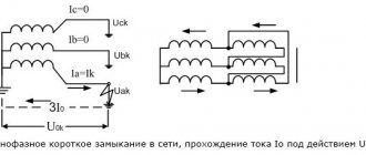
This process occurs differently depending on the design of the transformers. If three identical VTs are used, each of them has a special winding, the terminals of which are designated by the letters “Hell” and “Xd”. These windings are connected to each other in series, with obligatory observance of the direction. The wire from the “Hd” terminal of phase “A” goes to the “Ad” terminal of phase “B” and so on. This connection scheme is called an open delta.
As a result, on the remaining open terminals “Ad” of the first phase and “Xd” of the last, in any case of damage in the network associated with a ground fault, 3Uo will appear. You can measure it and also use it for alarm operation by connecting it to the winding of a voltage relay. It can also be used to operate protections, but more on that a little later.
Voltage transformers that combine the windings of three phases in one housing do not require external connections for the 3Uo filter. Everything has already been done in advance, inside the transformer housing.
If in the previous case, the release of 3Uo occurs by sequential addition of voltage vectors due to switching of conductors, then inside a three-phase VT this occurs due to the addition of magnetic fluxes in the core. Therefore, depending on its shape, the internal connection diagram of the Ad-Hd windings may differ.
But this does not change the essence: as a result, on the case, next to the terminals of the main windings used for accounting, measurement and protection, terminals from the combined additional winding 3Uo appear. It is designated in exactly the same way as on single-phase VTs.
Watch an interesting video about TZNP below:
Posts 1 to 20 of 23
1 Topic from Sigmund Freud 2015-05-20 14:49:07
Topic: Negative sequence voltage
Good afternoon How to calculate negative sequence voltage values Uab and Ubc?
2 Reply from retriever 2015-05-20 14:51:50 (2015-05-20 14:54:47 edited by retriever)
Re: Negative sequence voltage
How to calculate negative sequence voltage values Uab and Ubc?
Can you rephrase the question? It’s generally not clear what MB is talking about, can you calculate it using the values of Uab and Ubc?
3 Reply from Sigmund Freud 2015-05-20 14:55:37
Re: Negative sequence voltage
Can you rephrase the question? It’s not at all clear what we’re talking about
Knowing the linear voltages Uab and Ubc, how to find U2? If you know, let's say Ua Ub and Uc, finding U2 is not a problem if the classic formula is: U2=1/3(Ua+k1*Ub+k2*Uc).
4 Reply from Borisych 2015-05-20 15:00:28
Re: Negative sequence voltage
The question is not entirely clear. Is this what we're talking about? Uа-с=3U2ф=1.73U2л
5 Reply from Sigmund Freud 2015-05-20 15:03:39
Re: Negative sequence voltage
The question is not entirely clear. Is this what we're talking about? Uа-с=3U2ф=1.73U2л
No. We need a ready-made formula, according to which, knowing the value of lin. eg Uab and Ubc the negative sequence voltages could be found.
6 Reply from Borisych 2015-05-20 15:11:24
Re: Negative sequence voltage
From the analysis of the vector diagram of the FNOS it follows that the voltage at the output of the FNOS is Umn=1.5·UAB2=1.5·UBC2.
Added: 05/20/2015 15:40:33
This is when feeding A-C-B
Added: 05/20/2015 15:41:24
Somehow the pictures are not inserted. I wanted to put in a vector FNOP.
7 Reply from GreenAlien 2015-05-20 17:30:29
Re: Negative sequence voltage
If we are talking about complex quantities, then the derivation of the formula is quite simple (but you’d better check it with me): U2=(Ua+a^2*Ub+a*Uc)/3=(Ua-Ub+Ub+a^2* Ub+a*Ub-a*Ub+a*Uc)/3=(Uab-a*Ubc+ub*(1+a+a^2))/3=(Uab-a*Ubc)/3
8 Reply from doro 2015-05-20 19:21:10
Re: Negative sequence voltage
9 Reply from matu 2015-05-20 20:47:35
Re: Negative sequence voltage
Three voltages are needed. Linear is also possible, phase is not necessary, because the zero sequence is not needed. The model of the vector CA for the measured effective values of AB and BC is found from the condition that the vector sum of the linear voltages is equal to zero. For a more precise formula, see GOST 13109-97 f. B 18. This standard regulates the quality of electricity.
10 Reply from GRadFar 2015-05-20 20:51:39
Re: Negative sequence voltage
We need a ready-made formula, according to which, knowing the value of lin. eg Uab and Ubc the negative sequence voltages could be found.
Do we have linear voltage vectors or their absolute values?
11 Reply from Akhmetov Pavel MT 2015-05-21 09:49:43
Re: Negative sequence voltage
12 Reply from ALAR 2015-05-21 10:41:00 (2015-05-21 10:44:11 edited by ALAR)
Re: Negative sequence voltage
13 Reply from GRadFar 2015-05-21 11:57:41 (2015-05-21 11:58:09 edited by GRadFar)
Re: Negative sequence voltage
The source data is missing Uca
Added: 2015-05-21 14:57:41
But here the direction of the vectors is missing. Initially, it was necessary to calculate using TWO linear ones, wasn’t it?
14 Reply from ALAR 2015-05-21 14:03:26 (2015-05-21 16:36:52 edited by ALAR)
Re: Negative sequence voltage
15 Reply from retriever 2015-08-11 16:26:25 (2015-08-11 16:27:44 edited by retriever)
Re: Negative sequence voltage
I like the topic. There is a two-winding transformer. They want to install a VT at the LV inputs that measures 2 line voltages (let them be Uab and Ubc). These voltages (i.e. terminals a, b, c from the voltage transformer) are fed into the backup protection terminal of the HV side of the transformer to organize overcurrent blocking by voltage. It is not yet known which terminal, off the top of my head it is either EKRA or IC Bresler.
For voltage blocking, the following options can be used: start via Uаb, Ubc, Uca; start via U2 is also possible. Theoretically, in mathematics, knowing the complexes Uаb, Ubc, one can find Uca and U2. However, I don’t know how this process is organized in terminals, whether they can do this.
Question: will the terminals of the above manufacturers be able to organize a) launch via Uab, Ubc, Uca b) launch via U2
16 Reply from doro 2015-08-11 20:09:41
Re: Negative sequence voltage
17 Reply from retriever 2015-08-11 23:13:44
Re: Negative sequence voltage
I have vague doubts that it is possible to calculate symmetrical components from two phase-to-phase voltages.
18 Reply from matu 2015-08-11 23:22:39
Re: Negative sequence voltage
I think they can. After all, the terminal measures two line voltages and their phases. From a mathematical point of view, the third vector and its phase, and behind it the voltage U2, can be determined without any problems if this data is available.
19 Reply from doro 2015-08-12 06:57:59 (2015-08-12 07:00:02 edited by doro)
Re: Negative sequence voltage
20 Reply from 100Amp 2015-08-12 09:16:30
Re: Negative sequence voltage
Akhmetov Pavel MT writes: Uca is missing in the source data
If we have two VTs measuring voltages AB and BC, by combining point B, we also obtain a third voltage between points A and C, that is, voltage CA. Formula #7 is certainly simple and true. But if you look at the conclusion of formula #11, analyze the finished product, there is not enough oil in the pot. The interesting thing is that in this formula there is no 120 degree rotation operator and everything is calculated purely geometrically.
Source
Ground fault alarm
In 6-10 kV networks, where the neutral is isolated, working with the ground is possible for some time. But the closure must be actively sought. And the sooner the search begins, the better.
To monitor insulation, voltmeters are used, connected to the VT windings for phase voltages.
In a network without damage, they all show the same value. As soon as a single-phase fault occurs, the voltmeter readings of the damaged phase will decrease. The voltmeter will show zero if the short circuit is completely stable. This is how the phase with damage is determined.
But to look at voltmeters, you need to generate a warning signal.
For this purpose, control of the 3Uo value using a relay is used.
When it is triggered, the display lights up, attracting attention.
The value of 3Uo is usually recorded using recorders, and it is also necessarily recorded by emergency oscilloscopes or microprocessor terminals at the time of any accident, even not related to ground faults.
Another example of the use of signaling operating from 3Uo is associated with the operation of capacitive current compensation installations.
It is prohibited to turn off the arc-extinguishing coil disconnector if there is a ground in the network. To do this, an indicator lamp is installed next to the switching device, or the handle block lock is blocked, if 3Uo is present, by the automation system.
What is a zero sequence?
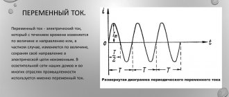
The vast majority of networks are powered by a three-phase system. Which is characterized by the fact that the voltage of each phase is shifted by 120º.
Rice. 1. Voltage form in a three-phase network
As you can see from Figure 1, diagram b) shows the operation of a balanced symmetrical system. Moreover, if you perform a geometric addition of the presented vectors, then at the zero point the result of the addition will be equal to zero. This means that in 110, 10 and 6 kV systems, which are characterized by grounding of the transformer neutrals, under normal operating conditions there will be no current in the neutral. It should also be noted that geometrically, phase changes can be divided into the following types:
For the first two options, the shift angle will be 120º.
Rice. 2. Direct, reverse and zero sequence
Look at Figure 2, here the zero sequence, unlike the other two, shows that the vectors have the same direction, but their displacement in space between themselves is 0º. A similar situation occurs with a single-phase short circuit, while the currents of the two remaining phases rush to the zero point. This situation can also be observed during phase-to-phase faults, when two of them, in addition to overlap, also reach the ground, and only one phase current will flow at zero.
If a three-phase short circuit occurs in the neutral of the windings, the current will not flow, despite the accident. Because zero sequence currents and voltages will still be absent. Despite the fact that phase voltages and currents in this situation can increase significantly in comparison with the nominal ones.
Operating principle of TZNP
Almost all relay protections, the action of which is adjusted against the appearance of zero-sequence currents, have a similar principle. Consider the following diagram demonstrating the effect of protection.
Schematic diagram of the simplest TZNP
Here is an option for switching on a current relay T, which is connected to the secondary windings of current transformers (CTs) assembled in a star. In this situation, the neutral wire from the star of the transformer windings filters out the zero sequence components if they occur. Provided that the system operates symmetrically, the windings of relay T will be de-energized. And provided that a ground fault occurs in one of the phases, the CT will react to this, causing current to flow through the neutral wire. This will be the very component of the zero sequence, due to which the relay winding T will be excited.
After which a time delay occurs, determined by the parameters of relay B. When the set period of time expires, the current protection sends a signal to the corresponding switching installation U, which disconnects the three-phase network. More complex circuit options may also include a power relay, which allows you to debug the operation of the protection in direction.
In the case of phase-to-phase damage, the symmetry will not be broken, but only the magnitude of the currents will change. And the CTs will continue to compensate for the currents flowing into the neutral wire. The advantage of this scheme is that at maximum operating currents, the protection will still not operate, since symmetry will be maintained.
But if there is a significant difference in the magnetic parameters of the measuring transformers, an imbalance will occur in the system, and an unbalance current will flow through the neutral conductor. This can cause false trips of current protection even in those networks where the rated power supply is observed.
Rules for selecting current transformers.
In order to reduce the imbalance that affects the correct operation of the current protection, CTs are selected in which secondary currents will not create overflows. Why should they meet the following requirements:
It is prohibited to connect any other load to their secondary circuits, leading to a distortion of the magnetization curve in at least one CT. Therefore, in practice, when operating currents arise from a symmetrical system, it is recommended to replace not one or two, but all three transformers at the same time.
Application area
Current protection, capable of responding to the appearance of a zero sequence, has found quite wide application in lines with a grounded neutral. Since short circuit currents in them reach the highest values. But with an isolated neutral, its installation is impractical, so TZNP are not used in them. Today, TZNP installations are widely used:
Use of 3Uo in protection
In networks with an isolated neutral, the joint use of zero-sequence voltages and currents makes it possible to determine the direction to the short circuit point. But there are now more effective methods for pinpointing the location of faults in these networks.
Such a scheme brings much greater benefit in networks with a solidly grounded neutral (power lines 110 kV and above).
Connecting a voltage of 3Uo (zero sequence) and a current of 3Io to the windings of the power direction relay allows you to determine whether a single-phase fault has occurred in the line or outside it. This ensures selectivity of the protection against single-phase ground faults.
What is zero sequence voltage? Schemes, application, physical meaning
The three-phase voltage system is symmetrical in normal operation. But as soon as a short circuit occurs, the symmetry is broken. For the convenience of recognizing types of short circuits and carrying out calculations, the method of symmetrical components is used. According to it, any three-phase system from the moment of short circuit can, for convenience of calculations, be represented as the sum of the voltages of three symmetrical systems:
All of them are imaginary quantities that do not exist in reality. But with the help of some tricks they can be made really tangible and put into practice.
Devices that extract voltage of the desired sequence from a three-phase voltage system are called filters. Let's consider one of these devices, used in practice to detect ground faults.
Selecting settings for TZNP
To ensure the stepwise principle of line output, the current protection that controls the appearance of a zero sequence in the circuits must correspond to the selectivity of operation. Here, selectivity refers to the sequential switching off of certain sections of the circuit, depending on their significance, in order to determine the location of the damage or highlight the damaged gap. To do this, select the appropriate time settings for protection. Consider an example of setting settings in this diagram.
Setting selection example
As you can see, in this case the TZNP is configured according to the same principle as the maximum current protection, but with a shorter time delay. In this example, each subsequent protection stage withstands a time delay for an interval Δt greater than the previous one. That is, the response time of the first current cutoff, in comparison with the second, will be calculated according to the formula: t1 = t2+ Δt. And the response time of the second in relation to the third will be t2 = t3+ Δt. Thus, each subsequent relay performs the function of backup protection.
If the windings of the converter devices are connected according to the star-delta system, as well as the star-star system, the TZNP of the primary and secondary circuits do not match. Due to the fact that a short circuit in high voltage lines will not necessarily cause the appearance of zero sequence components in the low windings and the circuit fed by them. Since the TZNP selectivity for each of them must be built independently, in practice their independent operation must be ensured.
This system of stepwise protection allows minimizing the further transfer of damage to other sections of the network and power equipment. It also helps to remove the personnel servicing these devices from danger. The main requirement for current protection is the prevention of false switching in relation to the corresponding trigger zone.
Practical implementation of TZNP
Today, current protection that responds to the occurrence of a zero sequence can be implemented by microprocessor units and through relays. In most cases, outdated relays are widely replaced with newer versions of current protection. But, in addition to TZNP, remote, differential protection and other devices are configured for operation. Whose work is based on both symmetrical components and other network parameters.
In addition, in its classic design, TZNP does not have the ability to determine the location of damage. That is, it does not matter to her where the break occurred. Therefore, directional protection is used to determine the direction in which current flows towards ground. Such a system is built not only on currents, but also on voltage arising from the zero sequence. These values are supplied from voltage transformers connected in an open delta system.
Directional protection operating diagram
When there is a short circuit in the current protection redundancy zone, voltage is supplied to one of the windings of the power relay, and a zero-sequence current used for current protection is supplied to the second winding. Provided that the power vector is directed into the line, the power relay unblocks the operation of the current protection. Otherwise, when the power direction indicates that the fault has occurred in another section, the power relay will continue to block the current protection from tripping.
Today, the practical implementation of such protection is carried out using REL650 microprocessor units or EPZ-1636 relays. Each of which already includes current cut-off, distance protection, and a starting relay to restore power.
Zero sequence current is:
The sum of the instantaneous values of the currents of the three phases of a three-phase system The zero-sequence system differs significantly from the direct and reverse ones in that there is no phase shift. The zero current system essentially represents three single-phase currents, for which the three wires of the three-phase circuit represent the forward wire, and the return wire is the ground or the fourth (zero), through which the current returns.
Negative sequence components (current, voltage) arise when any asymmetry appears in the network (phase loss, inclusion of an asymmetric load, single-phase or two-phase short circuit). Zero sequence components appear when one or two phases are broken, single-phase or two-phase short circuit to ground. (for phase-to-phase faults without ground, the components are equal to zero) Negative sequence current, as is known from [22], appears during any asymmetrical short circuit, and briefly during a three-phase short circuit. The zero sequence current is used to increase the sensitivity of starting the RF transmitter during a short circuit to ground, and the starting relay of the phase current of the spacecraft is used for symmetrical short circuits
Zero sequence components appear when one or two phases are broken, single-phase or two-phase short circuit to ground. (for phase-to-phase faults without earth, the components are zero) Zero sequence currents are essentially a single-phase current, branched between three phases and returning through the earth and circuits parallel to it. Because of this, the circulation path of zero-sequence currents
sharply different from the path along which direct or negative sequence currents pass. For the practical implementation of the method of symmetrical components, it is necessary to construct three equivalent circuits: direct, negative and zero sequence. The configuration of these circuits and the parameters of their elements are generally not the same.
The positive sequence diagram is the same as for calculating the three-phase fault current. From this circuit the resulting EMF and the resulting positive sequence resistance are found:
And . The beginning of this circuit is the point of zero potential of the power sources, the end is the location of the short circuit to which positive sequence voltage is applied. Negative sequence components occur when any asymmetry appears in the network: single-phase or two-phase short circuit, phase loss, load unbalance.
Zero-sequence components occur during ground faults (single- and two-phase) or when one or two phases are broken. In the case of a phase-to-phase fault, the zero sequence components (currents and voltages) are equal to zero.
This method is used by many relay protection and automation devices. In particular, the operating principle of a zero-sequence current transformer is based on the addition of current values in all three phases of the protected area. In normal (symmetrical) mode, the sum of the phase current values is zero. In the event of a single-phase fault, zero-sequence currents will appear in the network and the sum of the current values in the three phases will be different from zero, which will be recorded by a measuring device (for example, an ammeter) connected to the secondary winding of the zero-sequence current transformer.
The three-phase voltage system is symmetrical in normal operation. But as soon as a short circuit occurs, the symmetry is broken. For the convenience of recognizing types of short circuits and carrying out calculations, the method of symmetrical components is used. According to it, any three-phase system from the moment of short circuit can, for convenience of calculations, be represented as the sum of the voltages of three symmetrical systems:
All of them are imaginary quantities that do not exist in reality. But with the help of some tricks they can be made really tangible and put into practice.
Devices that extract voltage of the desired sequence from a three-phase voltage system are called filters. Let's consider one of these devices, used in practice to detect ground faults.