Today, interest in LEDs has increased significantly, because they are the future in lighting. The question arises of how an LED is connected to a 220 V network, which we will answer in detail in this article. We will also consider the supply voltage, pinout, pinout, connection diagrams and various calculations.
An LED is a semiconductor device where electric current turns into light. A diode allows current to flow in only one direction. LEDs are connected to 220V thanks to a driver that meets all the characteristics.
The connection according to the scheme can be parallel or serial. The LED is characterized by a durable housing, long and reliable operation.
How does an LED work?
A conventional indicator LED is made in an epoxy housing with a diameter of 5 mm and two contact leads for connection to electric current circuits: an anode and a cathode. Visually they differ in length. The new device without cut contacts has a shorter cathode.
- A simple rule helps to remember this position: both words begin with the letter “K”:
- cathode;
- Briefly speaking.
When the legs of the LED are cut off, the anode can be determined by applying a voltage of 1.5 volts to the contacts from a simple AA battery: light appears when the polarities match.
How does an LED work? The light-emitting active semiconductor single crystal has the shape of a rectangular parallelepiped. It is placed near a parabolic-shaped reflector made of aluminum alloy and mounted on a substrate with non-conducting properties.
At the end of the light transparent body made of polymer materials there is a lens that focuses the light rays. Together with the reflector, it forms an optical system that shapes the angle of radiation flux. It is characterized by the directional pattern of the LED.
It characterizes the deviation of light from the geometric axis of the overall structure to the sides, which leads to increased scattering. This phenomenon occurs due to the appearance of minor technology violations during production, as well as the aging of optical materials during operation and some other factors.
At the bottom of the case there can be an aluminum or brass belt that serves as a radiator to remove the heat generated by the passage of electric current.
This design principle is widely accepted. On its basis, other semiconductor light sources are created, using other forms of structural elements.
Glow in a semiconductor crystal occurs when electrons and holes recombine in the region of the pn junction. The pn junction region is formed by the contact of two semiconductors with different types of conductivity. To do this, the near-contact layers of the semiconductor crystal are doped with different impurities: acceptor impurities on one side, donor impurities on the other.
LEDs based on gallium phosphide and arsenide, emitting in the yellow-green, yellow and red regions of the spectrum, were developed back in the 60s and 70s of the last century. They were used in light indicators, displays, dashboards of cars and airplanes, advertising screens, and various information visualization systems.
In terms of light output, LEDs have surpassed conventional incandescent lamps. They also surpassed them in durability, reliability, and safety. For a long time there were no blue, blue-green and white LEDs.
The color of the LED depends on the band gap in which electrons and holes recombine, that is, on the semiconductor material and dopant impurities. The “blue” the LED, the higher the energy of the quanta, which means the larger the bandgap should be.
Blue LEDs have been produced using semiconductors with a large band gap—silicon carbide, compounds of group II and IV elements, or nitrides of group III elements. However, SiC-based LEDs turned out to have too low efficiency and low quantum yield (that is, the number of emitted quanta per recombined pair).
LEDs based on solid solutions of zinc selenide ZnSe had a higher quantum yield, but they overheated due to high resistance and were short-lived. The first blue LED was produced using gallium nitride films on a sapphire substrate.
Quantum yield is the number of light quanta emitted per recombined electron-hole pair. A distinction is made between internal and external quantum efficiency. Internal - in the pn junction itself, external - for the device as a whole (after all, light can be lost “along the way” - absorbed, scattered).
The internal quantum efficiency for good crystals with good heat dissipation reaches almost 100%, the record external quantum efficiency for red LEDs is 55%, and for blue LEDs - 35%. External quantum efficiency is one of the main characteristics of LED efficiency.
White light from LEDs can be obtained in several ways. The first is to mix colors using RGB technology. Red, blue and green LEDs are densely placed on one matrix, the radiation of which is mixed using an optical system, for example, a lens. The result is white light.
The second method is that three phosphors are applied to the surface of an LED emitting in the ultraviolet range (there are some), emitting blue, green and red light, respectively. Based on the principle of a fluorescent lamp.
The third method is when a yellow-green or green-red phosphor is applied to a blue LED. In this case, two or three radiations are mixed, forming white or close to white light.
LED supply voltage
Despite the fact that the No. 1 electrical parameter for an LED is the rated current, it is often necessary to know the voltage at its terminals for calculations. The term “LED voltage” refers to the potential difference across the pn junction in the open state.
It is a reference parameter and, together with other characteristics, is indicated in the passport for the semiconductor device. 3, 9 or 12 volts... Often you come across specimens about which nothing is known. So how do you find out the voltage drop across an LED?
- Theoretical method
An excellent clue in this case is the color of the glow, the external shape and dimensions of the semiconductor device. If the LED housing is made of a transparent compound, then its color remains a mystery, which a multimeter will help you solve.
To do this, turn the switch of the digital tester to the “check for break” position and touch the LED terminals one by one with the probes. A healthy element in forward bias will exhibit a slight glow from the crystal. Thus, we can draw a conclusion not only about the color of the glow, but also about the performance of the semiconductor device.
Light-emitting diodes of different colors are made from different semiconductor materials. It is the chemical composition of the semiconductor that largely determines the supply voltage of the LEDs, or more precisely, the voltage drop across the pn junction.
Due to the fact that dozens of chemical compounds are used in the production of crystals, there is no exact voltage for all LEDs of the same color. However, there is a certain range of values, which are often sufficient to carry out preliminary calculations of the elements of an electronic circuit.
On the one hand, the size and appearance of the housing do not affect the forward voltage of the LED. But in other way. through the lens you can see the number of emitting crystals that can be connected in series. The phosphor layer in SMD LEDs can hide an entire chain of crystals.
A striking example is the miniature multi-chip LEDs from Cree, whose voltage drop is often well above 3 volts. In recent years, white SMD LEDs have appeared, the housing of which contains 3 crystals connected in series. They can often be found in Chinese 220 volt LED lamps.
Naturally, it will not be possible to verify the serviceability of the LED crystals in such a lamp using a multimeter. The standard tester battery produces 9 V, and the minimum response voltage of a three-crystal white light-emitting diode is 9.6 V. There is also a two-crystal modification with a response threshold of 6 volts.
- Practical method
The most accurate data on the forward voltage drop across an LED can be obtained through practical measurements. To do this, you will need an adjustable DC power supply (PSU) with a voltage from 0 to 12 volts, a voltmeter or multimeter and a 510 Ohm resistor (more is possible). The laboratory circuit for testing is shown in the figure.
Everything is simple here: a resistor limits the current, and a voltmeter monitors the forward voltage of the LED. Smoothly increasing the voltage from the power source, observe the increase in readings on the voltmeter. When the triggering threshold is reached, the LED will begin to emit light.
At some point, the brightness will reach the nominal value, and the voltmeter readings will stop increasing sharply. This means that the pn junction is open, and a further increase in voltage from the output of the power supply will be applied only to the resistor. The current reading on the screen will be the nominal forward voltage of the LED.
If you continue to increase the power supply to the circuit, then only the current through the semiconductor will increase, and the potential difference across it will change by no more than 0.1-0.2 volts. Excessive current will lead to overheating of the crystal and electrical breakdown of the pn junction.
If the operating voltage on the LED is set to about 1.9 volts, but there is no glow, then the infrared diode may be tested. To verify this, you need to direct the radiation flow to the turned on phone camera. A white spot should appear on the screen.
In the absence of an regulated power supply, you can power the LED “crown” at 9 V. You can also use a 3 or 9 volt network adapter in the measurements, which produces a rectified stabilized voltage, and recalculate the value of the resistor.
A little theory
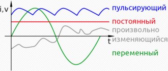
An LED requires a constant voltage or current to operate properly. They should be:
- Constant in direction. That is, the current in the LED circuit when voltage is applied must flow from the “+” of the voltage source to its “–”.
- Stable, i.e. constant in value, during the operating time of the diode.
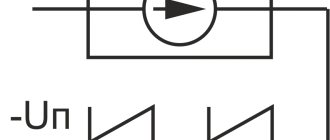
- Not pulsating - after rectification and stabilization, the values of constant voltage or current should not change periodically.
Diagram of the voltage waveform at the output of a full-wave rectifier when filtered by an electrolytic capacitor (in the diagram there are black and white rectangles marked “+”). The dotted line is the voltage at the rectifier output. The capacitor is charged to a half-wave amplitude and gradually discharged across the load resistance. “Steps” are pulsations. The ratio of the step and half-wave amplitudes as a percentage is the ripple factor.
For LEDs, the available voltage sources were initially used - 5, 9, 12 V. And the operating voltage of the pn junction is from 1.9-2.4 to 3.7-4.4 V. Therefore, turning on the diode directly is almost always its physical combustion from overheating with high current. The current must be limited by a current-limiting resistor, wasting energy on heating it.
LEDs can be switched on in series, several at a time. Then, by assembling a chain of them, the sum of their direct voltages can be used to almost reach the voltage of the power source. And “pay off” the remaining difference by dissipating it in the form of heat on a resistor.
When there are dozens of diodes, they are connected in series circuits that are connected in parallel.
LED pinout
There are only 3 ways to resolve the issue:
- Structurally
According to standards accepted throughout the world, on a regular LED (not SMD type), the long leg is always the “+” or the anode. For an LED to work, a positive half-wave must be supplied to it. And the short one is the cathode.
- Using a multimeter
To check, you need to set the device switch to the “Test” mode and install the red multimeter probe on the anode, and the black probe on the cathode. As a result, the LED should light up. If this does not happen, you need to change the polarity (black to the anode, and red to the cathode).
- Visually
If you look closely at the LED, you can see 2 tips near the crystal. The larger one is the cathode, the smaller one is the anode.
Features of LED lamps
Modern LED lamps are more complex than their incandescent filament predecessors. To operate LEDs, a number of electronic components are required, which are located on a printed circuit board.
All structural elements are compactly hidden inside the case. The light sources themselves take up a minimal amount of space in the lamp.
The weak point of inexpensive LED lamps is the capacitors, the low quality of which leads to pulsating light. In addition, they can burn out before the LEDs themselves.
The design of a standard LED lamp includes the following components:
- Light diffuser made of plastic. Promotes uniform distribution of light flux in all directions around the lamp.
- Printed circuit board with capacitors, voltage converters and other electronic components.
- LEDs. Their number and operating voltage are in strict accordance with the built-in electronic circuit.
- Aluminum radiator designed to remove heat from high-power lamps.
- Ventilation slots provide passive cooling of the board and LEDs.
- The socket with which the lamp is attached to the lamp.
Thus, an LED lamp is a device with a complex internal structure. It is demanding on external temperature and power supply parameters.
LED pinout
By pinout we usually understand the appearance (body design) of the LED. Each manufacturer produces LEDs in its own housing, depending on the structure and purpose. There is no single standard, as in LED lamps; let me remind you that the most common lamp bases are: e27, e14.
There is no single standard for LED pinout. Each manufacturer does as they see fit. As a result, on store shelves we get a lot of LEDs that differ in shape, appearance, and design.
From the whole set, it is still possible to single out a couple of small groups. For example, the most common simple LEDs are made in a transparent or colored housing made of durable plastic or glass, and have the shape of a cylinder, the edge of which is most often rounded.
More expensive LEDs consist of several parts: a base and a lens. There are conductive tracks on the base, and the lens is made of high-quality material, which serves as a light diffuser.
The base is made in the form of a circle or square. Polarity on a square is indicated by a beveled corner. For example, CREE LEDs look like this:
A non-standard pinout may occur when repairing electronic units and cause certain difficulties in determining polarity. The pinout of the LED determines its polarity, knowledge of which is required for repair or correct installation of the LED in the circuit.
It is not always possible to determine the polarity in the usual ways, due to the non-standard pinout of the LED: the special structure of the housing, the thickening of one of the LEDs and other reasons. Therefore, in such cases, whatever one may say, you will have to resort to electrical measurement.
Designation of LEDs on the diagram
The LED in the diagram is indicated as a regular diode with two arrows pointing to the side, indicating the emission of light. The diode itself can be depicted either in a circle or without it.
On the side of the nose of the triangle there is a cathode, and on the side of the back of the triangle there is an anode. Sometimes on the diagram you can see the designations of the anode and cathode in the form of the letters A and K or + and -, which respectively mean anode and cathode or plus and minus.
The semiconductor element is signed on domestic circuits with the letters HL (HL1, HL2, etc.) - this is according to GOST. In foreign standards, the LED designation on the diagram is similar to the Russian one. It is signed with a different word - LED (LED1, LED2, LED3, etc.), which translated from English stands for light - emitting diode - light-emitting diode.
Do not confuse the designation of an LED on the diagram with a photodiode. At first glance it may seem that they are the same, however, upon closer examination, a significant difference is visible: the arrows of the photoresistor are directed towards the diode (a triangle with a stick at the sharp end).
The second difference is the letter designation of the photoresistor - VD or VB, which means photocell.
In conclusion, I would like to say that labeling is very important. Knowing its decoding allows you to determine the main parameters of the LED without opening the datasheet. It is unrealistic to remember the markings of all manufacturers, and there is no need; it is enough to know the decoding of the main brands.
Leading manufacturers of LED lamps
World-famous manufacturers of LED products value their image, and therefore strive to produce lamps with parameters that fully correspond to the declared ones.
The best manufacturers of premium LED lamps are:
- Philips;
- Osram;
- Eurolamp;
- Gauss.
The prices for the products of the listed companies are the highest, but the quality of the lamps is excellent.
The difference in the cost of lamps of the same power from the best brands and cheap manufacturers is only 30-70%, so it is recommended to buy more reliable models
The middle price segment in the production of LED lamps is occupied by the following companies:
- Feron;
- Camelion;
- Jazzway;
- Estares;
- Era;
- Navigator;
- Ecola;
- Optogan.
These companies strive to use inexpensive components in production without severely compromising quality. Often their lamps break in the first days of operation, but are replaced under warranty without any problems.
It is not recommended to buy LED products from little-known Chinese and domestic brands, because their warranty period rarely exceeds 4-6 months. In addition, they do not care about the brand image, which means they can freely use second-class components in production.
Serial connection of LEDs
When connected in series through a current-limiting resistor, several LEDs are assembled into one chain, and the cathode of the previous one is soldered to the anode of the next one:
In the circuit, one current (20mA) will flow through all LEDs, and the voltage level will consist of the sum of the voltage drop across each. This means that using this connection diagram, you cannot include any number of LEDs in the circuit, because it is limited by voltage drop.
Voltage drop is the level of voltage that a light-emitting diode converts into light energy (glow).
For example, in the circuit the voltage drop across one LED will be 3 Volts. There are a total of 3 LEDs in the circuit. Power supply 12V. We consider 3 Volts * 3 led = 9 V - voltage drop.
After simple calculations, we see that we cannot include more than 4 LEDs (3 * 4 = 12V) in a series connection circuit, powering them from a regular car battery (or other source with a voltage of 12V).
If we want to connect more LEd in series, we will need a power supply with a higher rating.
This scheme was quite often found in Christmas tree garlands, however, due to one significant drawback, modern LED garlands use a mixed connection. We'll look at what the drawback is below.
- Disadvantages of serial connection:
- If at least one element fails, the entire circuit becomes inoperative.
- To power a large number of LEDs you need a high voltage source.
Features of LED strip operation from a 220V network
Absolutely all products that are manufactured in factories are designed to be connected to a DC network, which has a voltage of 12V. To do this you need to use a special power supply. In addition, today there is a scheme that makes it possible to install it, but at the same time, in such a situation, something needs to be further refined.
If the LEDs that are on the strip are designed for a lower voltage, then in this situation you need to do the following:
- If the tape has an operating voltage of 12V and a length of 5 meters, then it needs to be cut into 20 parts;
- The 220V network must be rectified by using a special diode bridge;
- Then connect the pieces of LED strip together so that the output with a positive value is connected to the negative output on the next segment;
- If you notice even a slight flicker in the future, it can be eliminated by using a special capacitor.
How to properly connect an LED strip: diagram
It is very important to check the amount of current flowing through the tracks. If it is higher than normal, then an additional resistor or a few more pieces should be included in the chain of segments
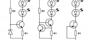
Parallel connection of LEDs
In this situation, everything happens the other way around. Each LED has the same voltage level, and the current is the sum of the currents passing through them.
Following from the above, we conclude that if we have a 12V source and 10 LEDs, the power supply must withstand a load of 0.2A (10 * 0.002). Based on the above calculations, for a parallel connection you will need a current-limiting resistor with a nominal value of 2.4 Ohms (12 * 0.2).
This is a deep misconception!!! Why? You will find the answer below.
The characteristics of each LED, even of the same series and batch, are always different. In other words: in order for one to light up, it is necessary to pass through it a current with a nominal value of 20 mA, and for the other this nominal value may already be 25 mA.
Thus, if only one resistance is installed in the circuit, the nominal value of which was calculated earlier, different currents will flow through the LEDs, which will cause overheating and failure of LEDs designed for a nominal value of 18 mA, and more powerful ones will shine at only 70% of the nominal value .
Based on the above, it is worth understanding that when connecting in parallel, it is necessary to install a separate resistance for each.
- Disadvantages of parallel connection:
- A large number of elements.
- When one diode fails, the load on the others increases.
Mixed connection
This connection method is the most optimal. All LED strips are assembled using this principle. It involves a combination of parallel and serial connections. You can see how it is done in the photo:
The circuit involves connecting in parallel not individual LEDs, but serial chains of them. As a result of this, even if one or more chains fail, the LED garland or strip will still shine equally.
We looked at the main ways to connect simple LEDs. Now let's look at the methods for connecting high-power LEDs, and what problems you may encounter if connected incorrectly.
How to connect an LED to a 220 volt network
An LED is a type of semiconductor diode with a supply voltage and current much lower than in a household electrical network. If connected directly to a 220 volt network, it will instantly fail.
Therefore, the light-emitting diode must be connected only through a current-limiting element. The cheapest and easiest to assemble are circuits with a step-down element in the form of a resistor or capacitor.
The first thing you need to know when connecting to a 220V network is that for a nominal glow, a current of 20 mA must pass through the LED, and the voltage drop across it should not exceed 2.2-3V. Based on this, it is necessary to calculate the value of the current-limiting resistor using the following formula:
- Where:
- 0.75 – LED reliability factor;
- U power is the voltage of the power source;
- U pad is the voltage that drops across the light-emitting diode and creates a luminous flux;
- I – rated current passing through it;
- R – resistance rating for regulating the passing current.
After appropriate calculations, the resistance value should correspond to 30 kOhm.
However, do not forget that a large amount of heat will be generated at the resistance due to the voltage drop. For this reason, it is additionally necessary to calculate the power of this resistor using the formula:
For our case, U will be the difference between the supply voltage and the drop voltage across the LED. After appropriate calculations, to connect one LED, the resistance power should be 2W.
An important point that you need to pay attention to when connecting an LED to an AC network is the reverse voltage limitation. This task can easily be accomplished by any silicon diode designed for a current no less than that flowing in the circuit. The diode is connected in series after the resistor or with reverse polarity in parallel with the LED.
There is an opinion that it is possible to do without limiting the reverse voltage, since electrical breakdown does not cause damage to the light-emitting diode. However, reverse current can cause the pn junction to overheat, resulting in thermal breakdown and destruction of the LED crystal.
Instead of a silicon diode, you can use a second light-emitting diode with a similar forward current, which is connected in reverse polarity in parallel with the first LED. The downside to current-limiting resistor circuits is that they require a lot of power dissipation.
This problem becomes especially relevant when connecting a load with a large current consumption. This problem is solved by replacing the resistor with a non-polar capacitor, which in such circuits is called ballast or quenching.
A non-polar capacitor connected to an AC network behaves like a resistance, but does not dissipate the power consumed in the form of heat.
In these circuits, when the power is turned off, the capacitor remains undischarged, which creates a risk of electric shock. This problem is easily solved by connecting a 0.5-watt shunt resistor with a resistance of at least 240 kOhm to the capacitor.
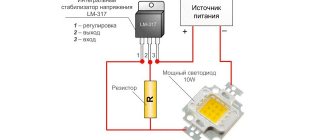
Calculation of a resistor for an LED
In all of the above circuits with a current-limiting resistor, the resistance is calculated according to Ohm's law:
R = U/I
- Where:
- U is the supply voltage;
- I – LED operating current.
The power dissipated by the resistor is P = U * I.
If you plan to use the circuit in a low-convection package, it is recommended to increase the maximum power dissipation value of the resistor by 30%.
Calculation of a quenching capacitor for an LED
Calculation of the capacity of the quenching capacitor (in μF) is carried out using the following formula:
C = 3200*I/U
- Where:
- I is the load current;
- U – supply voltage.
This formula is simplified, but its accuracy is sufficient for connecting 1-5 low-current LEDs in series.
To protect the circuit from voltage surges and impulse noise, a quenching capacitor must be selected with an operating voltage of at least 400 V.
It is better to use a ceramic capacitor of the K73–17 type with an operating voltage of more than 400 V or its imported equivalent. Electrolytic (polar) capacitors must not be used.
Safety precautions
Safety precautions when working in existing installations are regulated by the Labor Safety Rules for the operation of electrical installations. They do not apply to the home workshop, but their basic principles must be taken into account when connecting an LED to a 220 V network. The main safety rule when working with any electrical installation is that all work must be performed when the voltage is removed, excluding erroneous or involuntary, unauthorized activation. After turning off the switch, the absence of voltage must be checked with a tester. Everything else is the use of dielectric gloves, mats, temporary grounding, etc. This is difficult to do at home, but we must remember that there are never enough safety measures.
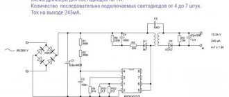
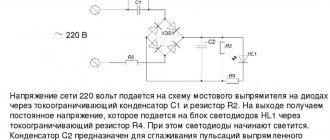
220 volt ice driver circuit
The 220 volt ice driver circuit is nothing more than a switching power supply.
As a homemade LED driver from a 220V network, we will consider the simplest switching power supply without galvanic isolation. The main advantage of such schemes is simplicity and reliability.
But be careful when assembling, since this circuit has no current limit. The LEDs will draw their required one and a half amperes, but if you touch the bare wires with your hand, the current will reach ten amperes, and such a shock is very noticeable.
- The simplest driver circuit for 220V LEDs consists of three main stages:
- capacitive voltage divider;
- diode bridge;
- voltage stabilization cascade.
The first stage is capacitance on capacitor C1 with a resistor. The resistor is necessary for self-discharge of the capacitor and does not affect the operation of the circuit itself. Its rating is not particularly critical and can be from 100 kOhm to 1 Mohm with a power of 0.5-1 W. The capacitor is necessarily non-electrolytic at 400-500V (effective peak voltage of the network).
When a half-wave of voltage passes through a capacitor, it passes current until the plates are charged. The smaller its capacity, the faster the full charge occurs. With a capacity of 0.3-0.4 μF, the charging time is 1/10 of the half-wave period of the mains voltage.
In simple terms, only a tenth of the incoming voltage will pass through the capacitor.
The second stage is a diode bridge. It converts alternating voltage to direct voltage. After cutting off most of the half-wave voltage with a capacitor, we get about 20-24V DC at the output of the diode bridge.
The third stage is a smoothing stabilizing filter. A capacitor with a diode bridge acts as a voltage divider. When the voltage in the network changes, the amplitude at the output of the diode bridge will also change.
To smooth out the voltage ripple, we connect an electrolytic capacitor in parallel to the circuit. Its capacity depends on the power of our load. In the driver circuit, the supply voltage for the LEDs should not exceed 12V. The common element L7812 can be used as a stabilizer.
The assembled circuit of a 220-volt LED lamp begins to work immediately, but before connecting it to the network, carefully insulate all exposed wires and soldering points of circuit elements.
Driver option without current stabilizer
There are a huge number of driver circuits on the network for LEDs from a 220V network that do not have current stabilizers.
The problem with any transformerless driver is the ripple of the output voltage, and therefore the brightness of the LEDs. A capacitor installed after the diode bridge partially copes with this problem, but does not completely solve it.
There will be ripple on the diodes with an amplitude of 2-3V. When we install a 12V stabilizer in the circuit, even taking into account ripple, the amplitude of the incoming voltage will be higher than the cutoff range.
Voltage diagram in a circuit without a stabilizer
Diagram in a circuit with a stabilizer
Therefore, a driver for diode lamps, even one assembled with one’s own hands, will not be inferior in pulsation level to similar units of expensive factory-made lamps.
As you can see, assembling the driver with your own hands is not particularly difficult. By changing the parameters of the circuit elements, we can vary the output signal values within wide limits.
If you want to build a 220-volt LED floodlight circuit based on such a circuit, it is better to convert the output stage to 24V with an appropriate stabilizer, since the output current of the L7812 is 1.2A, this limits the load power to 10W.
For more powerful lighting sources, it is necessary to either increase the number of output stages, or use a more powerful stabilizer with an output current of up to 5A and install it on a radiator.
You need to know this
The main thing is to remember safety precautions. The presented circuits are powered by 220 V AC, and therefore require special attention during assembly. Connecting the LED to the network must be carried out in strict accordance with the circuit diagram.
Deviation from the diagram or negligence can lead to a short circuit or failure of individual parts. When you turn it on for the first time, it is recommended to let the assembly work for a while to make sure it is stable and does not overheat the elements.
To increase the reliability of the device, it is recommended to use previously tested parts with a margin of maximum permissible voltage and power values. You should carefully assemble transformerless power supplies and remember that they do not have galvanic isolation from the network.
The finished circuit must be reliably isolated from adjacent metal parts and protected from accidental contact. It can only be dismantled with the power supply switched off.
Author: Sergey Vladimirovich, electrical engineer. More about the author.
Tips for choosing LED lamps
When purchasing LED devices, it is important to pay attention to both their technical characteristics and a number of other nuances.
The best way to choose an LED lamp that is comfortable for the eyes is to turn on several models in the store at the same time and compare their luminosity
The tips presented will help you purchase a high-quality lamp that will last a long time and be comfortable for the eyes.
- The packaging of LED lamps must contain an inscription stating that there is no pulsation.
- The luminous flux must be greater than that of the incandescent lamp being replaced.
- It is recommended to compare the glow of lamps of the same power in the store.
- If you have a switch with an indicator, it is advisable to first make sure that LED lamps work correctly with it.
- Ceiling lamps with a small beam angle can cause glare.
- It is recommended to buy lamps from large stores that provide a minimum of 2 years of warranty.
It is advisable to purchase lamps only from well-known manufacturers, because products from cheap, little-known brands often do not correspond to the characteristics stated on the packaging.