Current and voltage measurement
DC measurements
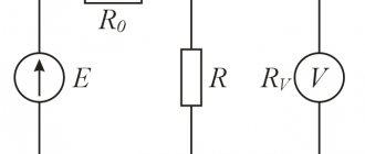
Direct current and voltage measurements are made using instruments of magnetoelectric, electromagnetic, electrodynamic systems; voltage is also measured by electrostatic and electronic voltmeters. In addition, DC compensators are used for more accurate measurements.
Magnetoelectric measuring mechanisms are directly micro- and milliammeters or millivoltmeters, and in combination with shunts and additional resistances - ammeters and voltmeters, respectively.
To measure and detect small currents (10-11 - 10-5 A) and voltages (less than 10-4 V), galvanometers are used - highly sensitive measuring mechanisms, usually of a magnetoelectric system. Unlike instruments whose scales are graduated in measured quantities, galvanometers have an unnamed scale, the division value of which is indicated in the passport data of the device or is determined experimentally.
Measuring direct currents and voltages can be done using ammeters and voltmeters of electromagnetic and electrodynamic systems. They are mainly used for measurements in alternating current circuits.
Electrostatic measuring mechanisms are electrostatic voltmeters because they can directly measure voltage. The range of voltages they measure ranges from tens of volts to hundreds of kilovolts. To measure voltages up to 3 kV, measuring mechanisms with varying activity of the electrode surface are used. Voltmeters are manufactured as single-limit and multi-limit, portable (up to 30 kV) and stationary (for measuring high voltages, over 30 kV).
The accuracy class of modern electrostatic voltmeters reaches 0.1 and even 0.05 (S-71), however, devices of classes 1.5 are most often manufactured; 2 and 2.5. To reduce the influence of external electrostatic fields, electrostatic shielding is used. The measurement limits are expanded using resistor voltage dividers.
The main advantages of electrostatic voltmeters are: very low inherent power consumption (high input resistance, 1010 Ohms), the ability to measure direct and alternating voltages, and the ability to directly measure high voltages. Disadvantages include low sensitivity and uneven scale.
Measurement of direct voltages from fractions of a volt to several kilovolts can be carried out using electronic voltmeters, which contain a measuring mechanism and a DC tube or transistor amplifier. There are several types of electronic DC voltmeters, but they are all characterized by the block diagram shown in Figure 6.1. 6.1.
Rice.
6.1. Block diagram of an electronic constant voltage voltmeter: a) with dial reading; b) with digital readout
The input device (voltage divider), to which voltage UX is applied, allows you to change the measurement limits and provides a high input impedance of the device.
A magnetoelectric microammeter with a measurement range of 50–500 μA is usually used as a measuring mechanism.
DC amplifiers are designed to increase the sensitivity of the device, increasing the power of the measured signal to a level that ensures the required deviation of the measuring mechanism pointer. The amplifiers have high input and low output impedance. This ensures matching of the input resistance of the voltmeter (10 - 20 MOhm) with the low internal resistance of the microammeter. Most often, amplifiers are made in the form of bridge circuits with feedback.
Electronic voltmeters with pointer reading have the following features: high input resistance and, therefore, low power consumption from the measurement object; high sensitivity with a large measuring range; ability to withstand overloads; relatively low measurement speed (due to the inertia of the magnetoelectric measuring mechanism); need for power (from mains or battery); large errors (the main reduced error is 2 - 3%).
Nowadays, of course, digital voltmeters have become more widespread - devices with a digital reading device and an analog-to-digital converter in which voltage (or other physical quantities; frequency, phase shift, etc.) are automatically converted into a digital code. Such devices have a number of advantages over pointer devices: they have a wide range of measured voltages (from 1 mV to 1000 V), speed, and allow measurements with small errors (0.01 - 0.005), since the operating principle of most devices is based on the comparison method, and Digital reading eliminates reading errors. Digital voltmeters also allow you to enter measurement data directly into computers, which allows you to further process the received data more quickly.
Disadvantages include the complexity of the device, less reliability and high cost.
There are various principles for constructing digital DC voltmeters:
- According to the type of elements used in the circuits, they are divided into:
- electromechanical;
- combined.
electronic;
- spatial coding;
intermediate conversion (to time interval, frequency, phase, etc.);
A generalized block diagram of an electronic digital voltmeter is presented in Figure 6.2. 6.2.
Rice.
6.2. Generalized structure diagram of an electronic digital voltmeter
The input device is a high-resistance resistance (about 10 MOhm) or a cathode (emitter) follower with a calibrated divider.
A comparison device (null organ) is used to compare the measured and reference voltages.
Control devices consist of a pulse generator that sets measurement cycles and controls the operation of logic circuits.
The voltage-to-code converter creates a reference voltage UOBR, which is supplied to the comparing device.
An electronic key is a device that turns on or switches the output voltage under the influence of one or more input voltages, called control voltages.
Electronic meters read the measured voltage in a digital code (usually in a binary system).
How to avoid getting injured when taking measurements?
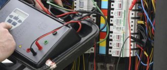
To be on the safe side, if in doubt, it is better to read the instructions for the electrical appliance and check that the connection is correct. When taking measurements, it is important to remember about protective measures when working with electric current. Injury can occur even when working with low-current devices. Especially in conditions with high humidity. It is necessary to work in rubberized overalls.
To study ST, scientists came up with measuring electrical devices. Due to the low internal resistance, these meters do not affect the parameters of the electric current in the measured current circuit. The devices are actively used at industrial sites and at home.
Source
Three resistances in one shunt resistor
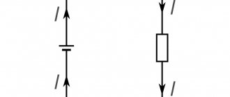
Despite their appearance, modern shunt resistors are not as simple as they seem. Specifically, the resistance of a shunt resistor is actually made up of three parts (Figure 2). First, there is the resistance of the shunt resistor itself. Then, there are the resistances of the terminals of this resistor and the traces on the circuit board connected to the shunt resistor. Typically the lead and trace resistances are negligible, but the shunt resistors themselves usually have very low resistance values. When measuring large currents, even small lead resistances introduce an error into the measurement results, since they are not taken into account by the manufacturer in the shunt resistor specifications.
Rice. 2. A two-terminal current shunt resistor actually consists of three resistances connected in series: the resistance of the shunt resistor itself (Rshunt), the resistance of the two leads of the resistor (Rlead), and the resistance of the lead paths on the board connected to the resistor (not shown). Lead resistance may cause measurement error for large currents.
One way to avoid measurement errors introduced by external lead resistances is to create a Kelvin connection by making separate current sense paths to a two-terminal shunt resistor (Figure 3).
Rice. 3. Kelvin connection with two-terminal current sensing resistor reduces the measurement error caused by the resistance of the resistor leads and PCB traces. An example image of two-terminal current shunt resistors is shown on the right.
In this configuration, the current flowing through the current shunt resistor is routed through wide lead traces on the PCB. Much narrower traces, which are not in the main current path, but located directly next to the resistive element of the shunt resistor, remove the voltage dropped across it and transfer it to the AFE input. The separation of current-carrying and current-sensing contacts characterizes the Kelvin connection.
The resulting schematic representation of a Kelvin connection using a two-terminal shunt resistor is shown in Fig. 4.
Rice. 4. Using a Kelvin connection with a two-terminal shunt resistor removes the voltage measurement lines from the main current circuit, resulting in a more accurate voltage measurement across the shunt resistor
A very small current flows through the two current sense resistors (Rsense) shown in Fig. 4 because they are connected to the high-impedance inputs of the amplifier or ADC, which makes their resistance much less critical than the resistance values of the terminals through which the high current of the shunt resistor flows. Therefore, the voltage drop across Rsense resistors is quite small and is not a significant source of error when measuring current.
Which is better, two pins or four?
As can be seen from the circuit board wiring diagram in Fig. 3, it is impossible to completely eliminate lead resistance in a two-terminal shunt resistor even when using a Kelvin connection. Some tolerance must be specified for the PCB placement to account for positioning error when the shunt resistor is positioned to be soldered onto the PCB.
In addition, the TCR of the PCB copper traces (3900 ppm/?C) is much higher than the TCR of the shunt resistor element (often less than 50 ppm/?C). These parametric differences cause the resistance change in the PCB traces to be much greater than in the current sensing resistor, resulting in a higher temperature dependence of the current sensing circuit.
When using a two-terminal shunt resistor with a Kelvin connection, often the level of accuracy for current sensitivity may not be sufficient in many very high current applications. For such cases, manufacturers offer four-terminal shunt resistors, in which the Kelvin connection is implemented inside the resistor. In this way, the manufacturer can fully control all tolerances and temperature coefficients related to the Kelvin connection (Figure 5).
| High Current Trace Current Sensing Trace Current Sensing Resistor Copper Trace | |
| Rice. 5. Four-pin shunt resistor provides high-precision Kelvin connection to current sensing connections located near the shunt resistor. An example image of a current four-pin shunt resistor is shown on the right. | |
A four-terminal current sensing resistor using a Kelvin connection has separate terminals for high current flow through the resistor and for voltage measurement, which helps improve measurement accuracy. Additionally, using a four-pin shunt resistor with an appropriate Kelvin connection reduces the TCR effect, providing improved temperature stability, compared to a two-pin shunt resistor using a PCB layout to implement the Kelvin connection.
Bourns offers several four-pin shunt resistors in the CSS4 series of surface mount resistors (Figure 6).
Rice. 6. Bourns CSS4 surface mount shunt resistors use a four-pin Kelvin connection for maximum current measurement accuracy.
The Bourns CSS4 Series includes the CSS4J-4026R-L500F 0.5mOhm, 1%, 5W and CSS4J-4026K-2L00F 2mOhm, 1%, 4W shunt resistors. Both of these shunts have a low TCR, low thermal EMF and occupy an area of no more than 10 mm × 7 mm on the board.