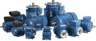
The asynchronous electric motor is powered from a three-phase AC network. Such a motor, with a simple connection diagram, is equipped with three windings located on the stator. Each winding is shifted relative to each other by an angle of 120 degrees. A shift at such an angle is intended to create rotation of the magnetic field.
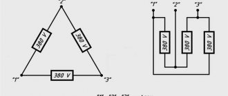
The ends of the phase windings of the electric motor are brought out to a special “block”. This was done for ease of connection. In electrical engineering, two main methods are used for connecting asynchronous electric motors: the “delta” connection method and the “star” method. When connecting the ends, jumpers specially designed for this purpose are used.
Differences between "star" and "triangle"
Based on the theory and practical knowledge of the basics of electrical engineering, the “star” connection method allows the electric motor to operate smoother and softer. But at the same time, this method does not allow the engine to reach the full power presented in the technical specifications.
By connecting the phase windings in a delta pattern, the motor is able to quickly reach maximum operating power. This allows you to use the full efficiency of the electric motor, according to the technical data sheet. But this connection scheme has its own drawback: large inrush currents. To reduce the value of currents, a starting rheostat is used, allowing for a smoother start of the engine.
Connection options
Three-phase motors have excellent characteristics, a fairly wide range of models and are used in a wide variety of devices. Therefore, they are used both in industrial devices with three-phase power supply, and in household single-phase electrical installations. Next, we will analyze both options for connecting electrical machines.
To a single-phase network
The design feature of a three-phase unit, in contrast to single-phase asynchronous motors, is the need for a phase shift in the windings, otherwise the shaft will not rotate. To change the situation, one phase is divided for all three windings, two of which include additional inductance and starting capacitance. Which provide a shift in current and voltage relative to the voltage in the network. Inductance allows you to shift the voltage to the negative region up to -90°, but a single-phase capacitor, on the contrary, to the positive region up to +90°.
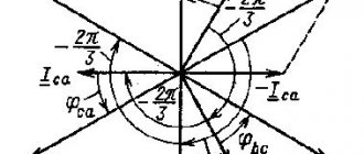
Graphically, the voltage-current lag function will look like this:
Change in current and voltage across capacitance and inductance
However, in practice, the bias is provided only by capacitive elements, which are included in the power supply circuit of one of the windings, and the other two are run between the phase and neutral wires. The connection diagram for a three-phase motor in a single-phase circuit is shown in the figure below:
Connection diagram to a single-phase network
As you can see in the figure, a tap is made from the phase wire containing a single-phase capacitor magazine of two elements, one for starting C2, the second for constant operation of C1. When the start button is pressed, contacts SA1 and SA2 close simultaneously, but after sufficient torque has been created and rotation has begun, SA1 is discarded and removes C1 from the circuit, leaving C2. Power, with this engine switching scheme, is reduced to 30 - 50%.
Capacitor starting is calculated using the formula:
Serb = (2800*I)/U - to turn on a three-phase motor with a star
Crab = (4800*I)/U - to turn on a three-phase motor with a triangle
The starting capacitor is used only in loaded starting, so it can not be used in light starting. Then, instead of the launcher capacity, the worker will be used.
To a three-phase network
In a three-phase network, despite the presence of the required type of supply voltage, a magnetic starter is always used to drive the motor into rotation. Starting without a starter or contactor is quite dangerous, so they are an integral element.
Connection diagram to a three-phase network
The figure above shows a typical diagram for connecting a motor to a three-phase network, which works on the following principle:
- Voltage is supplied to the engine from the mains through switch 1.
- further, when the start button 6 is turned on, the contactor coil 4 is powered, which attracts the power contacts of the starter 3;
- after which the engine begins to rotate, and the start button 6 is bridged through the repeater 5;
- to stop the three-phase motor, use the Stop button - 7, which is in the normally closed position;
- Motor overload protection monitors the current load in the network and, if a threat arises, opens contacts 2.
This diagram can be simplified due to the design features of the starters used. Since some of them are manufactured without repeaters, they may have the function of reversing a three-phase motor or be produced without protection. You can get more detailed information about magnetic starters from the corresponding article on the website:
Star connection and its advantages
Reversible motor circuit 380 to 220 Volts
Each of the three working windings of the electric motor has two terminals - the beginning and the end, respectively. The ends of all three windings are connected to one common point, the so-called neutral.
If there is a neutral wire in the circuit, the circuit is called 4-wire, otherwise, it will be considered 3-wire.
The beginning of the terminals is connected to the corresponding phases of the supply network. The applied voltage on such phases is 380 V, less often 660 V.
The main advantages of using the star scheme:
- Stable and long-term non-stop operation of the engine;
- Increased reliability and durability by reducing equipment power;
- Maximum smooth start-up of the electric drive;
- Possibility of exposure to short-term overload;
- During operation, the equipment housing does not overheat.
There is equipment with internal connection of the ends of the windings. Only three pins will be output to the block of such equipment, which does not allow the use of other connection methods. Electrical equipment made in this form does not require competent specialists for its connection.
Connecting a three-phase motor to a single-phase network using a star circuit
Control circuit
Connection of operational voltage, through time relay contact K1 and contact K2, in the coil circuit of contactor K3. Turning on contactor K3 opens contact K3 in the coil circuit of contactor K2 (blocking erroneous activation), contact K3 closes in the coil circuit of contactor K1 combined with a pneumatic time relay.
Turning on contactor K1 closes contact K1 in the coil circuit of contactor K1 (self-feeding), at the same time the pneumatic time relay is turned on, which opens its contact K1 in the coil circuit of contactor K3 after a certain time, and also closes its contact K1 in the coil circuit of contactor K2. Disabling contactor K3, contact K3 closes in the coil circuit of contactor K2. Turning on contactor K2 opens contact K2 in the coil circuit of contactor K3 (blocking erroneous activation).
Triangle connection and its advantages
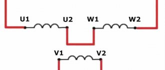
The principle of the “triangle” connection is to connect in series the end of the winding of phase A with the beginning of the winding of phase B. And then, by analogy, the end of one winding with the beginning of another. As a result, the end of the phase C winding closes the electrical circuit, creating an unbroken circuit. This scheme could be called a circle, if not for the mounting structure. The triangle shape is given by the ergonomic placement of the winding connection.
When connected by a “triangle” on each of the windings, there is a linear voltage equal to 220V or 380V.
The main advantages of using the triangle scheme:
- Increasing the power of electrical equipment to the maximum value;
- Using a starting rheostat;
- Increased torque;
- Large traction forces.
Flaws:
- Increased starting current;
- When running for a long time, the engine gets very hot.
The “triangle” method of connecting motor windings is widely used when working with powerful mechanisms and the presence of high starting loads. A large torque is created due to an increase in the self-induction EMF caused by large flowing currents.
Connecting a three-phase motor to a single-phase network using a triangle diagram
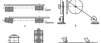
Connecting transformer windings in a zigzag
A zigzag connection is used when there is uneven load on the secondary loads. After the zigzag connection, the load is distributed more evenly across the phases and the magnetic flux of the transformer remains in balance despite the uneven load.
Consider the zigzag star connection of a three-phase power transformer. A schematic representation is shown in the figure.
The primary windings are connected in a star. Next, we divide each secondary winding in half. And then we connect as shown in the figure.
When connecting into a zigzag star, a larger number of turns will be required than with a simple star. Also, with this connection it is possible to obtain three voltage classes, for example 380-220-127V.
Bookmark or share with friends
Source: pomegerim.ru
Star-delta connection type
In complex mechanisms, a combined star-delta circuit is often used. With this switching, power increases sharply, and if the engine, according to its technical characteristics, is not designed to operate using the “delta” method, it will overheat and burn out.
Motors with increased power have high starting currents, and as a result, when starting, they often cause fuses to blow and circuit breakers to turn off. To reduce the line voltage in the stator windings, autotransformers, universal chokes, starting rheostats or a star connection are used.
Star and delta connection diagrams
In this case, the voltage at the connection of each winding will be 1.73 times less, therefore, the current flowing during this period will be less. Then the frequency increases and the current reading continues to decrease. Then, using a relay contact circuit, a switch from “star” to “triangle” will occur.
As a result, using this combination, we will obtain maximum reliability and effective productivity of the electrical equipment used, without fear of damaging it.
Star-delta switching is permissible for electric motors with a light starting mode. This method is not applicable if it is necessary to reduce the starting current and at the same time not reduce the high starting torque. In this case, a wound-rotor motor with a starting rheostat is used.
Main advantages of the combination:
- Increased service life. Smooth start allows you to avoid uneven load on the mechanical part of the installation;
- Possibility of creating two power levels.
INCLUSION OF ENERGY RECEIVERS INTO THE THREE-PHASE CURRENT NETWORK
Electric lamps are manufactured for rated voltages of 127 and 220 V, and three-phase electric motors for rated phase voltages of 127, 220 and 380 V
and higher.
The method of connecting the receiver to a three-phase current network depends on the line voltage of the network and on the rated voltage of the receiver.
Lamps with a nominal voltage of 127 V
switched on by a triangle at a linear network voltage of 127
V
and a star with a neutral wire at a linear network voltage of 220
V.
Lamps with a rated voltage of 220
V
are connected by a triangle into a network with a linear voltage of 220
V
and a star with a neutral wire into a network with a linear voltage of 380
V.
A three-phase electric motor is connected by a delta into a network whose line voltage is equal to the rated phase voltage of the electric motor. If the line voltage of the network exceeds √3 times the rated phase voltage of the electric motor, then it is turned on as a star.
Article on the topic Connecting energy receivers with a triangle
Blitz tips
- At the moment of starting the electric motor , its starting current is 7 times greater than the operating current.
- The power is 1.5 times greater when connecting the windings using the delta method.
- To create a smooth start and protect against motor overloads , frequency wires are often used.
- When using the star connection method , special attention is paid to the absence of “phase imbalance”, otherwise the equipment may fail.
- Linear and phase voltages in a delta connection are equal to each other, as are line and phase currents in a star connection.
- To connect the motor to a household network, a phase-shifting capacitor is often used.
Connecting the electric motor windings in a star configuration
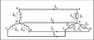
When connecting the phases of an electric motor with a star, the three windings are connected to each other at a common point. The free ends are each connected to their own phase of the network. In some cases, the common point is connected to the neutral bus of the power supply system.
The figure shows that for this connection, the phase voltage of the network is applied to each winding (for 0.4 kV networks - 220 volts).
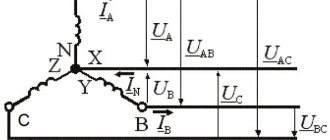
Phase voltage - elements of a three-phase circuit
Three phase generator
Currently, alternating current electrical energy is generated, transmitted and distributed between individual current collectors in a three-phase circuit system.
A three-phase circuit system is a set of electrical circuits in which the current collectors receive power from a common three-phase generator.
Rice. 1. Three-phase generator diagram
A three-phase generator is one that has a winding consisting of three parts. Each part of this winding is called a phase. Therefore, these generators are called three-phase.
It should be noted that the term “phase” in electrical engineering has two meanings:
- in the sense of a certain stage of a periodic oscillatory process;
- as the name of a part of an alternating current electrical circuit (for example, part of the winding of an electrical machine).
To understand the principle of operation of a three-phase generator, let us turn to the model schematically depicted in Figure 64. The model consists of a stator, made in the form of a steel ring, and a rotor - a permanent magnet. There is a three-phase winding on the stator ring with the same number of turns in each phase. The phases of the winding are shifted in space one relative to the other by an angle of 120°.
Let's imagine that the rotor of the generator model is rotated at a constant speed counterclockwise. Then, due to the continuous movement of the poles of the permanent magnet relative to the conductors of the stator winding, an EMF will be induced in each phase
By applying the right-hand rule, one can be convinced that the EMF induced in the winding phase by the north pole of a rotating magnet will act in one direction, and that induced by the south pole in the other. Consequently, the EMF of the generator phase will be variable.
The extreme points (clamps) of each phase of the generator are always marked: one extreme point of the phase is called the beginning, and the other - the end. The beginnings of the phases are designated by Latin letters A
,
B
,
C
X
,
Y
,
Z,
respectively . The names “beginning” and “end” of a phase are given based on the following rule: the positive EMF of the generator acts in the direction from the end of the phase to its beginning.
Let us agree to consider the emf of the generator positive if it is induced by the north pole of a rotating magnet. Then the marking of the generator terminals for the case of counterclockwise rotation of its rotor should be as shown in Figure 1.
At a constant speed of rotation of the rotor poles, the amplitude and frequency of the EMF created in the phases of the stator winding remain unchanged. However, at every instant, the magnitude and direction of action of the EMF of one of the phases differ from the magnitude and direction of action of the EMF of the other two phases. This is explained by the spatial phase shift. All phenomena in the second phase repeat the phenomena in the first phase, but with a delay. They say that the emf of the second phase lags in time from the emf of the first phase. For example, they reach their amplitude values at different times. Indeed, the greatest value of the EMF induced in any phase will be at the moment when the center of the rotor pole passes the middle of this phase. In particular, for the moment of time corresponding to the rotor location shown in Figure 1, the electromotive force of the first phase of the generator will be positive and maximum. The positive maximum value of the second phase EMF will occur later, when the rotor rotates through an angle of 120°. Since during one revolution of a two-pole generator rotor a complete cycle of EMF change occurs, the time T of one revolution is the period of EMF change. Obviously, to rotate the rotor by 120°, a time equal to one third of the period (T/3) is required.
Consequently, all stages of change in the EMF of the second phase occur later than the corresponding stages of change in the EMF of the first phase by one third of the period. The same lag in the periodic change in EMF is observed in the third phase in relation to the second. It goes without saying that in relation to the first phase, periodic changes in the EMF of the third phase occur with a delay of two-thirds of the period ( 2/3 T
).
By giving the appropriate shape to the poles of the magnets, it is possible to achieve a change in the EMF over time according to a law close to sinusoidal.
Rice. 2. Curves of instantaneous values of a three-phase EMF system
Therefore, if the change in EMF of the first phase of the generator occurs according to the sine law
e1 = Emsinωt
,
then the law of change in the EMF of the second phase can be written by the formula
e2 = Em sinω (t − T/3)
,
and the third - by the formula
e3 = Em sinω (t − 2/3 T)
,
This is illustrated by the graph in Figure 2.
Thus, we can draw the following conclusion: with uniform rotation of the rotor poles, variable EMFs of the same frequency and amplitude are induced in all three phases of the generator, periodic changes of which in relation to each other occur with a delay of 1/3 of the period.
Three-phase current collectors
A three-phase generator serves as a power source for both single-phase and three-phase electrical devices. Single-phase current collectors, as is known, have two external terminals. These include, for example, lighting lamps, various household appliances, electric welding machines, induction furnaces, electric motors with single-phase windings.
Three-phase devices generally have six external terminals. Each such device consists of three, usually identical, electrical circuits, which are called phases. Examples of three-phase current collectors include electric arc furnaces with three electrodes or electric motors with three-phase windings.