CHARACTERISTICS COLLECTOR CONTROL
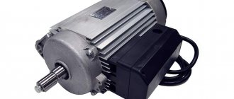
AC motors (ACM) belong to the category of power units, the basis of which is the principle of converting electrical energy into mechanical rotation.
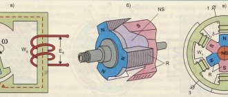
The operation of such electrical devices is based on the effect of a rotating magnetic field created in the stator due to the appropriate distribution of the supply voltage. To understand the operating principle of AC motors, you will need to familiarize yourself with the existing varieties of these units.
Types of AC motors.
Depending on the design features and the nature of the connection between the electromagnetic (e/m) field of the rotating rotor and the EMF of the stationary stator, synchronous and asynchronous motors are distinguished. In the first, this connection is rigid, but in asynchronous, their rotation frequencies differ by the amount of the so-called “slip”.
Based on the number of poles, electromagnetic stator coils and type of supply voltage, all known models are divided into:
- single-phase (including capacitor);
- three-phase AC motors;
- stepper (multiphase) units.
Based on the method of organizing excitation and the nature of the connection with the rotor, commutator and brushless electric motors are distinguished.
TECHNICAL CHARACTERISTICS OF ELECTRIC MOTORS
Regardless of the type of electrical machine (synchronous or asynchronous, commutator or brushless), they all have the following technical characteristics:
- number of working phases – one or three (except for stepper models);
- electrical and shaft power;
- winding connection diagrams (“star” or “delta”);
- equipment protection class.
In single-phase machines, starting is carried out either manually, or they are equipped with a special starting winding (phase-shifting chain with a capacitor).
In 3-phase units, a rotating electric field is created by three independent coils placed on the stator at an angle of 120 degrees to one another. The corresponding emfs are spaced in electrical space at the same angles.
Types of power:
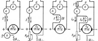
1. Electrical power is the power consumed from the network by the phase windings of the motor in operating mode.
2. Mechanical power on the shaft - the rotational force developed by the EPT, measured in Watts and characterizing the conversion efficiency or efficiency of the entire engine.
Winding connection diagram
is selected taking into account the design features of the unit and its operating conditions. Most often, household electrical equipment and tools use a star-type connection circuit.
Motor protection class
from the penetration of mechanical particles of dirt, as well as from the ingress of moisture, is installed in accordance with the EN 60034 standard.
To designate it, use two English letters IP followed by numbers. The first corresponds to the level of protection against the ingress of solid particles, and the second - from the penetration of moisture into the interior.
Read an abstract on electrical engineering: “Electric motors” Page 1
(Back)
The “read” function is used to familiarize yourself with the work. The markup, tables and pictures of the document may be displayed incorrectly or not in full!
Introduction.
Electrical machines are widely used in power plants, in industry, in transport, in aviation, in automatic control and control systems, and in everyday life.
Electrical machines convert mechanical energy into electrical energy and vice versa. A machine that converts mechanical energy into electrical energy is called a generator. The conversion of electrical energy into mechanical energy is carried out by motors.
Any electric machine can be used both as a generator and as an electric motor. This property of an electric machine to change the direction of the energy it converts is called the reversibility of the machine. An electrical machine can also be used to convert electrical energy of one type of current (frequency, number of AC phases, DC voltage) into energy of another type of current. Such electrical machines are called converters.
Depending on the type of current in the electrical installation in which the electrical machine must operate, they are divided into direct and alternating current machines.
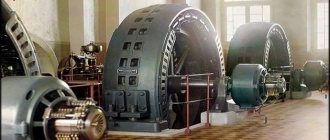
AC machines can be either single-phase or multi-phase. The most widely used are three-phase synchronous and asynchronous machines, as well as alternating current catheter machines, which allow economical regulation of the rotation speed over a wide range
Currently, asynchronous motors are the most common electrical machines. They consume about 50% of the electricity generated by the country's power plants. Asynchronous electric motors have become so widespread because of their design simplicity, low cost, and high operational reliability. They have a relatively high efficiency: at powers above 1 kW efficiency = 0.7:0.95 and only in micromotors it decreases to 0.2-0.65.
Along with great advantages, asynchronous motors also have some disadvantages: consumption from the network of reactive current necessary to create a magnetic flux, as a result of which asynchronous motors operate with cos = 1. In addition, they are inferior to DC motors in terms of their ability to regulate the rotation speed.
The appearance of three-phase asynchronous motors is associated with the name of M.O. Dolivo-Dobrovolsky. These engines were invented by him in 1889.
Operating principle of asynchronous motors
The most common among electric motors was the three-phase asynchronous motor, first designed by the famous Russian electrician M.O. Dolivo-Dobrovolsky.
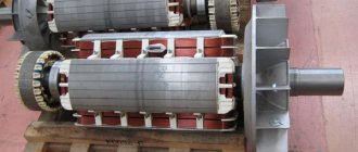
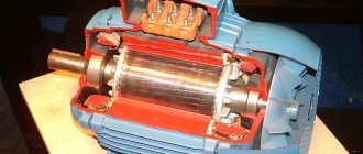
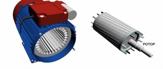
The asynchronous motor is characterized by its simple design and ease of maintenance. Like any AC machine, an induction motor consists of two main parts - the rotor and the stator. The stator is the stationary part of the machine, the rotor is its rotating part. An asynchronous machine has the property of reversibility, that is, it can be used both in generator mode and in motor mode. Due to a number of significant disadvantages, asynchronous generators are practically not used, while asynchronous motors have become very widespread.
Multi-phase winding
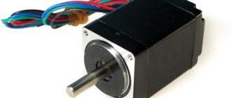
COLLECTOR AC MOTOR
The design of commutator electric motors contains the following mandatory components:
- rotor of a special design;
- stator with main and exciting windings;
- collector unit with a set of brushes.
The basis of the rotor (armature) is a magnetic circuit made of electrical steel plates, between the poles of which, during manufacture, turns of copper wire are laid according to a certain pattern.
The ends of the windings are brought out to the collector unit, which is the switching part of the system (here they are switched). With its help, the armature winding is connected to the stator winding in a series chain. At the same time, the field created in it interacts with the magnetic flux of the stator, creating the necessary torque.
Advantages and disadvantages.
The advantages of commutator AC motors include smooth starting and simplicity of the exciting circuit circuit connected in series with the main winding. The possibility of obtaining significant torques is also noted. These products are reliable in operation and “hold” the maximum loads on the shaft well.
A distinctive feature is a wide range of operating powers (from hundreds of watts to tens of kW).
The disadvantages of these units are presented below:
- increased noise level;
- low efficiency compared to brushless designs;
- the need for constant maintenance of the collector unit due to wear and contamination of its elements (lamellas);
- the need to update and adjust the brushes;
- high level of radio interference.
The disadvantages of commutator electric motors also include the insufficient reliability of working units and the short service life of their constituent elements.
Areas of use.
The scope of application of commutator motors is determined by the peculiarities of their design.
At a mains voltage frequency of 50 Hz, the shaft rotation speed of these products reaches 9000-10000 rpm. That is why motors with a commutator unit are widely used in household equipment of various classes.
This:
- washing machines;
- electric meat grinders, coffee grinders and mixers;
- power tools (drills, grinders, hammer drills, etc.).
Today, traditional brushed motors are being replaced wherever possible by modern brushless units.
With the expansion and reduction in cost of the modern electronic base, their production becomes more profitable. At the same time, control circuits operating on semiconductor elements of various classes are being improved.
Induction
Previously, we established how an ordinary magnet rotates in a stator. AC motors have rotors rather than magnets. Our model is very similar to a real rotor, except that the rotor is polarized under the influence of a magnetic field. This is caused by magnetic induction, due to which an electric current is induced in the rotor conductors.
Induction
Basically the rotor works the same way as a magnet. When the electric motor is turned on, current flows through the stator winding and creates an electromagnetic field that rotates in a direction perpendicular to the rotor windings. Thus, a current is induced in the rotor windings, which then creates an electromagnetic field around the rotor and rotor polarization.
In the previous section, to make it easier to explain the principle of operation of the rotor, replacing it with a magnet for clarity. Now let's replace the stator with a magnet. Induction is a phenomenon that occurs when a conductor moves in a magnetic field. The relative movement of a conductor in a magnetic field leads to the appearance of a so-called induced electric current in the conductor. This induced current creates a magnetic field around each rotor conductor winding. Since three-phase AC power causes the stator's magnetic field to rotate, the induced magnetic field of the rotor will follow this rotation. This way the motor shaft will rotate. AC motors are often called AC induction motors, or AC induction motors.
Features of diagnostics of synchronous motors
To check the electric motor, it is necessary to completely de-energize the tool and disassemble it. If there is a short circuit, the insulating material inside will begin to melt and an unpleasant odor will appear. Therefore, the first thing you need to do is smell the rotor. If there are no signs of breakdown, then check the condition of the lamellas on the anchor. This is done using a multimeter.
Switch it to resistance measurement mode with a threshold of 200 Ohms. Ring all adjacent slats. If the resistance changes, this indicates that there is a breakdown inside the coil. Instead of a multimeter, you can use a simple incandescent lamp. To do this, you need to connect the electric motor to a 12 Volt power source and install an incandescent lamp in the gap. Rotating the shaft by hand, you need to look at the behavior of the lamp.
If the lamp begins to blink, this indicates the presence of an interturn short circuit. If it does not light up at all, then there is a break in the power circuit, or one of the lamellas is faulty. To carry out repairs, it is necessary to replace the winding and install new insulation. Only in this case the engine will not burn out. Be sure to test the AC motor after repair. To increase the service life of the motor, it is necessary to rewind the rotor every two years.
220 volt connection
Unlike a three-phase motor, a two-phase motor is initially designed to be connected to a single-phase network. To obtain a phase shift between the windings, a working capacitor is switched on, which is why two-phase motors are also called capacitor motors.
The capacity of the working capacitor is calculated using formulas for the nominal operating mode. But when the mode differs from the nominal one, for example, during startup, the balance of the windings is disrupted . To ensure the starting mode during start and acceleration, an additional starting capacitor is connected in parallel to the working one, which must be turned off when reaching the rated speed.
Typical faults
The brush-commutator mechanism requires the greatest attention, in which sparking is observed even when the new engine is running. Worn out brushes should be replaced to prevent more serious problems: overheating of the commutator lamellas, their deformation and peeling. In addition, an interturn short circuit of the armature or stator windings may occur, which results in a significant drop in the magnetic field or strong sparking of the commutator-brush junction.
Premature failure of a universal commutator motor can be avoided by proper operation of the device and the professionalism of the manufacturer during the assembly process of the product.