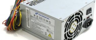
The power supply is the PC hardware component that supplies power to the internal devices. It receives it from the home electrical network and converts alternating current into direct current, which is needed by the computer elements. And it also regulates the voltage within the computer network to an operating level, which allows the machine to operate stably and not overheat. It is an integral part of any PC and must work properly for other components to function reliably. Therefore, if the power supply does not start, the user needs to check it and, if necessary, repair or replace it.
All about power supplies
AC mains current cannot be directly supplied to the PC because its components use DC power and must first undergo a rectification process. This transition determines the main task of the power supply unit (PSU) as an AC rectifier.
The source is designed in such a way that it guarantees standard voltage to all PC components. To do this, it distributes the power across different cables with operating voltages. For example, a DVD hard drive connector provides 5 volts for the electronics and 12 volts for its drive motor.
PC components have different connections, but each source has all the necessary connectors for a standard assembly. Particularly important: the unit must have enough plugs for hard drives and CD/DVD drives that additional drives can be easily installed.
Most office PCs have a small 300W model. A PC adapter that supports gaming should provide at least 400W of power because strong processors and fast graphics cards require a lot of power. In this case, a failure may occur where the power supply starts and turns off immediately.
If your PC runs multiple video cards, you may need a 500 or 650 W model. Currently, devices with a power of 1,000 watts are sold. But they are rarely applicable. If you purchase a low-power unit, the computer may fail, for example, while playing games or watching videos. This happens because the corresponding PC components consume a lot of energy. Overheating is the main reason why a power supply won't start.
Checking a repaired power supply
After the ATX unit has been repaired, it is important to properly turn it on for the first time. At the same time, if not all problems have been resolved, the repaired and new components of the device may fail.
The power supply can be started autonomously, without using a computer unit. To do this, the PS_ON contact is bridged with the common wire. Before switching on, a 60 W light bulb is soldered in place of the fuse, and the fuse is removed. If the light bulb starts to shine brightly when turned on, then there is a short circuit in the unit. If the lamp flashes and goes out, the lamp can be unsoldered and a fuse installed.
The next stage of checking the power supply occurs under load. First, the presence of standby voltage is checked; for this, the output is loaded with a load of about two amperes. If the duty station is in order, the power supply is turned on by closing PS_ON, after which measurements of the output signal levels are made. If you have an oscilloscope, you can see the ripple.
Description of ATX DC Power Supply
The ATX unit is a power converter. It converts the alternating current (AC) supplied by the power supply company into direct current (DC) with the required voltage level sufficient for the PC components, which corresponds to 110-115 or 220-230 volts.
This conversion is performed using the processes:
- switching;
- straightening;
- filtration.
Many PCs have a unit called SMPS or pulse. When the switching power supply fails to start and needs to be tested, users must strictly follow the safety precautions and precautions to protect against electric shock. The power supply contains dangerous voltages and currents. There are capacitors inside that store energy and can cause electric shock, so repairs to the unit should only be performed by qualified personnel.
Recommendations and protective measures in cases where the ATX power supply does not start:
- The user can easily find the source on the system unit by seeing the input to which the cord is connected, without opening the computer.
- If you unplug and remove the PSU, it will look like a metal box with a fan inside and several cables attached to it.
- The average user is not recommended to disconnect the power supply; it is better to leave it in the case.
We are looking for the culprit
As we see in the diagram, standby power, hereinafter referred to as standby power, is designated as +5VSB:
Directly from it goes a zener diode with a nominal value of 6.3 Volts to the ground. And as you remember, a zener diode is the same diode, but connected in reverse in circuits. The zener diode uses the reverse branch of the current-voltage characteristic. If the zener diode were live, then our +5VSB wire would not short to ground. Most likely the zener diode has burned out and the PN junction is destroyed.
What happens when various radio components burn from a physical point of view? Firstly, their resistance changes. For resistors, it becomes infinite, or in other words, goes into a break. With capacitors it sometimes becomes very small, or in other words, goes into a short circuit. With semiconductors, both of these options are possible, both a short circuit and an open circuit.
In our case, we can check this in only one way, by unsoldering one or both legs of the zener diode, as the most likely culprit of the short circuit. Next, we will check whether the short circuit between the duty switch and ground has disappeared or not. Why is this happening?
Let's remember some simple tips:
1) When connected in series, the rule of greater than greater works, in other words, the total resistance of the circuit is greater than the resistance of the larger resistor.
2) With a parallel connection, the opposite rule works, less than the smaller, in other words, the final resistance will be less than the resistance of the resistor of the smaller value.
You can take arbitrary resistor resistance values, calculate them yourself and see for yourself. Let's try to think logically, if one of the resistances of parallel-connected radio components is zero, what readings will we see on the multimeter screen? That's right, also equal to zero...
And until we eliminate this short circuit by desoldering one of the legs of the part that we consider to be problematic, we will not be able to determine in which part we have a short circuit. The point is that during audio testing, ALL parts connected in parallel to the part that is in a short circuit will ring short with the common wire!
We try to remove the zener diode. As soon as I touched it, it fell apart in two. No comments…
PSU: computer hardware component
PS, P/S or PSU are abbreviations for power supply unit. Below is a list of items that come with the power supply:
- Power cord to computer.
- Housing to prevent dust from entering the power supply.
- Fan for cooling and air removal.
- Switch for changing voltage.
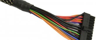
- Cable packages located on the front internal panel of the power supply unit. They connect to the computer's motherboard and internal components. Therefore, if the power supply does not start, the motherboard is the first device that will stop working.
- Drive connectors.
- The motherboard connector is a 24-pin ATX connector which, when connected, provides power to the motherboard.
- Input voltage selector.
The ATX function block provides +5V, 720mA standby current through the purple wire to the motor pin. This current is also supplied to the PCI slots even when the computer is turned off and damaged. Therefore, when the power supply does not start, there is a duty officer. Therefore, it is recommended that when turning off the power supply, wait 30 seconds before starting work inside the system unit in order to take proper precautions against electrostatic discharge.
ATX computer power supply repair
Attention! To avoid damaging the computer, uncoupling and connecting the connectors of the power supply and other components inside the system unit must be performed only after completely disconnecting the computer from the power supply.
(remove the plug from the socket or turn off the switch in the “Pilot”).
The first thing that needs to be done is to check the presence of voltage in the outlet and the serviceability of the “Pilot” type extension cord by the glow of its switch key. Next, you need to check that the computer’s power cord is securely inserted into the “Pilot” and the system unit and that the switch (if any) on the back wall of the system unit is turned on.
How to find a power supply fault by pressing the “Start” button
If power is supplied to the computer, then in the next step you need to look at the power supply cooler (visible behind the grille on the back wall of the system unit) and press the “Start” button of the computer. If the cooler blades move even a little, it means that the filter, fuse, diode bridge and capacitors on the left side of the block diagram are working, as well as the independent low-power power supply +5 B_SB.
In some PSU models, the cooler is on the flat side and to see it, you need to remove the left side wall of the system unit.
Turning at a small angle and stopping the cooler impeller when you press the “Start” button indicates that output voltages momentarily appear at the output of the power supply unit, after which the protection is triggered, stopping the operation of the power supply unit. The protection is configured in such a way that if the current value for one of the output voltages exceeds a specified threshold, then all voltages are turned off.
The cause of an overload is usually a short circuit in the low-voltage circuits of the power supply itself or in one of the computer units. A short circuit usually occurs when there is a breakdown in semiconductor devices or insulation in capacitors.
To determine the node in which a short circuit has occurred, you need to disconnect all power supply connectors from the computer units, leaving only those connected to the motherboard. Then connect the computer to the power supply and press the “Start” button. If the cooler in the power supply was spinning, it means that one of the disconnected nodes is faulty. To determine the faulty node, you need to connect them in series to the power supply.
If the power supply connected only to the motherboard does not work, you should continue troubleshooting and determine which of these devices is faulty.
Checking the computer power supply by measuring the resistance value of the output circuits
When repairing a power supply, some types of its malfunction can be determined by measuring with an ohmmeter the resistance value between the common black GND wire and the remaining contacts of the output connectors.
Before starting measurements, the power supply must be disconnected from the power supply, and all its connectors must be disconnected from the system unit components. The multimeter or tester must be turned on in resistance measurement mode and select a limit of 200 Ohms. Connect the common wire of the device to the connector contact to which the black wire goes. The end of the second probe touches the contacts in turn, in accordance with the table.
| Table of resistance between the terminals of the ATX power supply | ||||||
| Output voltage, V | +3,3 | +5,0 | +12,0 | -12,0 | +5.0 SB | GND |
| Wire color | orange | red | yellow | blue | violet | black |
| Resistance should be more than ohm | 6,5 | 20 | 130 | 98 | 46 | — |
| Most probable values, Ohm | 7, 15, 32, ∞ | 50, 96, 200, ∞ | 136, 264, ∞ | 98,195, ∞ | 46, 98, ∞ | — |
The table shows generalized data obtained as a result of measuring the resistance value of the output circuits of 20 serviceable power supply units of computers of different capacities, manufacturers and years of manufacture.
To be able to connect a power supply for testing without load, load resistors are installed inside the unit at some outputs, the value of which depends on the power of the power supply and the manufacturer’s decision. Therefore, the measured resistance can fluctuate over a wide range, but should not be below the permissible value.
If a load resistor is not installed in the circuit, then the ohmmeter readings will vary from a small value to infinity. This is due to the charging of the filter electrolytic capacitor from the ohmmeter and indicates that the capacitor is working. If you swap the probes, a similar picture will be observed. If the resistance is high and does not change, then the capacitor may be broken.
A resistance less than the permissible value indicates the presence of a short circuit, which may be caused by an insulation breakdown in an electrolytic capacitor or a rectifying diode. To determine the faulty part, you will have to open the power supply and unsolder one end of the filter choke of this circuit from the circuit. Next, check the resistance before and after the throttle. If after it, then there is a short circuit in the capacitor, wires, between the tracks of the printed circuit board, and if before it, then the rectifier diode is broken.
Troubleshooting the power supply by external inspection
Initially, you should carefully inspect all the parts, paying special attention to the integrity of the geometry of the electrolytic capacitors. As a rule, due to severe temperature conditions, electrolytic capacitors fail most often. About 50% of power supply failures are due to faulty capacitors. Often, swelling of capacitors is a consequence of poor performance of the cooler. The cooler bearings run out of lubrication and the speed drops. The cooling efficiency of the power supply parts decreases and they overheat. Therefore, at the first sign of a malfunction of the power supply cooler, additional acoustic noise usually appears; you need to clean the cooler from dust and lubricate it.
If the capacitor body is swollen or traces of leaked electrolyte are visible, then the failure of the capacitor is obvious and it should be replaced with a serviceable one. The capacitor swells in the event of an insulation breakdown. But it happens that there are no external signs of failure, but the level of output voltage ripple is greater. In such cases, the capacitor is faulty due to lack of contact between its terminal and the plate inside it, as they say, the capacitor is broken. You can check the capacitor for open circuit using any tester in resistance measurement mode. The technology for testing capacitors is presented in the website article “Measuring Resistance”.
Next, the remaining elements, fuse, resistors and semiconductor devices are inspected. Inside the fuse, a thin metal wire should run along the center, sometimes with a thickening in the middle. If the wire is not visible, then most likely it has burned out. To accurately check the fuse, you need to test it with an ohmmeter. If the fuse is blown, it must be replaced with a new one or repaired. Before making a replacement, to check the power supply, you can not solder the blown fuse from the board, but solder a copper wire with a diameter of 0.18 mm to its terminals. If the wiring does not burn out when you turn on the power supply to the network, then it makes sense to replace the fuse with a working one.
How to check the serviceability of the power supply by closing the PG and GND contacts
If the motherboard can only be checked by connecting it to a known-good power supply, then the power supply can be checked separately using a load block or started by connecting the +5 V PG and GND contacts to each other.
From the power supply to the motherboard, supply voltages are supplied using a 20 or 24 pin connector and a 4 or 6 pin connector. For reliability, the connectors have latches. In order to remove the connectors from the motherboard, you need to press the latch upward with your finger at the same time, applying quite a lot of force, rocking from side to side, and pull out the mating part.
Next, you need to short-circuit the two terminals in the connector removed from the motherboard with each other, using a piece of wire or perhaps a metal paper clip. The wires are located on the latch side. In the photographs, the location of the jumper is indicated in yellow.
If the connector has 20 pins
, then you need to connect pin
14
(green wire, in some power supplies it may be gray, POWER ON) and pin
15
(black wire, GND).
If the connector has 24 pins
, then you need to connect pin
16
(green, in some power supplies the wire may be gray, POWER ON) and pin
17
(black GND wire).
If the impeller in the power supply cooler rotates, then the ATX power supply can be considered operational, and, therefore, the reason for the computer not working is in other units. But such a check does not guarantee stable operation of the computer as a whole, since deviations in output voltages may be greater than permissible.
Checking the computer's power supply by measuring voltages and ripple levels
After repairing the power supply or in case of unstable operation of the computer, in order to be completely sure that the power supply is in good working order, it is necessary to connect it to the load block and measure the level of output voltages and the ripple range. The deviation of voltage values and ripple amplitude at the output of the power supply should not exceed the values given in the table.
You can do without a load block by measuring the voltage and ripple level directly at the terminals of the power supply connectors in a running computer.
| Table of output voltages and ripple range of ATX power supply | |||||||
| Output voltage, V | +3,3 | +5,0 | +12,0 | -12,0 | +5.0 SB | +5.0 PG | GND |
| Wire color | orange | red | yellow | blue | violet | grey | black |
| Permissible deviation, % | ±5 | ±5 | ±5 | ±10 | ±5 | – | – |
| Permissible minimum voltage | +3,14 | +4,75 | +11,40 | -10,80 | +4,75 | +3,00 | – |
| Permissible maximum voltage | +3,46 | +5,25 | +12,60 | -13,20 | +5,25 | +6,00 | – |
| Ripple range no more than, mV | 50 | 50 | 120 | 120 | 120 | 120 | – |
When measuring voltages with a multimeter, the “negative” end of the probe is connected to the black wire (common), and the “positive” end to the desired connector contacts.
Voltage +5 V SB (Stand-by), purple wire – produces an independent low-power power supply built into the power supply unit, made on one field-effect transistor and transformer. This voltage ensures the computer operates in standby mode and serves only to start the power supply. When the computer is running, the presence or absence of +5 V SB voltage does not matter. Thanks to +5 V SB, the computer can be started by pressing the “Start” button on the system unit or remotely, for example, from an uninterruptible power supply unit in the event of a prolonged absence of 220 V supply voltage.
Voltage +5 V PG (Power Good) - appears on the gray wire of the power supply unit after 0.1-0.5 seconds if it is in good condition after self-testing and serves as an enabling signal for the operation of the motherboard.
A voltage of minus 12 V (blue wire) is only needed to power the RS-232 interface, which is absent in modern computers. Therefore, power supplies of the latest models may not have this voltage.
How to replace a fuse in a computer's power supply
Typically, computer power supplies are equipped with a tubular glass fuse designed for a protection current of 6.3 A. For reliability and compactness, the fuse is soldered directly into the printed circuit board. For this purpose, special fuses are used that have terminals for sealing. The fuse is usually installed in a horizontal position next to the surge protector and is easy to spot by its appearance.
But sometimes there are power supplies in which the fuse is installed in a vertical position and a heat-shrinkable tube is put on it, as in the photo above. As a result, it is difficult to detect. But the inscription on the printed circuit board next to the fuse helps: F1 - this is how the fuse is designated on electrical circuits. Next to the fuse, the current for which it is rated may also be indicated; on the presented board, a current of 6.3 A is indicated.
When repairing the power supply and checking the vertically installed fuse using a multimeter, it was discovered that it was broken. After desoldering the fuse and removing the heat shrink tubing, it became obvious that it had blown. The inside of the glass tube was completely covered with a black coating from the burnt wire.
Fuses with wire leads are rare, but they can be successfully replaced with ordinary 6.3 ampere fuses by soldering single-core pieces of copper wire with a diameter of 0.5-0.7 mm to the ends of the cups.
All that remains is to solder the prepared fuse into the printed circuit board of the power supply and check its functionality.
If, when the power supply is turned on, the fuse burns out again, it means that there is a failure of other radio elements, usually a breakdown of the transitions in the key transistors. Repairing a power supply with such a fault requires high qualifications and is not economically feasible. Replacing a fuse designed for a higher protection current than 6.3 A will not lead to a positive result. The fuse will still blow.
Searching for faulty electrolytic capacitors in the power supply
Very often, a power supply failure, and as a result, unstable operation of the computer as a whole, occurs due to swelling of the electrolytic capacitor housings. To protect against explosion, notches are made at the end of electrolytic capacitors. As the pressure inside the capacitor increases, the housing swells or ruptures at the notch, and by this sign it is easy to find a failed capacitor. The main reason for the failure of capacitors is their overheating due to a malfunction of the cooler or exceeding the permissible voltage.
The photo shows that the capacitor on the left side has a flat end, while the end on the right is swollen, with traces of leaking electrolyte. This capacitor has failed and must be replaced. In the power supply, electrolytic capacitors on the +5 V power bus usually fail, since they are installed with a small voltage margin, only 6.3 V. I have encountered cases when all the capacitors in the power supply on the +5 V circuit were swollen.
When replacing capacitors on a 5 V power supply circuit, I recommend installing capacitors that are designed for a voltage of at least 10 V. The higher the voltage the capacitor is designed for, the better, the main thing is that the dimensions fit into the installation location. If a capacitor with a higher voltage does not fit due to its size, you can install a capacitor with a smaller capacity, but designed for a higher voltage. All the same, the capacity of the capacitors installed at the factory has a large reserve and such a replacement will not worsen the performance of the power supply and the computer as a whole.
The larger the capacity of the installed capacitor, the better. So when replacing, it is better to choose a capacitor designed for a higher voltage and capacity than that of the failed one. Replacing a failed capacitor in a power supply is not difficult if you have the skills to work with a soldering iron. The article on the website “How to solder with a soldering iron” is devoted to soldering techniques.
There is no point in replacing electrolytic capacitors in the power supply if they are all swollen. This means that the output voltage stabilization circuit has failed, and a voltage exceeding the permissible value was applied to the capacitors. Such a power supply can be repaired only with professional education and measuring instruments, but such repairs are not economically feasible.
The main thing when repairing a power supply is not to forget that electrolytic capacitors have polarity. On the negative terminal side of the capacitor body there is a marking in the form of a wide light vertical stripe, as shown in the photo above. On the printed circuit board, the hole for the negative terminal of the capacitor is located in the marking area of the white (black) semicircle, or the hole for the positive terminal is indicated by a “+” sign.
Checking the group stabilization choke BP ATX
If you suddenly smell something burning from the computer system unit, then one of the reasons may be overheating of the group stabilization choke in the power supply unit or a burnt winding of one of the coolers. The computer usually continues to work normally. If, after opening the system unit and inspecting it, all coolers rotate, then the throttle is faulty. The computer must be turned off immediately and repaired.
The photo shows a computer power supply with the cover removed, in the center of which you can see the inductor, covered with green insulation, burnt on top. When I connected this power supply to the load and applied supply voltage to it, after a couple of minutes a thin stream of smoke came out of the inductor. The check showed that all output voltages within the tolerance and the ripple range do not exceed the permissible value.
The current of all voltages supplying the computer passes through the inductor and it is obvious that there has been a violation of the insulation of the wires of the windings as a result of which they short-circuited among themselves.
The windings can be rewinded onto the same core, but as a result of strong heating, the magnetodielectric of the core may lose its quality factor; as a result, due to high Foucault currents, it will heat up even with intact windings. Therefore, I recommend installing a new throttle. If there is no analogue, then you need to count the turns of the windings, winding them on the burnt inductor, and wind them with an insulated wire of the same cross-section on a new core. In this case, the direction of the windings must be observed.
Checking other power supply elements
Resistors and simple capacitors should not have any darkening or deposits. The cases of semiconductor devices must be intact, without chips or cracks. When making repairs yourself, it is advisable to replace only the elements shown in the block diagram. If the paint on the resistor has darkened, or the transistor has fallen apart, then there is no point in changing them, since most likely this is a consequence of the failure of other elements that cannot be detected without instruments. A darkened resistor body does not always indicate a malfunction. It is quite possible that only the paint has darkened, but the resistance of the resistor is normal.
Diagnosis of nutrition problems
Power problems can be difficult to diagnose, especially if the user doesn't know what to look for. Here are some tips on how to quickly identify the problem if the power supply does not start and how to resolve this failure.
A bad source can be the cause of many PC problems. Experience can help a technician diagnose problems caused by a faulty source that is usually ignored by new technicians.
Any intermittent problem may be caused by a faulty source. Common symptoms when a computer power supply does not start:
- Failure when turning on voltage.
- Spontaneous reboot or intermittent blocking during stable operation.
- Memory errors.
- HDD and fan do not rotate.
- Overheating due to the fan being turned off.
- Frequent shutdowns that cause system restarts.
- Electric shocks that are felt when touching the body.
There are also some obvious clues that should answer the question of why the power supply won't start. These include:
- A system that is completely dead, nothing happens in it when the PC is turned on.
- Smoke that appears when you turn on your PC.
Another way to check the power supply is to use special software. It can detect changes in temperature or performance, and will show how much power is being supplied to which components, which will help solve the problem faster.
Checking the input resistance
So, they gave us a 350-watt Power Man power supply for repair.
What do we do first? External and internal inspection. Let's look at the "offal". Are there any burnt radio elements? Maybe the board is charred somewhere, or a capacitor has exploded, or it smells like burnt silicon? We take all this into account during the inspection. Be sure to look at the fuse. If it burns out, then replace it with a temporary jumper for about the same amount of Amperes, and then measure the input resistance through two network wires. This can be done on the power supply plug with the “ON” button turned on. It should NOT be too small, otherwise, when you turn on the power supply, a short circuit will occur again.
Electrical test of power supply
First, make sure that the computer is connected to the mains through an outlet. If necessary, you can use a lamp or hair dryer to make sure the electrical outlet is working. In some cases, there is a switch on the power supply, make sure it is on. Sometimes the unit may have a smaller red switch installed to select the voltage type.
Latest power supplies sometimes have an electrical filter that prevents the computer from rebooting after a short circuit. To fix this glitch, simply unplug the power cord from the computer, then press and hold the power button for a few seconds to discharge the accumulated energy and reset the protection.
The power supply works correctly if the voltage in the wires corresponds to the following parameters:
- blue + 11.20 V;
- yellow + 11.20 V;
- purple + 5.20 V;
- orange + 3.33 V;
- red + 5.20 V;
- white + 5.20 V;
- gray + 5.20 V.
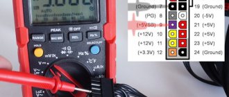
Power supplies are not designed to operate in standby mode, so voltages may vary slightly from the table below and for this reason the supply should only be operated in this manner for a short time. Voltage by contact numbers:
- No. 1 - 3.3 V;
- No. 2 - 12 V;
- No. 3, 5, 6, 7 - GND;
- No. 4 - food;
- No. 8 - 5 V;
- No. 9, 10 - 5 V;
- No. 11, 12 - 3.3 V;
- No. 13, 15, 17 - GND;
- No. 14, 16 - 5 V;
- No. 18 - PW-OK;
- No. 19 - 5 V;
- No. 20 - 12 V.
For current power supplies, the Power/On control line is usually green.
Necessary tools for repair
In order to begin repairing the power supply yourself, you should have the necessary tools on hand.
First you need to arm yourself with computer diagnostic tools:
- working power supply unit;
- post card;
- The memory stick is in working condition;
- compatible video card;
- CPU;
- multimeter;
To perform the repair itself you will also need:
- soldering iron and everything for soldering;
- screwdrivers;
- the computer is in working order;
- oscilloscope;
- tweezers;
- insulating tape;
- pliers;
- knife;
Naturally, this is not so much for a complete renovation, but this is enough for home renovation.
Simplified ATX Test Method
If the ATX power supply does not start, check that it is operating correctly and that its voltages comply with the manufacturer's specifications. To perform these tests, use a screwdriver to open the box and a cable to bypass the power. In this case, use a simple paperclip and one multimeter to perform the necessary measurements. First of all, you need to take certain precautions before opening the PSU case. The source must be unplugged and the power button on the rear panel must be in the off position.
First you need to open the box with a screwdriver and find the power supply connector, consisting of 24 (20 + 4) contacts. Once found, disconnect it from the motherboard. The next step is to find a green wire called PS_ON (PowerSupply ON), which is connected to the common black cable of the PSU. Using a jumper with a clamp, the green wire is connected to any black wire of the connector, after which the source will be artificially turned on without the need to connect the base board. After this, connect the power cable to the mains and press the button on the rear panel to turn it on. In order to make sure that the bridge is made correctly, turn on the power source, and if the fan rotates and drives air, then everything is done correctly.
Now you need to take measurements, for which you use a multimeter. Red and black connectors are located in the tension measurement position: black connector for COM and red for V Hz.
The rotary switch is located in the DC voltage measurement area at position 20 as it will measure voltages of 3.3V, 5V and 12V.
Where is the power supply located in the system unit and how to disassemble it
To gain access to the computer's power supply, you must first remove the left side wall from the system unit by unscrewing two screws on the rear wall on the side where the connectors are located.
To remove the power supply from the system unit case, you need to unscrew the four screws marked in the photo. To conduct an external inspection of the power supply, it is enough to disconnect from the computer units only those wires that interfere with the installation of the power supply on the edge of the system unit case.
Having placed the power supply on the corner of the system unit, you need to unscrew the four screws located on top, in the pink photo. Often one or two screws are hidden under a sticker, and to find the screw you need to peel it off or pierce it with the tip of a screwdriver. There are also stickers on the sides that make it difficult to remove the cover; they need to be cut along the line of mating parts of the power supply housing.
After the cover from the power supply unit is removed, be sure to remove all dust with a vacuum cleaner. It is one of the main reasons for the failure of radio components, since by covering them with a thick layer, it reduces the heat transfer from the parts, they overheat and, working in difficult conditions, fail faster.
For reliable operation of the computer, it is necessary to remove dust from the system unit and power supply, and also check the operation of coolers at least once a year.
A quick note about polarity
If the power supply does not start the first time, when checking, you need to ensure the polarity of the measurements with a multimeter. Place the black multimeter measuring wire in any common cable, and the red one in turn in a cable of different colors, which are located in the power supply connector. Voltages are measured to ensure compliance with the certified values specified by the manufacturer. All voltages that will be determined are constant. The power supply wires are color coded.
The test leads are also color coded: red is positive (+) and black is negative (-). To check the output voltage on the motherboard, place the black test lead on the black pin and the red test lead on the Power_Good pin (P8-1) of the AT, Baby AT and LPX power supplies, and pin 3 on the 20-pin ATX connectors. It should read +3 to +6 volts DC. If the user does not see this voltage, then the unit is faulty.
Any voltage within 10 percent of the specified voltage is acceptable for testing purposes. Some problems cannot be detected by direct measurement, so having replacement inventory is essential.
Principles of measuring radioelements
The power supply housing is connected to the common wire of the printed circuit board. The power part of the power supply is measured relative to the common wire . The limit on the multimeter is set to more than 300 volts. In the secondary part there is only a constant voltage not exceeding 25 volts.
Checking resistors is carried out by comparing the readings of the tester and the markings applied to the resistance body or indicated on the diagram. The diodes are checked with a tester; if it shows zero resistance in both directions, then a conclusion is made that it is faulty. If it is possible to check the voltage drop across the diode in the device, then you don’t have to solder it, the value is 0.5-0.7 volts.
Capacitors are checked by measuring their capacitance and internal resistance, which requires a specialized ESR meter. When replacing, be aware that capacitors with low internal resistance (ESR) are used. Transistors are checked for the operability of pn junctions or, in the case of field ones, for the ability to open and close.
Revision using the advanced tester
The following instructions only apply to the dedicated ATX Coolmax PS-228 power supply tester, or any other similar tester with an LCD screen.
Important: This process is considered complex, the user needs to carefully follow the instructions below.
Time required: Testing a PSU with a PSU test device usually takes about 30 minutes, or a little more for beginners.
Algorithm of actions:
- Learn important safety tips when repairing your PC. Testing a power supply involves working with high voltage electricity, a potentially hazardous activity. Safety should be the main concern during a block inspection.
- Open the case by first turning off the computer, disconnecting the power cord and everything connected to the outside of the computer.
- Move the disconnected unit to a place where you can easily work, such as a desk. The user will not need a keyboard, mouse, monitor or other external peripheral devices.
- Disconnect the power connectors of each internal unit on the side panel. An easy way to ensure that each power connector is unplugged is to remove the power cord kit that comes from the PSU. Each group of cables must end with one or more power connectors. There is no need to disconnect data cables or other cables that are not connected to the power supply.
- Group all power cables and connectors for easy testing. When organizing power cables, it is recommended to disconnect them and remove them from the computer case as far as possible. This will make connecting the power connectors to the extended tester as easy as possible.
- Make sure the power supply voltage switch located on the rear panel is correctly set for your country of residence. In the US this switch should be set to 110V/115V, and in Russia to 220/230.
- Connect the 24-pin ATX power connector and the 4-pin ATX power connector on the motherboard in the PC power supply tester. Depending on the source, there may not be a 4-pin motherboard connector, but there may be 6 or 8 pins. If there is more than one type, simply connect one at a time along with the 24-pin main power connector.
- Connect the power supply to an electrical outlet and turn on the switch. Some units do not have a switch on the rear panel. If the source being tested does not work, simply connect the device to supply power. Press and hold the on/off button of the tester for PC power supplies. The user should hear the fan inside the source start to operate.
Some versions of the improved Coolmax PS-228 power supply tester do not require constantly pressing the power button. Just because the fan is running doesn't mean the power supply is properly supplying power to the rest of your devices. If the power supply fan does not start during testing, even if the source is in good condition, it may be burnt out and should be checked separately.
The Advanced Source Tester's LCD display should be turned on and the user will see test numbers for all metrics. If the voltage shows "LL" or "HH" or if the LCD does not light up, the PSU is not working and will need to be replaced.
Block diagram of the power supply unit of an ATX computer
A computer power supply is a rather complex electronic device and repairing it requires deep knowledge of radio engineering and the availability of expensive equipment, but, nevertheless, 80% of failures can be eliminated independently, having the skills of soldering, working with a screwdriver and knowing the block diagram of the power source.
Almost all computer power supplies are made according to the block diagram below. I have shown the electronic components in the diagram only those that most often fail and are available for non-professionals to replace on their own. When repairing an ATX power supply, you will definitely need color coding of the wires coming out of it.
The supply voltage is supplied via a power cord through a plug-in connection to the power supply board. The first element of protection is fuse Pr1, usually rated at 5 A. But depending on the power of the source, it may have a different rating. Capacitors C1-C4 and inductor L1 form a filter that serves to suppress common-mode and differential noise that arises from the operation of the power supply itself and can come from the network.
Surge filters assembled according to this scheme are required to be installed in all products in which the power supply is made without a power transformer, in televisions, VCRs, printers, scanners, etc. Maximum efficiency of the filter is possible only when connected to a network with a ground wire. Unfortunately, cheap Chinese computer power supplies often do not have filter elements.
Here is an example of this: the capacitors are not installed, and instead of the inductor, jumpers are soldered. If you are repairing a power supply and find that filter elements are missing, it is advisable to install them.
Here is a photo of a high-quality computer power supply, as you can see, filter capacitors and a noise suppression choke are installed on the board.
To protect the power supply circuit from supply voltage surges, expensive models install varistors (Z1-Z3), pictured on the right side in blue. Their operating principle is simple. At normal network voltage, the resistance of the varistor is very high and does not affect the operation of the circuit. If the voltage in the network increases above the permissible level, the resistance of the varistor sharply decreases, which leads to the fuse blowing, and not to the failure of expensive electronics.
To repair a failed unit due to overvoltage, it will be enough to simply replace the varistor and fuse. If you don’t have a varistor at hand, then you can only get by by replacing the fuse; the computer will work normally. But at the first opportunity, in order not to take risks, you need to install a varistor in the board.
Some models of power supplies provide the ability to switch to operate at a supply voltage of 115 V; in this case, the contacts of switch SW1 must be closed.
For a smooth charge of electrolytic capacitors C5-C6, connected immediately after the rectifier bridge VD1-VD4, an RT thermistor with a negative TCR is sometimes installed. In a cold state, the resistance of the thermistor is a few ohms; when current passes through it, the thermistor heats up and its resistance decreases by 20-50 times.
To be able to turn on the computer remotely, the power supply has an independent, additional low-power power source that is always on, even if the computer is turned off, but the electrical plug is not removed from the socket. It generates a voltage of +5 B_SB and is built according to the circuit of a transformer self-oscillating blocking oscillator on a single transistor, powered from a rectified voltage by diodes VD1-VD4. This is one of the most unreliable components of the power supply and is difficult to repair.
The voltages required for the operation of the motherboard and other devices of the system unit, when leaving the voltage generation unit, are filtered from interference by chokes and electrolytic capacitors and then supplied to consumption sources through wires with connectors. The cooler, which cools the power supply itself, is powered, in older power supply models from a voltage of minus 12 V, in modern ones from a voltage of +12 V.
Monitoring peripheral power connectors
If you need to check individual connectors, continue testing the power supply. Verification algorithm:
- Turn off the switch on the power supply panel and unplug it from the outlet.
- Connect the tester socket connector to the corresponding SATA connector with a 15-pin Molex modification. Do not connect more than one of these peripheral connectors at the same time, otherwise the tester may be damaged.
- Two connectors on the motherboard must remain connected for these tests with other connectors.
- Connect the source, and then turn on the button on the panel.
- The LEDs labeled +12V, +3.3V, and +5V correspond to the voltage supplied through the connected peripheral power connector and should be lit as expected. Otherwise, the power supply needs to be replaced.
- The SATA connector provides +3.3 VDC. You can see the voltage supplied by different connectors by looking at the ATX connector output pin charts.
- Repeat this process for the other power connectors one at a time, except for the connector on the motherboard, which remain connected to the tester at all times.
- After completing the tests, turn off the power supply, disconnect the tester cables, and then connect the internal devices of the PC to the source.
- After the power supply has been tested or replaced with a new one, you can turn on the PC again.
Low-voltage power elements
These elements are installed on a separate radiator.
Let us remind you that the power supply has at least two separate radiators - one for high-voltage elements, the other for low-voltage elements.
If the block has an active PFC circuit, then it will have its own heatsink, i.e. there will be three in total.
The power elements of the low-voltage part are, as a rule, dual Schottky rectifier diodes. These diodes differ from conventional ones in that less voltage drops across them.
Thus, at the same current, they dissipate less power and heat less.
The diode assembly has a common cathode, which is why it has three rather than four terminals. How to check diodes is written here.
How to determine the health of varistors and thermistors?
On power supply diagrams, varistors and thermistors have similar symbols in the form of a resistor with a body crossed out with a “stick”. Varistors are usually placed parallel to the current source and are marked with the designation VR:
Thermistors are designated similarly:
Thermistors are usually connected in series with the load; their resistance is much less than varistors.
Checking the serviceability of a varistor/thermistor consists of two steps:
Test run
After replacing faulty parts, it is necessary to test turn on the unit.
In this case, instead of a fuse, you should turn on an electric lamp 220 - 230 V with a power of 40 - 100 W. The fact is that the malfunction of the high-voltage power transistors could be caused by a malfunction of the control microcircuit-controller. In this case, the controller may mistakenly open both transistors at once.
The so-called through (very large) current will flow through them, and they will fail . After replacing the transistors - even if the controller is faulty - almost all the voltage will drop across the lamp. The current will be limited and the transistors will remain intact.
So, if after replacing the transistors the lamp lights up at full intensity, the controller or the so-called “piping” (additional parts) around it is faulty. But this is already a complex malfunction . To eliminate it, you need to know how the controller works and what signals it produces.
Therefore, we will leave this case to the professionals. If the lamp blinks for a short time and goes out (or burns with a barely noticeable glow), then there is no through current through the transistors.
It should be noted that the circuitry of power supplies is constantly being improved, so this method of test switching on, generally speaking, cannot always be recommended.
If you use it, please remember that you use it at your own risk.
If the test run went well, you can measure
PSU load
It is necessary to warn that switching on switching power supplies without load significantly reduces their service life and can even cause failure. Therefore, we recommend assembling a simple load block; its diagram is shown in the figure.
Load block diagram
It is advisable to assemble the circuit using resistors of the PEV-10 brand, their ratings are: R1 - 10 Ohms, R2 and R3 - 3.3 Ohms, R4 and R5 - 1.2 Ohms. Cooling for the resistances can be made from aluminum channel.
It is not advisable to connect a motherboard or, as some “craftsmen” advise, a HDD and CD drive as a load during diagnostics, since a faulty power supply can damage them.
Pinout of the main PSU connector
To carry out repairs, we will also need to know the pinout of the main power connector, it is shown below.
PSU plugs: A – old style (20pin), B – new (24pin)
To start the power supply, you need to connect the green wire (PS_ON#) to any black zero wire. This can be done using a regular jumper. Note that some devices may have color markings that differ from the standard ones; as a rule, unknown manufacturers from the Middle Kingdom are guilty of this.